
- •Главная
- •1.1 Напряжений и концентраторы
- •1.1.3 Концентраторы напряжения
- •1.3 Stress concentration factor
- •1.7 Elastic-plastic stress concentration
- •1.8 Joints: bolts and welds
- •3. Механические свойства конструкционных материалов
- •3.1 Напряженности испытания
- •3.2 Stress - strain diagram
- •3.3 Testing schemes
- •3.4 Strength
- •4 Прочность материалов
- •4.1 Tension and compression
- •4.2 Shear and torsion
- •4.3 Stress-strain state
- •4.4 Bending: force and moment diagrams
- •4.5 Geometrical characteristics of sections
- •4.6 Bending: stress and deformation
- •4.7 Mixed mode loading
- •4.8 Buckling
- •4.9 Statically indeterminate systems
- •4.10 Three-dimensional structures
- •References
- •5. Theory of elasticity
- •5.1 Deformation
- •5.2 Stress
- •5.3 Hooke's law
- •5.4 Plane problems
- •5.5 Torsion
- •5.6 Bending
- •5.7 Polar coordinates
- •5.8 Plates
- •5.9 Shells
- •5.10 Contact stresses
- •6.2 Distribution functions
- •6.3 Structural models of reliability
- •6.4 Limiting state
- •6.5 Dispersion
- •6.6 Durabilty
- •6.7 Design by reliability criterion
- •6.8 Risk
- •6.9 Safety classes
- •6.10 Risk : structural and social
- •References
- •7 Materials science
- •7.1 Crystalline solids
- •7.2 Mechanical properties
- •7.3 Failure
- •7.4 Phase diagrams
- •7.5 Heat treatment of metals and alloys
- •7.6 Corrosion of metals and alloys
- •7.7 Casting
- •7.8 Polymers
- •7.9 Composites
- •7.10 Forming of metals
- •8.2 Mechanical properties
- •8.3 Stress concentration
- •8.4 Defects
- •8.5 Residual Stress
- •8.6 Strength
- •8.7 Fatigue strength
- •8.8 Fracture
- •8.9 Weldability
- •References
- •9 Composites
- •9.1 Structure of composites
- •9.2 Fibers
- •9.3 Rigidity
- •9.4 Strength
- •9.5 Crack resistance
- •9.6 Optimization
- •9.7 Fatigue and temperature effect
- •9.8 Reliability
- •9.9 Joints
- •9.10 Material selection
- •References
- •10 Finite element analysis
- •10.1 Finite element method
- •10.2 Finite elements
- •10.3 Meshing
- •10.4 Boundary conditions
- •10.5 Deformation
- •10.6 Accuracy
- •10.7 Heat transfer analysis
- •10.8 Dynamics
- •10.9 Computational fluid dynamics
- •10.10 Design analysis
- •References
4.3 Stress-strain state
 Normal
stress in simple tension is given by s=Force/Area. If we cut the
section at an angle j, there are two stress components perpendicular
(sn)
and parallel (t) to the incline plane.
The maximum shear
stress occuring at j=45o
is equal to half of maximum axial stress s.
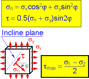 For
a bi-axial state of stress, normal stress sn
and shear stress t on an inclined plane depend on the two shown
stress components.
 For
common plane stress state there are two perpendicular planes
(principle planes) where there is no shear stress and normal stresses
are a minimum and maximum. The two components are known as the
principle stresses.
 Maximum
shear stress acts at the planes inclined 45o
to principle planes.
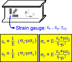 Hooke's
law generally includes two constants of the material: Young's modulus
E and Poisson's ratio m.
 In
the general case, maximum shear stress depends on two principle
stresses only - maximum and minimum.
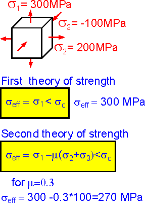 According
to the first theory of strength fracture occurs if the maximum
principle stress exceeds its critical value.
According to
the second theory of strength fracture occurs if the maximum tensile
strain exceeds its critical value. This can be transformed into an
equation with the equivalent stress depending on all three stress
components and Poisson's ratio.
According
to the first theory of strength fracture occurs if the maximum
principle stress exceeds its critical value.
According to
the second theory of strength fracture occurs if the maximum tensile
strain exceeds its critical value. This can be transformed into an
equation with the equivalent stress depending on all three stress
components and Poisson's ratio.
4.4 Bending: force and moment diagrams
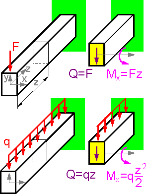 A
cantilever beam is fully constrained on one end, attached to a wall
for example, and has a load acting at the other end.
Static equilibrium conditions
Static equilibrium conditions are applied to determine the external support reactions, and the external moment acting on the beam in the embedded end:
Sum of forces including internal transverse (shear) force Q in Y-direction is equal to zero.
Sum of the moments relative to the chosen point, including internal bending moment Mx, is equal to zero.
The
resulting internal bending moment in the beam is proportional to the
distance from the free end z. The situation is similar if load is
distributed q.
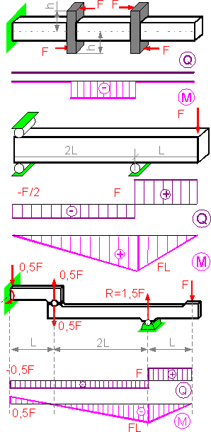
 The
figures show different loading schemes and corresponding diagrams of
shear force Q and bending moment M. For the same external load, the
support structure can affect the maximum values of the bending moment
M.


4.5 Geometrical characteristics of sections
 Bending
tensile and shear stresses depend on the section geometry, not only
the cross-sectional area A. The section can be characterized by the
following:
moments of inertia Ixx, Iyy,
polar moment of inertia J.
The
last characteristic is important for analysis of torsion deformation.
The moments of inertia have units of [length4]. Polar moment of
inertia is equal to sum of the other two moments. It does not depend
on orientation of the axes.
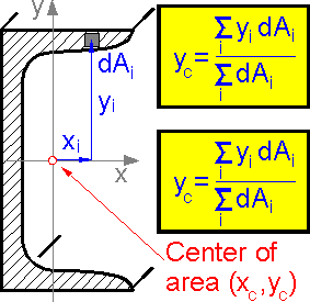 The
moments of inertia depend on the placement and orientation of the
axes. Practical engineers use values of the moments of inertia which
pass through the center of the area called the centroid
(xc,yc).
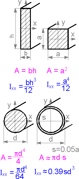 For
simple geometry the moment of inertia can be easy calculated. For
more complicated sections, the information can be found in reference
books.
 The
moment of inertia Ixx
is higher if many elements of the area are located far from the
neutral axis. The removed area of the circle decreases the moment of
inertia. The decrease is small if the distance from the neutral axis
to the center of the hole is small.
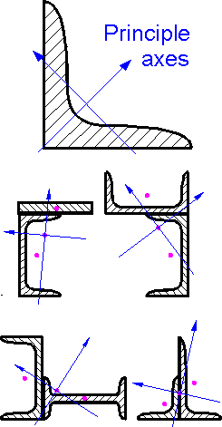 For
a symmetrical geometry the principle axes pass through the centroid
(center of area). An axis coincides with the line of symmetry.
For
a composite cross-section an axis tends towards the region with most
area furthest from the neutral axis.
For
a symmetrical geometry the principle axes pass through the centroid
(center of area). An axis coincides with the line of symmetry.
For
a composite cross-section an axis tends towards the region with most
area furthest from the neutral axis.
