- •Главная
- •1.1 Напряжений и концентраторы
- •1.1.3 Концентраторы напряжения
- •1.3 Stress concentration factor
- •1.7 Elastic-plastic stress concentration
- •1.8 Joints: bolts and welds
- •3. Механические свойства конструкционных материалов
- •3.1 Напряженности испытания
- •3.2 Stress - strain diagram
- •3.3 Testing schemes
- •3.4 Strength
- •4 Прочность материалов
- •4.1 Tension and compression
- •4.2 Shear and torsion
- •4.3 Stress-strain state
- •4.4 Bending: force and moment diagrams
- •4.5 Geometrical characteristics of sections
- •4.6 Bending: stress and deformation
- •4.7 Mixed mode loading
- •4.8 Buckling
- •4.9 Statically indeterminate systems
- •4.10 Three-dimensional structures
- •References
- •5. Theory of elasticity
- •5.1 Deformation
- •5.2 Stress
- •5.3 Hooke's law
- •5.4 Plane problems
- •5.5 Torsion
- •5.6 Bending
- •5.7 Polar coordinates
- •5.8 Plates
- •5.9 Shells
- •5.10 Contact stresses
- •6.2 Distribution functions
- •6.3 Structural models of reliability
- •6.4 Limiting state
- •6.5 Dispersion
- •6.6 Durabilty
- •6.7 Design by reliability criterion
- •6.8 Risk
- •6.9 Safety classes
- •6.10 Risk : structural and social
- •References
- •7 Materials science
- •7.1 Crystalline solids
- •7.2 Mechanical properties
- •7.3 Failure
- •7.4 Phase diagrams
- •7.5 Heat treatment of metals and alloys
- •7.6 Corrosion of metals and alloys
- •7.7 Casting
- •7.8 Polymers
- •7.9 Composites
- •7.10 Forming of metals
- •8.2 Mechanical properties
- •8.3 Stress concentration
- •8.4 Defects
- •8.5 Residual Stress
- •8.6 Strength
- •8.7 Fatigue strength
- •8.8 Fracture
- •8.9 Weldability
- •References
- •9 Composites
- •9.1 Structure of composites
- •9.2 Fibers
- •9.3 Rigidity
- •9.4 Strength
- •9.5 Crack resistance
- •9.6 Optimization
- •9.7 Fatigue and temperature effect
- •9.8 Reliability
- •9.9 Joints
- •9.10 Material selection
- •References
- •10 Finite element analysis
- •10.1 Finite element method
- •10.2 Finite elements
- •10.3 Meshing
- •10.4 Boundary conditions
- •10.5 Deformation
- •10.6 Accuracy
- •10.7 Heat transfer analysis
- •10.8 Dynamics
- •10.9 Computational fluid dynamics
- •10.10 Design analysis
- •References
10.9 Computational fluid dynamics
Computational
fluid dynamics (CFD) provides insight into transient and turbulent
flow. The mechanical principles governing fluids and solids are the
same. CFD uses numerical methods such as the finite element method,
the finite difference method, the boundary element method, and the
finite volume method. It allows analysis and optimization of
structural component geometry for efficient fluid flow. It also
allows one to view pressure, velocity, and temperature in the flow.
 Dynamics
is the study of motion of objects.
A fluid actually means
anything that isn't a solid. Both air and water are fluids from this
point of view. Fluids are considered as any "shapeless"
substance which cannot remain at rest under a sliding stress.
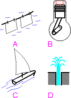
The
following are examples of the problem that can be solved by CFD:
A.
Hanging wet clothes out to dry.
B. Burning gasoline in an
automobile engine.
C. Sailing.
D. A jet of water issuing
from a slit.
E. Dissolution.
F. Melting, boiling .
G.
Mechanical movement of a fan.
H. Gas flow in jet engine.
 n
the CFD-based analysis the Navier-Stokes equations take the form of a
large system of nonlinear equations. There are three fundamental
principles of computational fluid dynamics:
Energy is
conserved.
Mass is conserved.
Momentum is
conserved.
 Temperature,
the pressure, the three velocity components, and density are typical
variables for fluid flow. The flow variables can be stored at the
center of the computational cell (Cell Centered methods) or at the
vertices of the cell (Cell Vertex or Vertex Centered methods). The
acoustic-fluid model is the simplest: the fluid only transmits
pressure waves, fluid-particle motions are small. Only one degree of
freedom (the potential) needs to be calculated at each finite-element
node in potential-based analysis.
 CFD
simulates steady and unsteady flow in air and in boundary layers. The
mesh is created to represent the air configuration surrounding a
solid. The mesh is more dense for the boundary layers.
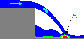
Zones
with turbulence flow demand a fine local grid resolution. Zone A for
water falling from a step is an example of such a region
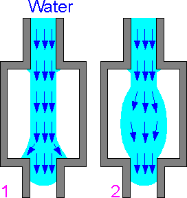
 There
are two different quantitive results for a jet of water issued at a
constant low velocity (<5 cm/s) from a long slit into air
chamber:
1. The distortion in the inlet hole can be
observed in the exact model and the experiment.
2. The
enlargement of the flow in the center may be caused by numerical
errors in the boundary layer between water and air.
 This
is a rough estimation of the turbulence depending on Reynolds Number
Re. Re is meant to measure the relative importance of fluid inertia
to viscous forces. Outside the boundary layer, the flow is
independent of the Reynolds Number. Viscous forces are negligible if
the Reynolds number is large.
n is the kinematic viscosity
of the fluid;
L and U are characteristic length and velocity
scales for a flow.
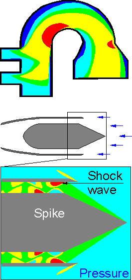
 The
result of CFD modeling is color contours of pressure, velocity, and
temperature. Contrary to solid bodies where stress concentration
usually takes place at notches or holes, the concentration of CFD
parameters can be observed on a smooth surface.
Supersonic
flow in a jet engine with a spike: the primary shock wave originates
at nose of the spike and impinges on the inner surface of the intake
nozzle. This is a the region of pressure concentration.
The
relative difficulty or ease of the CFD-based analysis depend on
dimensionality in time (varying or not varying with time),
dimensionality in space (one- , two-, or three-dimensional space),
complexity of the geometry of the solids, and complexity of the
flow-influencing boundary conditions. If available computer resources
are not sufficient for the necessary numerical accuracy, and
assumptions were made for the input data the result of CFD-based
modeling may not be reliable . The reliability is greater for laminar
rather than turbulent flows, and for chemically-inert rather than
chemically-reactive gases.
The
result of CFD modeling is color contours of pressure, velocity, and
temperature. Contrary to solid bodies where stress concentration
usually takes place at notches or holes, the concentration of CFD
parameters can be observed on a smooth surface.
Supersonic
flow in a jet engine with a spike: the primary shock wave originates
at nose of the spike and impinges on the inner surface of the intake
nozzle. This is a the region of pressure concentration.
The
relative difficulty or ease of the CFD-based analysis depend on
dimensionality in time (varying or not varying with time),
dimensionality in space (one- , two-, or three-dimensional space),
complexity of the geometry of the solids, and complexity of the
flow-influencing boundary conditions. If available computer resources
are not sufficient for the necessary numerical accuracy, and
assumptions were made for the input data the result of CFD-based
modeling may not be reliable . The reliability is greater for laminar
rather than turbulent flows, and for chemically-inert rather than
chemically-reactive gases.
