- •Главная
- •1.1 Напряжений и концентраторы
- •1.1.3 Концентраторы напряжения
- •1.3 Stress concentration factor
- •1.7 Elastic-plastic stress concentration
- •1.8 Joints: bolts and welds
- •3. Механические свойства конструкционных материалов
- •3.1 Напряженности испытания
- •3.2 Stress - strain diagram
- •3.3 Testing schemes
- •3.4 Strength
- •4 Прочность материалов
- •4.1 Tension and compression
- •4.2 Shear and torsion
- •4.3 Stress-strain state
- •4.4 Bending: force and moment diagrams
- •4.5 Geometrical characteristics of sections
- •4.6 Bending: stress and deformation
- •4.7 Mixed mode loading
- •4.8 Buckling
- •4.9 Statically indeterminate systems
- •4.10 Three-dimensional structures
- •References
- •5. Theory of elasticity
- •5.1 Deformation
- •5.2 Stress
- •5.3 Hooke's law
- •5.4 Plane problems
- •5.5 Torsion
- •5.6 Bending
- •5.7 Polar coordinates
- •5.8 Plates
- •5.9 Shells
- •5.10 Contact stresses
- •6.2 Distribution functions
- •6.3 Structural models of reliability
- •6.4 Limiting state
- •6.5 Dispersion
- •6.6 Durabilty
- •6.7 Design by reliability criterion
- •6.8 Risk
- •6.9 Safety classes
- •6.10 Risk : structural and social
- •References
- •7 Materials science
- •7.1 Crystalline solids
- •7.2 Mechanical properties
- •7.3 Failure
- •7.4 Phase diagrams
- •7.5 Heat treatment of metals and alloys
- •7.6 Corrosion of metals and alloys
- •7.7 Casting
- •7.8 Polymers
- •7.9 Composites
- •7.10 Forming of metals
- •8.2 Mechanical properties
- •8.3 Stress concentration
- •8.4 Defects
- •8.5 Residual Stress
- •8.6 Strength
- •8.7 Fatigue strength
- •8.8 Fracture
- •8.9 Weldability
- •References
- •9 Composites
- •9.1 Structure of composites
- •9.2 Fibers
- •9.3 Rigidity
- •9.4 Strength
- •9.5 Crack resistance
- •9.6 Optimization
- •9.7 Fatigue and temperature effect
- •9.8 Reliability
- •9.9 Joints
- •9.10 Material selection
- •References
- •10 Finite element analysis
- •10.1 Finite element method
- •10.2 Finite elements
- •10.3 Meshing
- •10.4 Boundary conditions
- •10.5 Deformation
- •10.6 Accuracy
- •10.7 Heat transfer analysis
- •10.8 Dynamics
- •10.9 Computational fluid dynamics
- •10.10 Design analysis
- •References
10.6 Accuracy
Numerical
modeling requires approximations and simplifications. The results of
FEA are not error-free. Using such a powerful tool as a "black
box" without proper understanding of the its principal features
can lead users into serious mistakes. Unfortunately human error is
inevitable.
An design engineer must understand:
-
Which FE analysis is appropriate for an engineering problem;
-
What part of the structure must be studied in detail;
missing
value
Formulation errors take place if the finite elements
do not precisely describe the behavior of the physical problem.
Selecting the proper element type and mesh size will reduce
formulation errors. Formulation of boundary conditions is critical
for the analysis. The success of FEA depends on the how closely the
boundary conditions, geometry, and material behavior of the model
match the actual situation.
FEM's approximation of a real
engineering structure with a finite number of finite elements, as
well as the size and shape of the elements can cause discretization
error.
Numerical errors are usually rare in comparison
with the discretization and formulation errors.
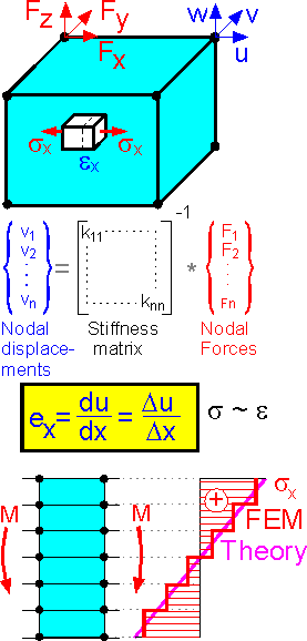
 Displacements
are the primary unknowns. The FEM solution is usually obtained as a
vector of nodal displacement {v}. The solution at other locations
throughout the element is generally calculated by interpolation.
After approximating the displacement field with shape functions the
strain and stress can be calculated. This means that accuracy is at a
maximum for nodal displacements.
Strain is calculated by
determining the difference in displacement between corresponding
points. This is why the accuracy for strain and stress is at a
maximum in the central part of the finite elements.
The
figure shows a stress pattern for bending. The theoretical and
numerical solutions coincide at the center point of the
elements.
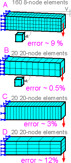
 The
type and number of finite elements affect the accuracy of the
modeling.
For the nonlinear analysis where force is
calculated the number of elements in the model affects the value of
the force for small numbers only. The force becomes more stable with
an increase in the number of elements.
 The
are two methods to increase the accuracy for the solution shown:
H-method increases the number of elements, h is the
length of one side of an element.
P-method increase the
polynomial order of the element.
Second-order elements, B
demonstrate the higher accuracy. For bending of the cantilever beam
one element over the height of the beam is not the best choice. The
more parabolic elements in the length, the better.
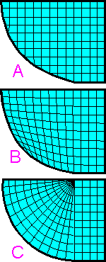
 Mesh
A is preferred for the problem of computational fluid dynamics (CFD).
A. Structured rectangular mesh. Numerical approximations
are centered about the centroid of the rectangle element.
B.
Structured deformed mesh. There are many elements where numerical
approximations are not centered (or symmetrical).
C.
Block-structured mesh. Elements are condensed at one point along the
straight border.
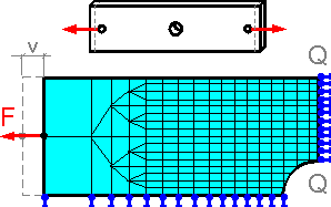
 Nonlinear
structural analysis predicts the behavior of the mild steel specimen.
The coarse mesh at the left end does not have a significant effect on
results for the region with the finer mesh such as the value of
maximum stress, the strain pattern in the net section Q-Q, or
deformed shape of the central hole. The condition of force applied on
the left side of the model roughly agrees with the real situation.
The errors in the numerical diagram "Force - Displacement F-v"
are possible due to the coarse mesh at the left end of the
model.
 Errors
due to numerical analysis increases if small values of volumetric
strain eV
is multiplied by large values of the bulk modulus K. Such analysis
requires additional tests. The situation occurs when Poisson's ratio
approaches a value of 0.5.
