

8.7 Fatigue strength
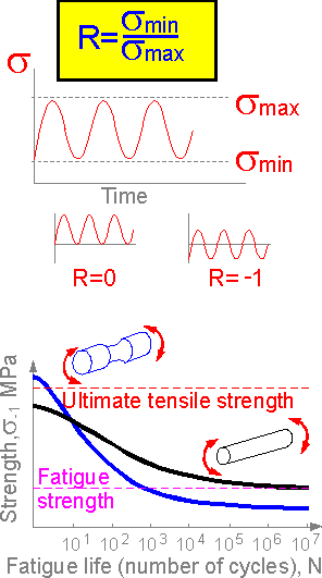 Fatigue
strength is the strength of material under cyclic loading. It has
unit of stress, [MPa]. Fatigue strength is usually two or more times
less than ultimate tensile strength. Fatigue is characterized by
fatigue strength sR,
[MPa] and fatigue life N, [cycles]. R is cycle parameter, equal to
the ratio of minimum and maximum stress.
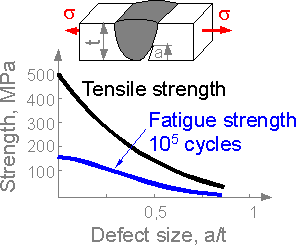
During the
initial cycles a notched ductile steel specimen can sustain stress
exceeding the ultimate tensile stress. Fatigue strength at N=105
of notched specimen is usually lower than the unnotched.
Fatigue
strength is the strength of material under cyclic loading. It has
unit of stress, [MPa]. Fatigue strength is usually two or more times
less than ultimate tensile strength. Fatigue is characterized by
fatigue strength sR,
[MPa] and fatigue life N, [cycles]. R is cycle parameter, equal to
the ratio of minimum and maximum stress.
During the
initial cycles a notched ductile steel specimen can sustain stress
exceeding the ultimate tensile stress. Fatigue strength at N=105
of notched specimen is usually lower than the unnotched.
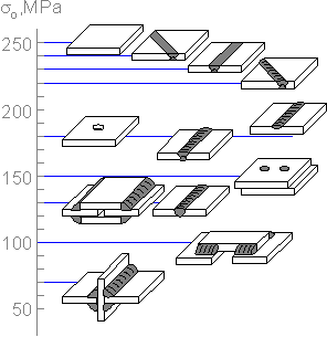 The
figure shows approximate values of fatigue strength for carbon steel
welded joints. The fatigue strength varies over a wide
range.
The
figure shows approximate values of fatigue strength for carbon steel
welded joints. The fatigue strength varies over a wide
range.
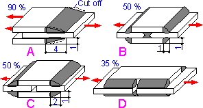 Geometry
of weld affects the fatigue strength. A machined weld demonstrates
greater fatigue strength. The numbers shows percentage of fatigue
strength of a uniform plate under tension.
Geometry
of weld affects the fatigue strength. A machined weld demonstrates
greater fatigue strength. The numbers shows percentage of fatigue
strength of a uniform plate under tension.
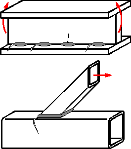
 Fatigue
cracks can start from all defects, but only one crack becomes
dominate and results in failure. Lack of fusion on the surface is a
case where the fatigue crack grows fastest.
Fatigue
cracks can start from all defects, but only one crack becomes
dominate and results in failure. Lack of fusion on the surface is a
case where the fatigue crack grows fastest.
 Initial
manufacturing defects in welds decrease fatigue strength. The
critical stress is sufficiently smaller than the static one.
Initial
manufacturing defects in welds decrease fatigue strength. The
critical stress is sufficiently smaller than the static one.
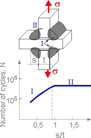 There
are two main mechanisms of fatigue crack growth: I for small weld
sizes s and II for large s. For large values of s the parameter does
not affect the fatigue life of the joint.
There
are two main mechanisms of fatigue crack growth: I for small weld
sizes s and II for large s. For large values of s the parameter does
not affect the fatigue life of the joint.
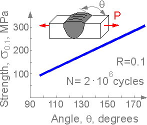 A
large angle q corresponds to high fatigue strength. The effect of
stress increase is higher for fatigue strength than for tensile
strength.
A
large angle q corresponds to high fatigue strength. The effect of
stress increase is higher for fatigue strength than for tensile
strength.
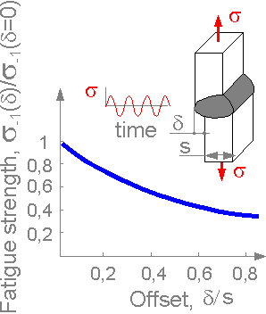 Imperfections
such as offset d decreases fatigue strength of butt-welds. It creates
high stress concentration, fatigue crack is initiated faster for a
weld with an offset.
Imperfections
such as offset d decreases fatigue strength of butt-welds. It creates
high stress concentration, fatigue crack is initiated faster for a
weld with an offset.
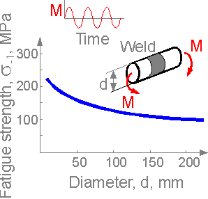 Fatigue
strength decreases for greater cross-section due to larger number of
surface defects and lower ability to deform plastically.
Fatigue
strength decreases for greater cross-section due to larger number of
surface defects and lower ability to deform plastically.
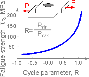 Loading
with negative cycle parameter R leads to increased local plastic
deformation and faster crack initiation. Fatigue strength is lower at
negative cycle parameter R.
Loading
with negative cycle parameter R leads to increased local plastic
deformation and faster crack initiation. Fatigue strength is lower at
negative cycle parameter R.
8.8 Fracture
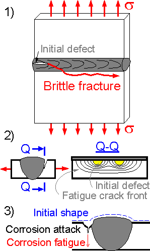 There
are three basic fractures connected with welded structures:
1)
brittle fracture: fast crack propagated from a welding defect into a
heat-affected zone, usually occurring within a second;
2)
fatigue fracture: fatigue crack growing slowly from welding defects
under cyclic loading;
3) corrosion fatigue: a crack propagated
by joint action of corrosion (local embrittlement) and cyclic
loading.
There
are three basic fractures connected with welded structures:
1)
brittle fracture: fast crack propagated from a welding defect into a
heat-affected zone, usually occurring within a second;
2)
fatigue fracture: fatigue crack growing slowly from welding defects
under cyclic loading;
3) corrosion fatigue: a crack propagated
by joint action of corrosion (local embrittlement) and cyclic
loading.
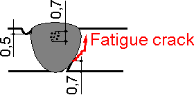
 For
complex structures, the trajectory of a fatigue crack can be curved.
A fatigue crack initiates from or tends to zones of maximum tensile
stress. The strongest welded structures have the smallest
concentration of welding defects and residual stress in the most
highly loaded zones.
For
complex structures, the trajectory of a fatigue crack can be curved.
A fatigue crack initiates from or tends to zones of maximum tensile
stress. The strongest welded structures have the smallest
concentration of welding defects and residual stress in the most
highly loaded zones.
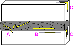 Some
welding defects can be observed at the weld surface. Defects in welds
have different geometry and location:
A. Hot cracks are
usually curved and open.
B. Cold cracks are usually straight.
C. Lamellar cracks are perpendicular to the thick plate
surface.
Some
welding defects can be observed at the weld surface. Defects in welds
have different geometry and location:
A. Hot cracks are
usually curved and open.
B. Cold cracks are usually straight.
C. Lamellar cracks are perpendicular to the thick plate
surface.
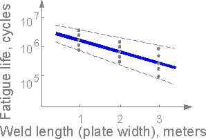 Scale
effect. For wider welds there is a higher probability of weld defects
and fatigue cracks. Fatigue life decreases with weld size
increase.
Scale
effect. For wider welds there is a higher probability of weld defects
and fatigue cracks. Fatigue life decreases with weld size
increase.