

7.6 Corrosion of metals and alloys
The
electrochemical series ranks the general resistance of metals to
corrosion. The more negative the standard Emf (Electromotive force)
potential, the more easily the material will oxidize.
The
monocrystal structure shows a higher resistance to corrosion than the
same metal with polycrystalline structure. The smaller the size of
grains, the more the material is prone to corrosion damages.
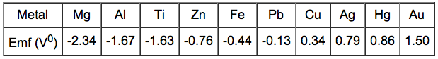
 If
two metals are electrically connected and immersed in a solution of
their own ions the EMF potential determines which material will
corrode. Iron dissolves in the electrolyte because iron has electrode
potential (-0.44 V) lower than that of copper (0.33 V). Consquently,
the copper deposits on the cathode. The magnitude of the voltage
driving the dissolution of iron is found to be:
If
two metals are electrically connected and immersed in a solution of
their own ions the EMF potential determines which material will
corrode. Iron dissolves in the electrolyte because iron has electrode
potential (-0.44 V) lower than that of copper (0.33 V). Consquently,
the copper deposits on the cathode. The magnitude of the voltage
driving the dissolution of iron is found to be:
DV = V1 - V2 = 0.34 - (-0.44) = 0.78 V
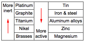 Galvanic
corrosion occurs when dissimilar metals are placed in assembly within
a corrosive electrolyte (e.g. sea water). This results in one of the
metals becoming anodic and corroding at faster rate than normal. The
other metal is the cathode responds with a decrease in corrosion
rate. The Galvanic series is useful for selecting materials to be
joined. Materials towards the bottom of the table are more active
(anodic) and will corrode at a faster rate than those above them. In
addition, the closer two metals are in the table the weaker the
corroding effect.
Galvanic
corrosion occurs when dissimilar metals are placed in assembly within
a corrosive electrolyte (e.g. sea water). This results in one of the
metals becoming anodic and corroding at faster rate than normal. The
other metal is the cathode responds with a decrease in corrosion
rate. The Galvanic series is useful for selecting materials to be
joined. Materials towards the bottom of the table are more active
(anodic) and will corrode at a faster rate than those above them. In
addition, the closer two metals are in the table the weaker the
corroding effect.
 Corrosion
rate depends on the relative areas of the anode and cathode. When the
surface area of the anodic metal is smaller than that of the cathode
the resulting corrosion is rapid. Consequently, the corrosion rate is
slow when a larger anode is connected to a small cathode.
Corrosion
rate depends on the relative areas of the anode and cathode. When the
surface area of the anodic metal is smaller than that of the cathode
the resulting corrosion is rapid. Consequently, the corrosion rate is
slow when a larger anode is connected to a small cathode.
 The
bolt displayed under a constant load will corrode at a greater rate
than one that is unloaded. This is due to regions of a high local
stress being anodic to those of a lower stress. The combined action
of a sufficient applied tensile stress and an aggressive environment
can cause the cracking of a part.
The
bolt displayed under a constant load will corrode at a greater rate
than one that is unloaded. This is due to regions of a high local
stress being anodic to those of a lower stress. The combined action
of a sufficient applied tensile stress and an aggressive environment
can cause the cracking of a part.
 Areas
of metals subjected to cold working are rich in dislocations and
therefore constantly under stress. This results in them being anodic
to the less stressed regions and accelerates corrosion.
Areas
of metals subjected to cold working are rich in dislocations and
therefore constantly under stress. This results in them being anodic
to the less stressed regions and accelerates corrosion.
 The
flow of oxygen to the area under the gasket is restricted and
therefore its concentration is low. This area will be anodic and
corrode faster than the oxygen rich areas.
The
flow of oxygen to the area under the gasket is restricted and
therefore its concentration is low. This area will be anodic and
corrode faster than the oxygen rich areas.
 For
a given fatigue life the influence of a corrosive environment on the
fatigue strength of metals increases if the frequency decreases. This
means that a structure loaded at a lower frequency will sustain less
cycles to fracture at a given applied stress. The picture shows S-N
curves of carbon steel tested in several mediums. All metals and
alloys cyclically loaded under a corrosive environment do not exhibit
a endurance (fatigue) limit. Which means that a structure exploited
under such conditions will finally break even if applied stress is
very low.
For
a given fatigue life the influence of a corrosive environment on the
fatigue strength of metals increases if the frequency decreases. This
means that a structure loaded at a lower frequency will sustain less
cycles to fracture at a given applied stress. The picture shows S-N
curves of carbon steel tested in several mediums. All metals and
alloys cyclically loaded under a corrosive environment do not exhibit
a endurance (fatigue) limit. Which means that a structure exploited
under such conditions will finally break even if applied stress is
very low.
7.7 Casting
 The
typical structure of a cast alloy consists of three zones:
1.
Chill zone - a few layers of fine equiaxed grains near the mold
walls.
2. Columnar zone - oriented grains grown in the direction
opposite of the heat transfer through the mold.
3. Equiaxed
zone - equiaxed grains of large size at the center of the
casting.
Depending on the processing conditions and material the
proportion of the columnar and equiaxed zones can be altered. Slow
cooling, adding the nucleating agents and agitating the melt
contribute to the growth of equiaxed zone. The enlarged columnar zone
is peculiar for pure metals.
The
typical structure of a cast alloy consists of three zones:
1.
Chill zone - a few layers of fine equiaxed grains near the mold
walls.
2. Columnar zone - oriented grains grown in the direction
opposite of the heat transfer through the mold.
3. Equiaxed
zone - equiaxed grains of large size at the center of the
casting.
Depending on the processing conditions and material the
proportion of the columnar and equiaxed zones can be altered. Slow
cooling, adding the nucleating agents and agitating the melt
contribute to the growth of equiaxed zone. The enlarged columnar zone
is peculiar for pure metals.
 The
greater the volume to surface area ratio, the slower a solid body
cools and solidifies.
Solidification time can be estimated by
Chvorinov's rule:
The
greater the volume to surface area ratio, the slower a solid body
cools and solidifies.
Solidification time can be estimated by
Chvorinov's rule:
TS = B(V/A)2,
where
V is the volume; A is the surface area; B is an empirical
constant.
 Patterns
very often have a temper on the vertical surfaces parallel to the
direction of withdrawal. This allows for an easy removal of the
pattern from the mold without any distortion or breaking of the mold
cavity. The angle of draft is normally 0.5-2o.
The angle depends mainly on the materials and processing
conditions.
Patterns
very often have a temper on the vertical surfaces parallel to the
direction of withdrawal. This allows for an easy removal of the
pattern from the mold without any distortion or breaking of the mold
cavity. The angle of draft is normally 0.5-2o.
The angle depends mainly on the materials and processing
conditions.
 Materials
with a short temperature range of crystallization (eg. pure metals or
eutectic alloys) tend to form a large concentrated shrinkage cavity
(right). The castings of alloys with a large freezing range have
porosity dispersed in the bulk of the material (left).
Materials
with a short temperature range of crystallization (eg. pure metals or
eutectic alloys) tend to form a large concentrated shrinkage cavity
(right). The castings of alloys with a large freezing range have
porosity dispersed in the bulk of the material (left).
 The
fluidity is the capability of material to flow into mold cavities
prior to solidification. The fluidity of pure metals and eutectic
alloys is higher than that of hypoeutectoid or hypereutectoid
alloys.
The
fluidity is the capability of material to flow into mold cavities
prior to solidification. The fluidity of pure metals and eutectic
alloys is higher than that of hypoeutectoid or hypereutectoid
alloys.
 Risers
are used to compensate for the shrinkage of molten metal during
solidification and to avoid the formation of a shrinkage cavity
within the casting. The shrinkage cavity forms into the riser because
it is the last part solidified in the mold. The risers are usually
located over the center of the heaviest sections of castings.
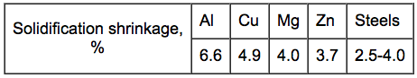
The
riser must be large enough to feed the shrinkage in the casting.
Solidification shrinkage varies for different metals and
influences the size of the risers.
Risers
are used to compensate for the shrinkage of molten metal during
solidification and to avoid the formation of a shrinkage cavity
within the casting. The shrinkage cavity forms into the riser because
it is the last part solidified in the mold. The risers are usually
located over the center of the heaviest sections of castings.
The
riser must be large enough to feed the shrinkage in the casting.
Solidification shrinkage varies for different metals and
influences the size of the risers.
Permanent mold casting vs Sand casting:
Increased dimensional accuracy and smoother surfaces; A new mold to produce every part is avoided; Increased mechanical properties due to a fine grain structure; Less time to cast a part; Shape and size of castings are limited; Not suitable for metals with a low fluidity.