

5.3 Hooke's law
 For
elastic deformations the normal stress is directly proportional to
strain. The ratio of axial stress/strain is a constant. This constant
is known as Young's modulus or modulus of elasticity E. Young's
modulus is directly proportional to the axial stress and inversely
proportional to the axial strain.
For
elastic deformations the normal stress is directly proportional to
strain. The ratio of axial stress/strain is a constant. This constant
is known as Young's modulus or modulus of elasticity E. Young's
modulus is directly proportional to the axial stress and inversely
proportional to the axial strain.
 For
three-dimensional stress state the formulas include more than one
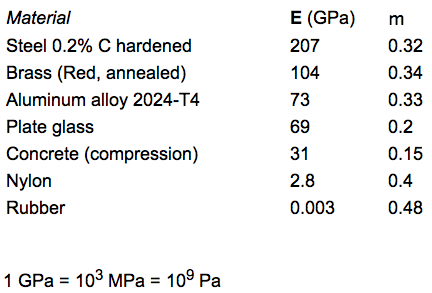
stress component. The expressions for isotropic elastic body include
three elastic constants of material: modulus of elasticity E,
Poisson's ratio m and shear modulus G. The elastic constants are
characteristics of the material. They do not depend on the shape or
size of the specimen.
The shear modulus G can be expressed
by the first two elastic constants. There are only two constants that
are independent parameters for an isotropic material.
For
three-dimensional stress state the formulas include more than one
stress component. The expressions for isotropic elastic body include
three elastic constants of material: modulus of elasticity E,
Poisson's ratio m and shear modulus G. The elastic constants are
characteristics of the material. They do not depend on the shape or
size of the specimen.
The shear modulus G can be expressed
by the first two elastic constants. There are only two constants that
are independent parameters for an isotropic material.
 Poisson's
ratio m characterizes transverse deformation under axial tension or
compression. It is a dimensionless parameter. For m=0.3, axial
tension of 10% corresponds to a transverse compression of
3%.
Poisson's
ratio m characterizes transverse deformation under axial tension or
compression. It is a dimensionless parameter. For m=0.3, axial
tension of 10% corresponds to a transverse compression of
3%.
 The
expressions show another form of the Hooke's law. Normal stress sx
depends on all three linear components of strain ex,
ey
and ez.
The
expressions show another form of the Hooke's law. Normal stress sx
depends on all three linear components of strain ex,
ey
and ez.
 Volume
expansion e characterizes an increase of an element size, not a
change of its shape. It depends on the linear strains only. The
volume expansion e can be defined by the elastic constants of the
material E, m and the sum of the normal stresses sx,
sy
and sy.
Volume
expansion e characterizes an increase of an element size, not a
change of its shape. It depends on the linear strains only. The
volume expansion e can be defined by the elastic constants of the
material E, m and the sum of the normal stresses sx,
sy
and sy.
5.4 Plane problems
 There
are two special states of stress: plane stress for thin plates and
plane strain for thick plates.
For plane stress there are
four non-zero strain components (ex
, ey
, ez
, gxy
) and three non-zero stress components (sx
, sy
, txy
). The plane stress is typical for thin-walled structures such as in
airplane wings.
For plane strain there are three non-zero
strain components (ex,
ey,
gxy)
and four non-zero stress components (sx,
sy,
sz,
txy).
Plane strain is typical for thick plates.
There
are two special states of stress: plane stress for thin plates and
plane strain for thick plates.
For plane stress there are
four non-zero strain components (ex
, ey
, ez
, gxy
) and three non-zero stress components (sx
, sy
, txy
). The plane stress is typical for thin-walled structures such as in
airplane wings.
For plane strain there are three non-zero
strain components (ex,
ey,
gxy)
and four non-zero stress components (sx,
sy,
sz,
txy).
Plane strain is typical for thick plates.
 There
are two equilibrium equations that must be satisfied for absence of
mass forces. Elastic plates have stress fields that satisfy Hooke's
law and the strain compatibility equations. The two stress components
shown correspond to an embedded beam with a force applied to the
right end. The equilibrium equations help solve the plane problems of
the theory of elasticity.
There
are two equilibrium equations that must be satisfied for absence of
mass forces. Elastic plates have stress fields that satisfy Hooke's
law and the strain compatibility equations. The two stress components
shown correspond to an embedded beam with a force applied to the
right end. The equilibrium equations help solve the plane problems of
the theory of elasticity.
 There
are two inclined principle planes where there is no shear stress and
normal stresses (s1
and s2)
are at a maximum.
There
are two inclined principle planes where there is no shear stress and
normal stresses (s1
and s2)
are at a maximum.
 Principle
axes are inclined 45o
to the direction of shear stress t for pure shear. Indication A is
negative. There are zero indications for B and D.
Principle
axes are inclined 45o
to the direction of shear stress t for pure shear. Indication A is
negative. There are zero indications for B and D.
 The
figure shows typical stress patterns for sx,
sy
and txy.
The normal stress sx is usually higher than other stress components
for a long beam, where Length >> Height.
The
figure shows typical stress patterns for sx,
sy
and txy.
The normal stress sx is usually higher than other stress components
for a long beam, where Length >> Height.
 There
is concentration of shear stress in the area where force is applied.
Shear stress is equal to zero at the surface and is at a maximum in a
neighboring region.
There
is concentration of shear stress in the area where force is applied.
Shear stress is equal to zero at the surface and is at a maximum in a
neighboring region.
 Normal
stress sy
at axis x can be positive outside the zone of compression. Here, the
compressive stress is significantly higher than the tensile
stress.
Normal
stress sy
at axis x can be positive outside the zone of compression. Here, the
compressive stress is significantly higher than the tensile
stress.
 Saint-Venant's
principle. At a distance equal to width of the beam (2a), the maximum
stress does not exceed the nominal stress by 4%. The stress pattern
becomes practically uniform.
Saint-Venant's
principle. At a distance equal to width of the beam (2a), the maximum
stress does not exceed the nominal stress by 4%. The stress pattern
becomes practically uniform.