

Figure 2-10 Chapter 3 Main Components
1. Diesel Engine
For detailed description of diesel engine, refer to the engine user’s manual provided with engine.
Precaution:
1.1 When the ambient temperature is lower than the freezing point and no antifreeze is added in the coolant, it is necessary to open the drain plugs at engine block, water pump, engine oil cooler, coolant tank and torque converter cooler to drain the water out so as to prevent the parts from cracking if the machine is to be shipped for long distance or stopped for long time.
1.2 In case oil is found in coolant or water is found is oil pan, check the diesel engine and the cooler element of torque converter to see if it is damaged.
2. Torque Converter
Single stage four-element torque converter (see figure 3-1) is installed between engine and transmission.
2.1 Features:
2.1.1 It can automatically adjust output torque and rotational speed which enables loader to automatically modify speed and rimpull according to the condition of road and force of resistance, and meet the requirements for various working conditions. After putting into gear, speed can be changed automatically and steplessly between start and the max speed in this gear. With stable starting, it can achieve good acceleration performance.
When gradient or sudden road obstacle is encountered, it can automatically slow down and increase the rimpull without changing gear and run with minimum speed to get over obstacles. After external resistance decreased, it can automatically accelerate quickly to work efficiently.
At loading, it can reach the material pile with fast speed, and automatically decelerates along with resistance increasement to increase the rimpull for ensuring penetration. Therefore, due to above advantages, average running speed of loader is higher than usual, cycle time is shortened and productivity is improved.
2.1.2 With two turbines, two speed ranges can be automatically realized from low speed/heavy load to high speed/light load. This obviously reduces gearing in transmission and simplifies the structure, therefore cost is lowered.
2.1.3 With high torque conversion ratio and wider effective area, loader can sufficiently utilize power of engine to bring its rimpull and speed to play with good economical performance.
2.1.4 Torque converter adopts liquid as transfer medium that replace main clutch. So working oil can absorb and eliminate vibration and impact from both diesel and external load, and protect engine and powertrain system to extend the lifetime of loader and reduce maintenance workload and expense. When external load is suddenly increased or unable to overcome, engine will not shut down which ensure proper work of each oil pump and improve security and reliability of loader.
2.1.5 As vibration and impact are eliminated and no main clutch is needed, times for gear changing is reduced, and the operator can work easily.
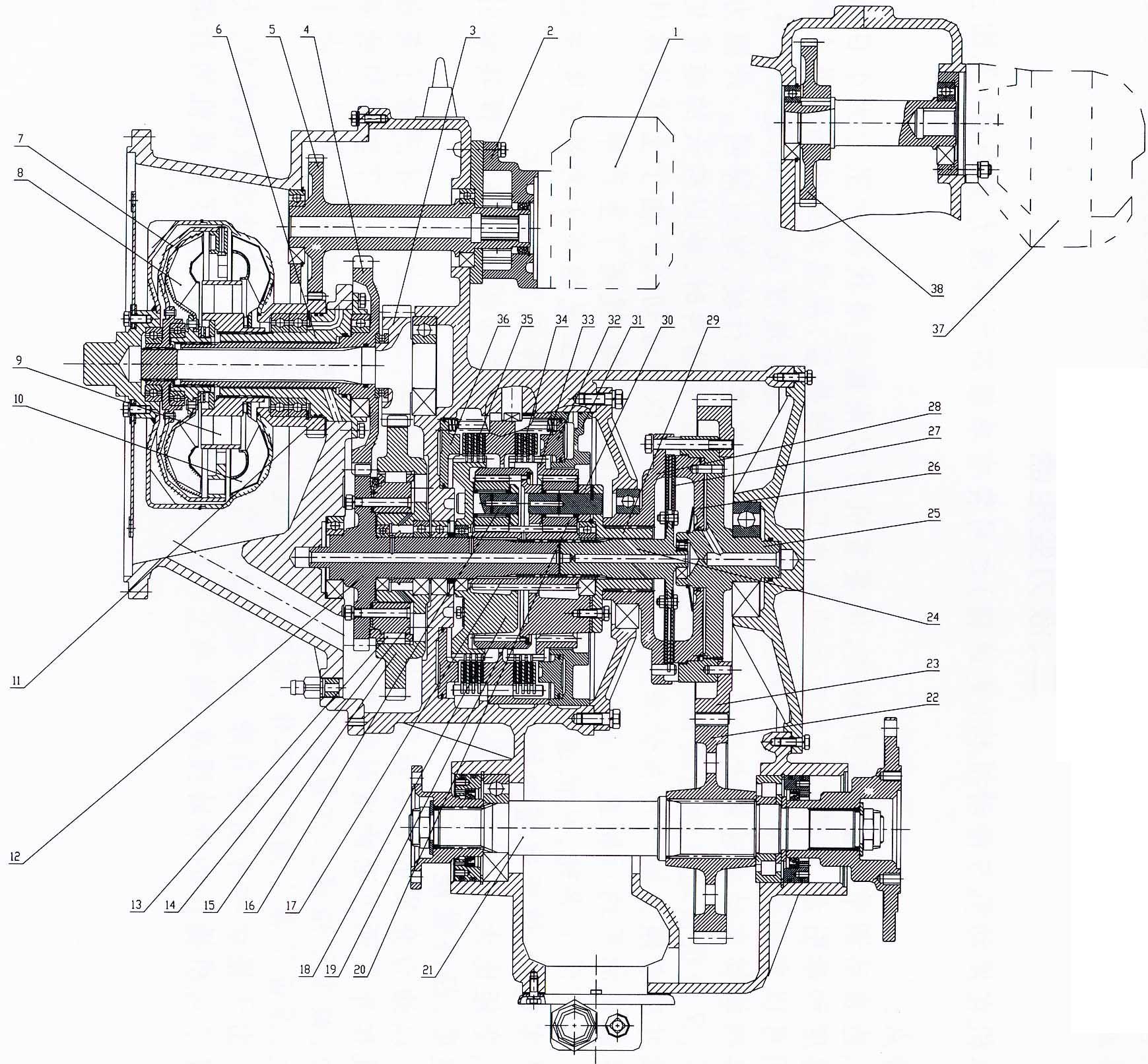
Figure 3-1 Torque converter & transmission
1. Implement pump |
14. Large overrunning cam |
27. Direct speed friction disc |
2. Transmission pump |
15. Large overrunning outer gear |
28. Direct speed pressure disc |
3. First stage input gear |
16. Reverse planet gear |
29. Direct speed connecting disc |
4. Second stage input gear |
17. Sun gear |
30. Speed I planet carrier |
5. Shaft gear |
18. Reverse planet carrier |
31. Speed I oil cylinder |
6. Guide wheel seat |
19. Reverse ring gear |
32. Speed I piston |
7. First stage turbine |
20. Speed I planet gear |
33. Speed I ring gear |
8. Second stage turbine |
21. Output shaft |
34. Speed I friction disc |
9. Guide wheel |
22. Output shaft gear |
35. Reverse friction disc |
10. Pump wheel |
23. Intermediate output gear |
36. Reverse piston |
11. Transfer gear |
24. Direct speed shaft |
37. Steering pump |
12. Intermediate input shaft |
25. Direct speed oil cylinder |
38. Steering pump driving gear |
13. Large overrunning roller |
26. Direct speed piston |
|
2.2 Working principle:
Torque converter is formed by four working impeller: pump wheel (10), first stage turbine (7) and idler (9).Working chamber is filled with working oil. Function of pump wheel (10) is to convert mechanical energy generated by engine to kinetic energy of liquid. It is driven by engine and rotates with the same speed as engine that forces the oil in chamber to push the turbine with tremendous speed and pressure.
Two turbines (7) and (8) absorb energy and convert it into mechanical energy and transfer the power to the large overrunning clutch via gears with rotation of n1 and n2 respectively. Idler (9) is fixed and non-rotated. When fluid pushes the vane of idler (9), the idler generates a reverse torque with same strength but opposite direction and reflect it to turbine via liquid that changes the output torque by turbine.
Each vane of the four working wheels has certain shape and inlet & outlet angle which causes fluid to pass in and out each wheel through specified channels. But due to speed of impeller is controlled by throttle and could be high or low, speed of turbine can be fast or slow or even stopped (for example, during starting or braking, wheel is not rotated) along with speed changes of external load (feedback via axle and transmission) applied on output shaft. So the fluid enters each working wheel in variable speed, pressure and action angle.
The torque generated by pump and reflected by idler also varies. When pump wheel torque acquired by turbine via liquid is in positive direction, turbine output torque will increase. When it is in reverse direction, the output torque will decrease. The fixed idler makes it possible for the torque converter to change torque.
When loader is traveling at high speed or external resistance is small, the second stage turbine of torque converter works individually. When external resistance increases and the vehicle speed decreases (engine speed keeps constant), both first stage and second stage turbines will work.
2.3 The inlet oil pressure of torque converter is 0.3-0.45Mpa, lubricant pressure is 0.10-0.20Mpa. The pressure was preset by the manufacturer before shipment. Customers do not adjust it.
2.4 For structure and working principle, refer to the section “Transmission”.