

Figure 3-18 Bucket dump
Overload complementary valves
These valves are mounted in oil lines at the front/rear chamber of tilt cylinder (at the customer's option). Its function is to eliminate the oil blocking or negative pressure in cylinder caused by external shock to the bucket or interference between bucket and other mechanism.
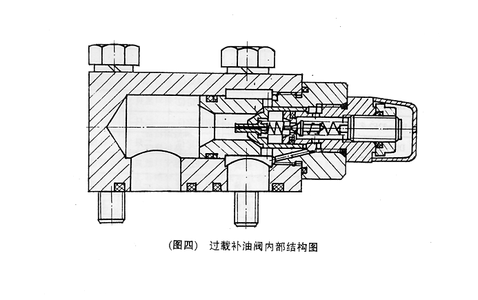
Figure 3-19 Overload complementary valve
7.2.2 Oil tank, see figure 3-20,It is shared by the implement system and steering system. There are three filters in it. The volume of the tank is 220 liters
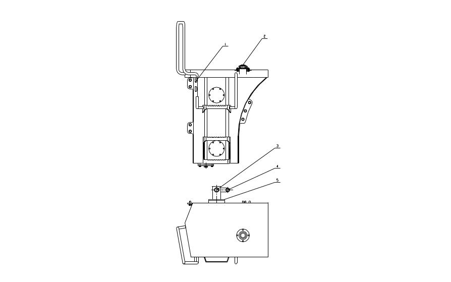
Figure 3-20 Implement oil tank
1. Oil viewer 2. Oil filler 3. To inlet of implement pump
4. To inlet of steering pump 5.Oil suction flange
7.2.3 Implement pump, See Figure 3-21,
Model: CBG92050
Operating pressure: 16MPa
Oil mass: 220 L/M
Rated RPM: 2200 r/m
The oil pump is connected to the variant pump and fastened on the transmission body, and driven by the engine through gears. CBG pump is an external gear pump, and it is composed of one meshed pair of driving gear and driven gear, pump body, side plate, shaft, seals etc.
When the driving gears rotate, they rotate the driven gears. The place the gear teeth move backward is the oil suction chamber, while the place the gear teeth move forward is the oil compression chamber. The oil suction chamber and the compression chamber are separated by the gearing line of the driven gear, the radial clearance and the end clearance. When the driving gears rotate following the arrow, the oil suction chamber is made up of the surface of gear 8,9,10,1.1’,10’,9'and the pump body and inner face of the pump cover. When the gears rotate, the space that gear 8,9 cover is larger than that gear 1, 1’ cover. Hence the space of the suction chamber becomes larger and forms part vacuum, the hydraulic oil in the tank is compressed to the suction chamber under the atmospheric pressure, which is the procedures of suction.(See Figure3-22)
Figure 3-21 Implement pump
1.Driven gear |
2.Front pump cover |
3.Rolling bearing34108K |
4.Oil seal SG38×58×12 |
5.Driving gear |
6.Pump body |
7.Side plate |
8.Seal ring |
9.Pin |
10.Setting screw |
11.O-ring |
12.O-ring and pad |
Displacement chamber
Oil suction chamber
Figure 3-22 Working principle of implement pump
7.2.4 Lift cylinder and tile cylinder
See Figure 3-23 and Figure3-24
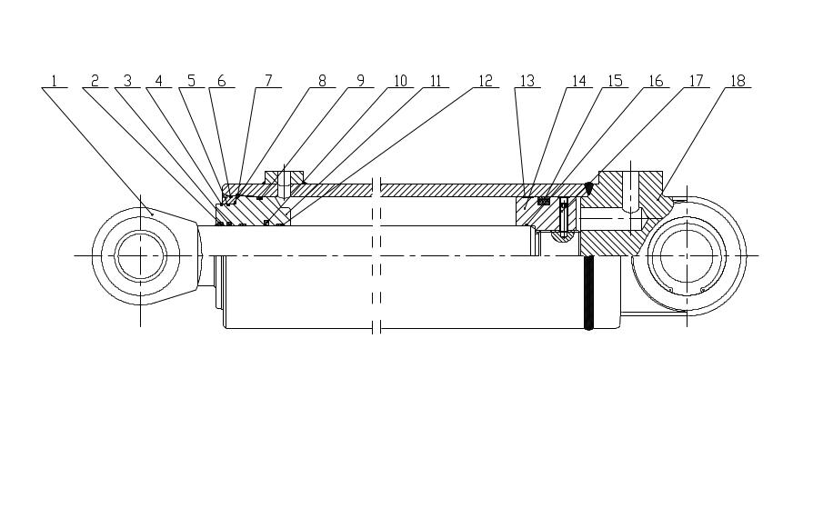
Figure 3-23 Lift cylinder
1. Piston rod 2. Dust ring 3. Piston rod seal ring
4. Snap ring for shaft 5. O-ring 6. O-ring
7. Spring retainer 8. Ring 9. O-ring
10. Piston rod damp ring 11. Direction bush 12. Piston rod direction guide ring
13. Piston support ring 14. Piston 15. Piston seal ring
16. O-ring 17. Stud 18. Cylinder body
Figure 3-24 Tilt cylinder
1.Knuckle bearing |
2.Castle nut |
3.Seal |
4.Cylinder rod |
5.Piston rod |
6.Bush |
7.Seal |
8.Dust ring |
|