Figure 3-7 Structure of vle-150 priority valve
1.Relief valve 2.Control spring 3.Stem 4.Valve body
Steering gear (Figure 3-8)
Nominal pressure: 20MPa
Theoretical displacement: 800ml/r
N
Complementary valve Inlet check
valve
F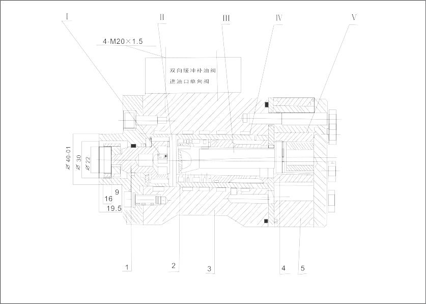 igure
3-8 Steering gear
igure
3-8 Steering gear
I. Spring II. Pin III. Connecting shaft IV. Control/amplification valve V. Cycloidal gearing
1.Spool 2.Valve sleeve 3.Valve body 4.Rotor 5.Stator/rotor
Main components and working principle:
The control/amplification valve controls the flowing direction and amplifies the flow. The cycloidal gearing composed of rotor and stator works as metering pump to ensure that the oil output is proportional to the turning angle of steering wheel. The pin and connecting shaft connect the control/amplification valve and the rotor of cycloidal gearing so as to compose a mechanical feedback. The spring makes the spool and valve sleeve of the control/amplification valve pass the dead point to be positioned at the middle.
When and steering gear is at the neutral position, the oil from the priority valve returns to the oil tank via the return port.
When the steering gear is turned with the steering wheel, the oil from the priority valve is divided into two branches: the minority flows to the cycloidal gearing via the control/amplification valve to push the rotor to turn with the steering wheel. The flow through the cycloidal gearing is proportional to the turning speed of the steering wheel. The faster the steering wheel turns, the more the flow is. The majority of the oil flows directly to the steering cylinder to realize the turning of frames. The flow is controlled by the mechanical feedback of pin, connecting shaft, control/amplification valve and cycloidal gearing. It is proportional to the turning speed of steering wheel. The faster the steering wheel turns, the faster the vehicle turns.
5.2.3 Steering cylinder
Refer to Figure 3-9 for its structure.
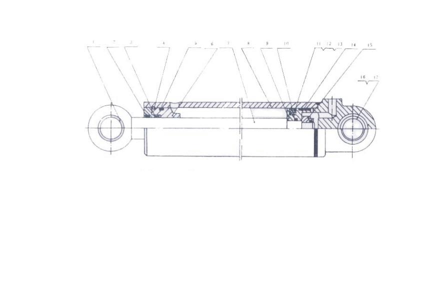
Figure 3-9 Steering cylinder
1.Sleeve |
4.Wired check ring |
7.Piston rod |
10.O-ring |
13.Check ring |
16.Knuckle bearing |
2.Dust ring |
5.O-ring |
8.Cylinder block |
11.Washer |
14.support ring |
17.Check ring |
3.Seal |
6.Guide sleeve |
9.Piston |
12.Seal |
15.Lock nut |
|
5.3 Maintenance of steering system
The hydraulic oil in the steering system should be kept clean. Change oil and clean the system once every half year.
Check and clean the components in steering system, e.g. steering gear, priority valve and steering cylinder once a year. Pay attention to prevent the parts from being damaged when disassembling/assembling the parts.
6. Implement and frames
6.1 Implement
The implement consists of bucket, linkage, lift arm, tilt lever, etc. See Figure 3-10.
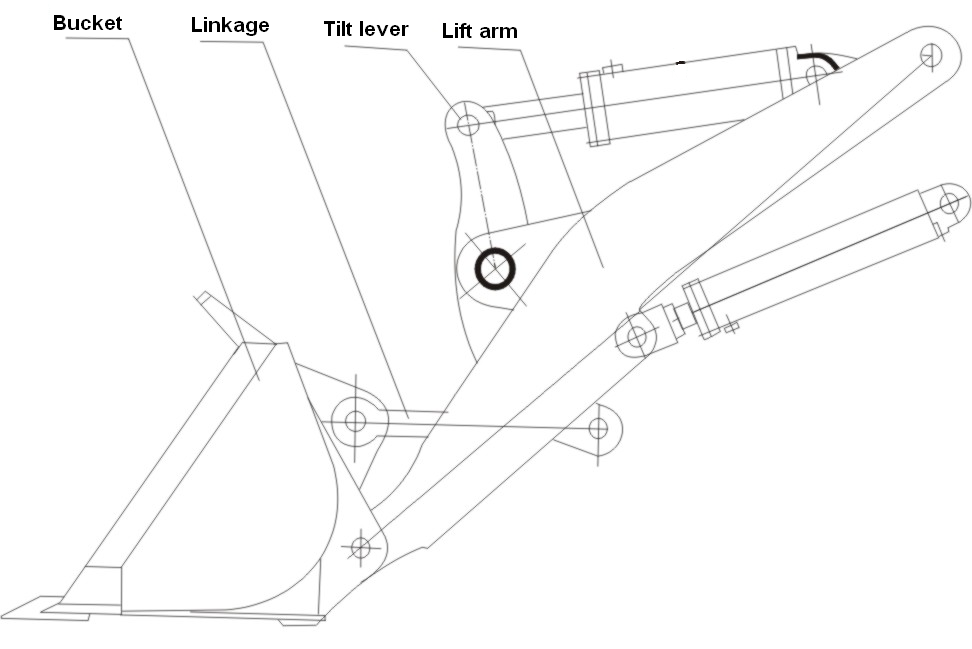
Figure 3-10 Implement
This machine has Z-bar linkage. It provides higher dumping height, stronger breakout force, larger rollback angle, better leveling, easier loading and keeping of material. When the bucket is lowered from the dumping height to the lowest position, it will be automatically be leveled.
The lift arm is made of steel plate. Its rear end is supported on the front frame; its front end is connected to the bucket. The lift cylinder is connected at its middle. When the lift cylinder extends or retracts, the lift arm rotates around its rear pin to realize lifting or lowering.
The middle of the tilt lever is connected with the lift cylinder. When the tilt cylinder extends or retracts, the tilt lever rotates around its middle point so as to make the linkage turn the bucket. Its rotation is combined with the lifting/lowering of lift arm and the traveling of vehicle for various tasks.
The bottom of the bucket is flat. Teeth are installed on the cutting edge with bolts. The tooth is replaceable when it is worn. New cutting edge can be mounted after the old one is cut.
There are 7 hitch points in the implement system, e.g. between bucket and lift arm, between bucket and linkage, between linkage and tilt lever, between tilt lever and lift arm, between lift arm and frame, between lift arm and cylinder, between tilt lever and cylinder. The mating clearance is 0.06 – 0.22mm. Abrasion will be caused between pins and bushes. Bush or pin should be replaced if the clearance is more than 0.6 – 0.7mm.
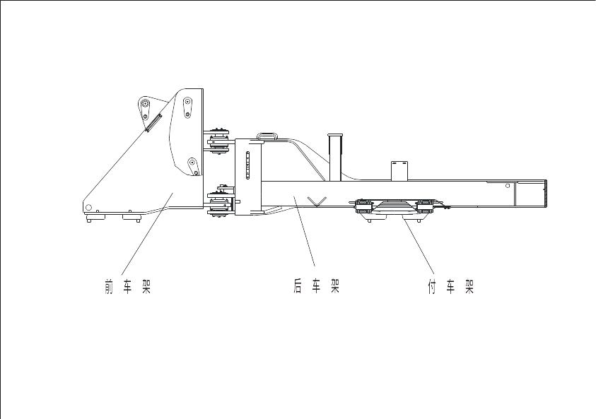
6.2 Frame
Frames (front frame and rear frame) are the base parts on which all components are installed. There is an oscillating suspension on the rear frame. See Figure 3-11.
The front and rear frames are linked with hitch pins. The front frame is supported on the front axle. The implement is supported by the front frame. The rear frame is connected with the rear axle via the oscillating suspension. Engine, torque converter, transmission, cab, control mechanism and so on are on the rear frame.
R