

6. Hydraulic steering system
Item |
Description |
Specification |
1 |
Type |
Hydraulic steering with load sensing |
2 |
System pressure |
16MPa |
3 |
Steering pump |
CBG92063 |
Flow rate |
138L/min |
|
4 |
Turning angle |
35° leftward/rightward |
5 |
Number of steering cylinders- bore×stroke |
2-φ90×340 |
7. Implement hydraulic system
Item |
Description |
Specification |
1 |
Implement pump |
CBG92050 |
2 |
Rated RPM |
2200 r/m |
3 |
Flow rate |
110 L/min |
4 |
System operating pressure |
16MPa |
5 |
Distributor valve |
DF32 |
6 |
Number of lift cylinders-bore x stroke |
2-φ125×761 |
7 |
Number of tilt cylinders- bore x stroke |
1-φ160×495 |
8. Electrical system
Item |
Description |
Specification |
1 |
System voltage |
24V |
2 |
Battery |
N12(2 pieces) |
3 |
Single-wire system |
Cathode connected to iron |
4 |
Engine cranking voltage |
24V |
Chapter 2 Operation
1. Operation mechanism and instruments
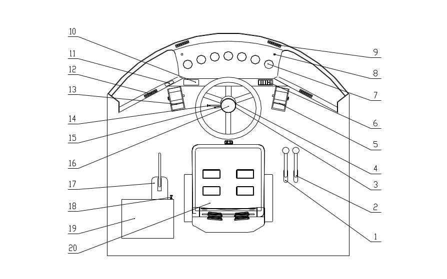
Figure 2-1 Operation mechanism and instruments
1.Tilt control lever 2.Lift control lever 3.Electrical lock 4. Turning lamp/headlight/instrument lamp switch 5. Throttle pedal 6. Switch (dome lamp, working lamp, rear working lamp, heating & air conditioning system switch) 7. Instruments (engine oil gauge, engine coolant temperature gauge, torque converter oil temperature gauge, transmission oil temperature gauge, brake air pressure gauge, hour meter, ammeter) 8. Turning indicator 9. Defrost vent
|
10. Radio and record set(optional) 11. Fuse box 12. Vent 13. Service brake pedal 14. Speed selector 15.Wiper switch 16. Horn button 17. Parking brake control 18.Shutoff switch 19.Tool box 20.Seat |
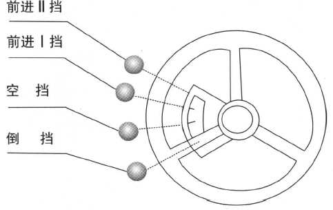

Figure 2-2 Speed Selector

Figure 2-3 Implement control
Stop
Release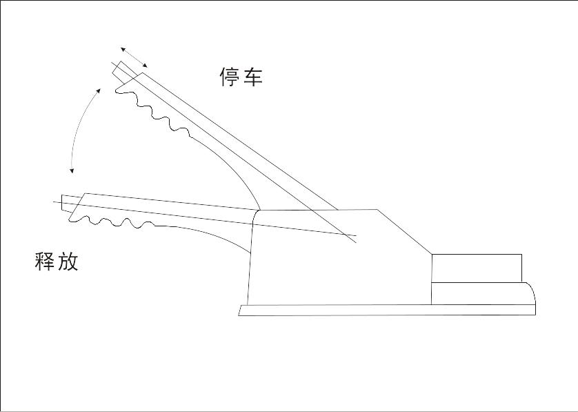
Figure 2-4 Parking brake control lever
2. New vehicle break in
2.1 Precaution on new vehicle break-in
2.1.1 The break-in must be done for 12 hours, equally for each speed (I forward, II forward and reverse).
2.1.2 During the break-in period, the loaded weight must not exceed 70% of the rated load.
2.1.3 Pay attention to the lubrication. Change or add grease according to the prescribed time.
2.1.4 Pay attention to the temperature of transmission, torque converter, front/rear axles, brake disc and brake drum. Do troubleshooting if overheat occurs.
2.1.5 Check the tightness of bolts and nuts on each part.
2.1.6 During the brake-in period, it is better to load incompact material, and the operation should be gentle.
2.2 Perform the following work after 8 hours of break-in.
2.2.1 Completely check the tightness of bolts and nuts on each part, especially those on cylinder cap, exhaust pipe, front and rear axles, rim and drive shaft.
2.2.2 Clean the primary and fine oil filters, and fuel filter.
2.2.3 Check the tension of fan belt. Check if the battery is properly charged by generator
2.2.4 Check the specific weight and the remaining amount of battery liquid. Make sure that the battery terminal is firmly connected.
2.2.5 Check the transmission oil level.
2.2.6 Check the airtightness in hydraulic system, pneumatic system and brake system.
2.2.7 Check the firmness of fasteners on operation lever and throttle lever.
2.2.8 Check the connection in electrical system, the condition of generator, lighting and turning indicators.
2.3 After the break-in period is finished, perform the following work.
2.3.1 Clean the screen in transmission oil pan and change new oil.
2.3.2 Change engine oil.