

Figure 3-28 Booster pump
E. Disc brake
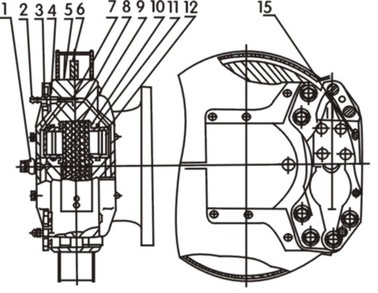
Figure 3-29 Disc brake
1.Fluid inlet 2.Air bleed nozzle 3.Connector 4.O-ring
5.Inner caliper 6.Brake disc 7.O-ring 8.Outer caliper
9.Brake pad 10.Dustproof cover 11.Seal 12.Piston 15.Bolt pin
Working principle:
There are two cylinders in a brake. The calipers are fixed on the axle housing. The disc is mounted on the hub and turns with the wheel. Two pairs of calipers are mounted for one wheel (totally 8 pairs for the whole machine). In each pair of caliper, there are two pairs of cylinder piston.
At braking, the hydraulic oil from the booster pump flows to each piston cylinder via the oil pipes and the oil channels in the inner/outer calipers to push the piston (12) and the brake pad (9) onto the disc brake. The wheel will be decelerated and stopped.
When the brake is released, the brake pad is returned by the slight swing of disc. The brake pads contact the disc (not pressed) during travel. The heat generated during long time friction will make the temperature of brake fluid go up. “Cavitation” may be caused. It is necessary to bleed the air from the brake so as to ensure proper performance of the brake.
8.2.3 Operation and maintenance of service brake
Periodic and correct maintenance are very important for ensuring braking performance and vehicle safety.
Frequently check for leakage in the system and/or looseness at the connecting parts. No air leakage is permitted in the air pipes, and no oil leakage is permitted in the oil pipes. When the brake disc are abased to two third, please change it in time.
The brake fluid should be synthetic brake fluid 719 that is resistant to high temperature. Only vegetable based brake fluid can be used if the brake fluid has to be changed. The remaining old fluid should be rinsed with new fluid before filling. Timely add the fluid to keep correct level. Use filter cup at filling. The fluid level should be 20 – 25mm from the filler. Mineral oil or water must not be mixed in the fluid, otherwise the rubber parts in the system may be easily damaged and the brake may become ineffective.
The air in oil lines may make bad effect to the brake performance. So air must be bled after replacement or service is done. The steps for air bleeding is as follows:
Wipe off the dirt on the pipes, oil container, oil filler and air bleed nozzle.
Fill the brake fluid in accordance with the requirements.
Start the engine. When the air pressure reaches 0.67 – 0.69MPa, stop the engine.
Connect a transparent plastic hose to the air bleed nozzle. Put the other end of the hose into the oil container.
Pump the brake pedal several times. Then depress and keep the brake pedal to its limit. Loosen the air bleed nozzles on the brakes of front/rear wheels to bleed the air until no air bulb can be seen in the fluid flowing out. Tighten the air bleed nozzle and release the brake pedal. Pay attention to the fluid level and fill additional fluid through the fluid cup as necessary to prevent the air from entering at bleeding.
Unscrew the drain plug on the bottom of air tank to drain the liquid when there is still pressure in the air tank after air bleeding. Otherwise, the air tank may be rusted and the rubber parts in the air pipes may be damaged.
Check the relief valve frequently to keep it in good condition and assure safety.
Check the pressurized container frequently. Replace the pressure controller if leakage or blocking is found;
Check the relief valve at least once a year to keep it in good condition. The rated operating air pressure is 0.784MPa;
Check the pressure gauge frequently. Replace it if leakage or malfunction is found.
The pressure gauges should be calibrated by the measurement authority at least once a year. Make sure it is in good condition.
Pay attention to following items when using air tank:
The life of air tank is five years if the machine is operated continually. The life will be shortened if the machine is stopped for long period. For example, if the machine is stopped for more than one year, the life of the air tank will be about three years. Replace with a new tank labeled by Longgong when the time expires.
Check the outer surface of air tank frequently. Remove the rust and paint it when rustproof coating is shed. Stop using and replace the air tank whenever flaw or deformation is found;
Do pressure-resistance test annually. The test pressure is 1.2Mpa. Pressure-resistance test is also necessary before reuse if the machine has stopped for three or more months.
8.3 Parking brake system
The parking brake system is applied when the vehicle is parked. It can also work as emergency brake and assure safety when the air pressure of wheel loader is too low.
8.3.1 Main parts and working principle
The parking brake system consists of parking brake, control lever and control flexible shaft, serving for a long-time park, which also named hand brake. The parking brake is self boosting two shoe internal expanding type, which is installed on the front outlet shaft of the transmission, also named transmission brake. (See Figure 3-30)
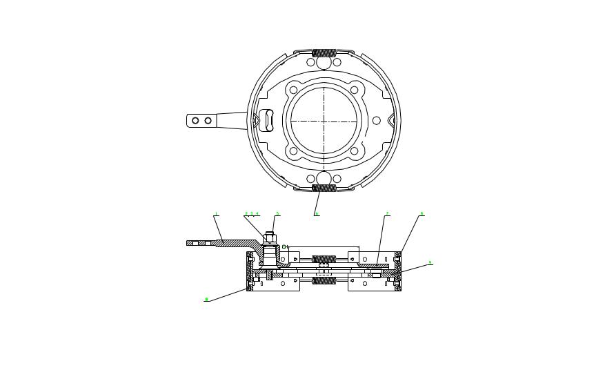
Figure 3-30 Hand brake
1.Drawbar |
3.Washer |
5.Rod shaft |
7.Brake system bracket |
9.Moveable plate |
2.Nut |
4.Washer |
6.Spring |
8.Right shoe assembly |
10. Left shoe assembly |
The working principle is to pull the control lever, to make the rod (8) move through control flexible shaft. Because of the deflexion of the involute cam of the rod end, the two brake shoes expand and compress on the inner circumference of the brake drum to achieve brake.
Attention :
The usually error might be caused by those as follow:
Friction plate (1) is worn, brake drum is cracked, surface is worn or scratched and bolt (7) is worn and loosened, etc.
If it is broken, please repair and change in time. If the friction plate is worn to 0.5mm from rivet head or severely heated or stained, it must be replaced. (Ordinary oil stain could be cleaned with petrol.) If the inner grooving of the brake drum is deeper than 1.5mm or severe worn and out of cylindricity, please repair or replace. After repairing, the error for bore cylindricity should be no more than 0.52mm, the runout of the working surface to transmission output shaft center line should be no more than 0.12mm and the kinetic balance value should be no more than 80g/cm
If the clearance for each pin is over 0.2mm, please replace.
After re-assembly, the clearance between brake shoe and brake drum could be adjusted by screwdriver, and the clearance range should be 0.3-0.5mm.It is requested that when the control lever works, the contact area of brake shoe and brake drum should be over 82% and the machine could be stop on a slope angled below 8 degree. After relief, the frication plate should be departed from the brake drum.
If it could not achieve the request by adjusting the lever, it should adjust the control flexible shaft: pull the hatch pin of the flexible shaft, adjust the U-fork, change the length of the shaft core, then using the adjustment lever to adjust to meet the request.