F Front frame Rear frame Oscillating suspension igure 3-11 Frames
7. Implement hydraulic system
7.1 Working principle
The implement hydraulic system is used for controlling the action of lift arm and bucket to satisfy the requirements of different task. The main components: fuel tank, oil pump, distributor valve, lift cylinder, tilt cylinder etc.
When the implement does not work, the pilot oil will flow to the distributor valve, and flow back to oil tank via the oil return chamber.
For dumping (digging) the bucket, control the tilt lever, pull (push). The deadweight of implement makes the oil flow to the rear chamber (front chamber) of tilt cylinder via implement valve so as to move the bucket forward (backward).
For lifting (lowering) the lift arm, control the lift lever, pull (push). The deadweight of implement makes the oil flow to the lower chamber (upper chamber) of lift cylinder via implement valve so as to move the lift up (down).
When the outside load is beyond lifting ability, or the piston of lift cylinder reaches the end, or the piston of tilt cylinder reaches the end, the system pressure increases to the set pressure, the overload valve will be opened for safety when the bucket encounters external shock or interferes with other parts.
From priority valve
Figure 3-12 Implement hydraulic system
1. Oil tank 2.Implement pump 3.Distributor valve
4. Lift cylinder 5.Tilt cylinder
When the front chamber oil temperature is beyond the set pressure, the pilot oil will open the relief valve and overflow back to oil tank via distributor valve. When the bucket need relocating, control the lift lever, push forward gear II, then the implement oil will flow into the upper/lower chambers of lift cylinder, and link the oil tank. The oil in the lift cylinder stays in low pressure position, the bucket is in the condition of free-floating, and the bucket will work close to the ground.
7.2 Structure and specifications of main parts
7.2.1 Distributor valve
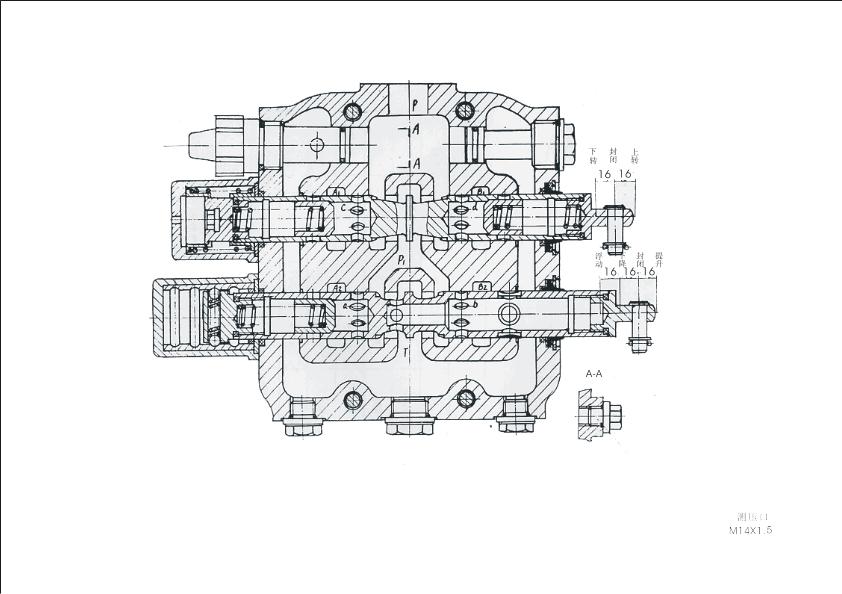
Figure 3-13 Distributor valve
The oil circuit for this valve is in series. Its function is to control the moving direction of the tilt cylinder and lift cylinder through changing the flowing direction of oil and make the bucket stay in a specific position for satisfying specific requirement of operation.(See Figure3-13).
The tilt directional control valve and the auxiliary directional control valve are 3-position and 6-port valve. They can make the bucket roll back, dump and hold.
The lift directional valve is a 4-position and 6-port valve. It can make the lift arm rise, hold, lower and float.
Relief valve is used to control the system pressure. If the system pressure is beyond the rated pressure, the valve will be opened and the oil will flow back to the oil tank to protect the hydraulic system.
Port P of distributor valve links to the implement pump and is the oil inlet port. The upper port links to the oil tank and is the oil return port. Chambers A and B link to the big and small chambers of tilt cylinder respectively. Chambers C and D link to the big and small chambers of lift cylinder respectively. The 7 oil sinks in the valve body are symmetrically arranged at the left and right. The relief channel at neutral position is with 3 grooves so that the hydraulic shock can be eliminated and the resistance for oil return is reduced.
Two check valves are mounted on both ends of the tilt valve spool, which are compressed on the valve body by Spring 39. There is another check valve on the left end of the lift valve spool, which is also compressed on the valve body. The check valve prevents the oil from flowing back to the oil tank during steering so that “nodding” can be avoided. Besides, the back pressure coursed during the oil return can make the system stable.
Neutral (hold)
The oil at both ends of the tilt and lift cylinders are blocked and stay in a certain position. At this moment, the oil from the pump returns to the oil tank through port P, II, III, IV, V and pipes. The relief valve is closed and the system is running idly.
Lifting
Move the lift valve spool rightward to close the chamber T. The hydraulic oil flows to Port “a” via Chamber P1, opens the check valve, and then flows to the lower chamber via port A2 to raise the lift arm. The hydraulic oil in the upper chamber flows back to oil tank via port B2, b and chamber T.
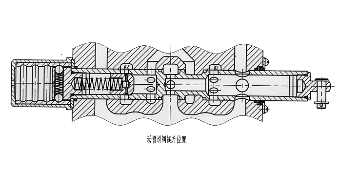
Figure 3-14 Lift valve spool in “Rise” position
Lowering
Move the lift valve spool leftward to close the chamber T. The hydraulic oil flows to the upper chamber via chamber P1, port “b” and B2 to lower lift arm. The hydraulic oil in the lower chamber flows through port A2 and “a” to open the check valve and flow back to oil tank.
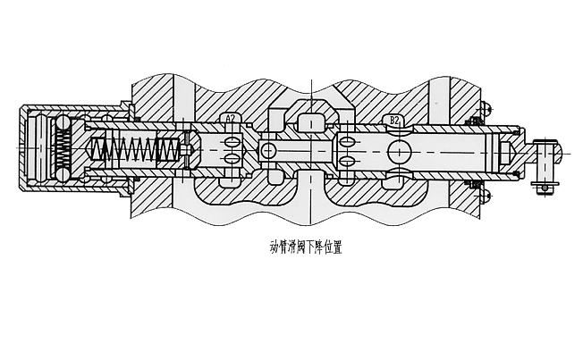
Figure 3-15 Lift valve spool in “Lower” position
Floating
Move the lift valve spool leftward (See Figure 3-16). At this moment, port A2 and B2 link to port “b” and chamber T, P1. The upper chamber and lower chamber are linked with each other and pressure is low. The cylinders are floating owing to the weight of implement and the acting force from the ground.
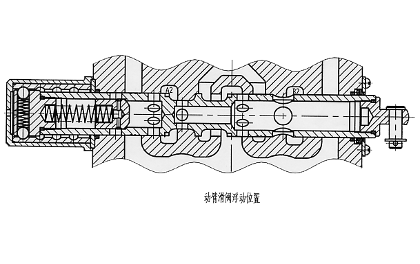
Figure 3-16 Lift valve spool in “Float” position
Bucket roll back
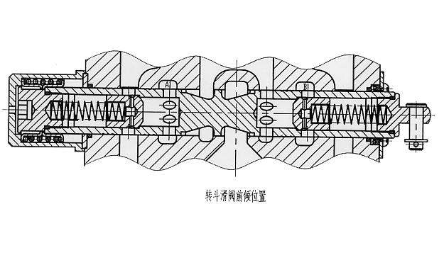
Move the tilt valve spool rightward (See Figure3-17) to close the chamber T and P1. The hydraulic oil will flow to port “c” via chamber P to open the check valve, and then flow to the rear chamber via port A1 to make the bucket roll back. The hydraulic oil in the front chamber will flow to port “d” via port B1 to open the check valve and flow back to oil tank.
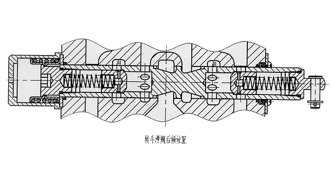
Figure 3-17 Bucket roll back
Bucket dump
Move the tilt valve spool leftward (See Figure3-18) to close the chamber T and P1. The hydraulic oil will flow to port “d” via chamber P to open the check valve and flow to the front chamber via port B1 to make the bucket dump. The hydraulic oil in the rear chamber will flow to port “c” via port A 1 to open the check valve and flow back to oil tank.
When the external force for moving the spool is released, the valve spool will be returned by the spring force to the middle (hold) position.