Figure 2-7
3.7.2.5 Bulldozing
3.7.2.5.1 Level the bucket on the ground.
3.7.2.5.2 Depress the throttle pedal to move forward. When you feel hard to move further, slightly raise the lift arm so as to continue moving. When lifting or lowering the lift arm, the lift control lever should be moved between the positions Raise and Lower without staying in a fixed position so as to ensure smooth bulldozing. See Figure 2-8.
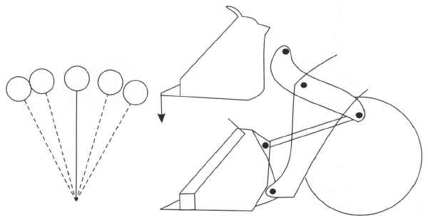
Figure 2-8
3.7.2.6 Scraping
3.7.2.6.1 Bucket is turned to its limit to make the cutting edge contact with ground.
3.7.2.6.2 For hard road, the lift control lever should be put in floating position. For soft road, it should be placed in neutral position.
3.7.2.6.3 Move at Reverse speed to scrape the ground.
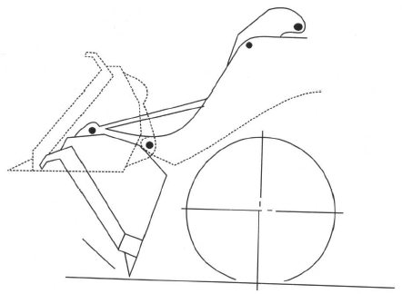
Figure 2-9
3.7.2.7 Towing
3.7.2.7.1 Firmly link the towed vehicle with the coupling pin of wheel loader.
3.7.2.7.2 Hold the implement at the carrying position.
3.7.2.7.3 The travel should be started and stopped gently. Make sure the brake system can work normally before going downhill. Reliable brake system must be installed on the towed vehicle for ensuring safety.
3.7.2.8 Craning
You can perform craning with appropriate slinging tool.
4. Lubrication
Proper lubrication can greatly reduce friction and abrasion, ensure normal operation and prolong the work life of the machine.
4.1 Precaution for filling oil/grease:
4.1.1 Clean the oiling container and oiling ports. Replace the damaged grease nozzle.
4.1.2 The machine should be leveled when checking oil level.
4.1.3 When oiling front/rear axles, fill the oil through the oiling port on the left/right hub until the oil is overflowed from the overflow plug of the axle housing.
4.1.4 Refer to the check plug when oiling the transmission. The oil level should be between the upper and lower limits. When filling oil into the hydraulic tank, the oil level should be between the upper and lower observation ports. Run the engine for 5 minutes and check the oil level before first time of oiling.
4.2 Type of lubricant (see Table 2-1)
4.3 Fill oil and grease
4.3.1 Engine oil
It is for the lubricating system of engine.
The reticle “Static full” stands for the required oil level before engine is started; “Active full” stands for the required oil level for engine running; and “Danger” means that oil must be refilled immediately.
4.3.2 Oil in torque converter and transmission
Fill the oil through the oiling port of transmission until the oil can be out from the upper drain plug. After engine runs, the oil level should not be lower than the drain plug. The oil is used to transfer torque and lubricate the parts.
4.3.3 Oil in axle
Fill the oil through the oiling port at left/right hub until the oil can be overflowed through the overflow port at the middle of axle housing when the plug is taken off. The oil is used for lubricating the final drive and wheel speed reducer.
4.3.4 Oil in hydraulic steering system and implement hydraulic system
Fill the oil through the port on the top of the oil tank until the oil level is between the upper and lower observation ports on the oil tank. The oil will be pumped for supplying the hydraulic system.
4.3.5 Grease
The grease refilling point is usually located at each sliding bearings/rolling bearings such as:
4.3.5.1 Bearings on engine coolant pump and fan;
4.3.5.2 Bearings on spider of drive shaft;
4.3.5.3 Pins/bushes at both ends of cylinder;
4.3.5.4 Pins/bushes on hitch of front and rear frames, and on oscillating suspension;
4.3.5.5 Each pin/bush in the implement.
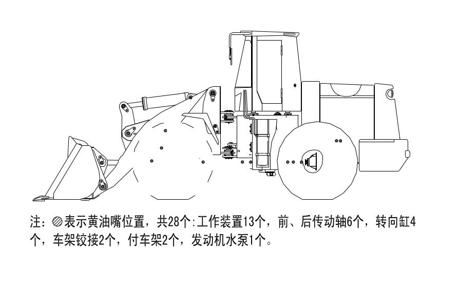
Note:
“●”
stands for grease fitting location. There are totally 28 fittings,
13 of them are on implement, 6 on front/intermediate/rear drive
shafts, 4 on steering cylinder, 2 on hitch, 2 on oscillating
suspension and 1 on engine coolant pump.