8. Brake system
8.1 General description
The brake system is used to speed down or stop, or to park on the flat or sloped ground.
The brake system includes service brake and parking brake.
8.2 Service brake system
Service brake system is used to regulate the speed or stop the vehicle. The brake is disc type and is manipulated by foot pedal. So it is also called “foot brake”. The brake torque is equally divided to front and rear wheels. The brake for front wheels is the same as that for rear wheels. Booster pumps are quipped. This service brake system provides reliable and smooth braking. It is easily accessible for maintenance.
8.2.1 Main structure and working principle of service brake system:
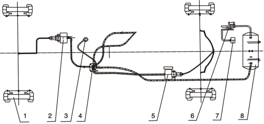
Figure 3-25 Brake system
1. Disc brake 2. Front booster pump 3. Air pressure gauge 4. Air valve
5. Rear booster pump 6. Relief valve 7. Air compressor 8. Air tank
Refer to Figure 3-25. The engine drives the air compressor (7). The compressed air is delivered to the air tank (8) through the relief valve (6). The system pressure is 0.784Mpa. There are two outlets in the air tank. One is connected to the inlet of air brake valve (4), the other is connected with a valve for inflating the tire or cleaning the air cleaner element of diesel engine.
When the pedal of air brake valve (4) is depressed, the compressed air from the air tank gets into the front booster pump (2) & rear booster pump (5) via air brake valve. After boosted by the booster pump, the hydraulic oil pushes the piston of disc brake (1) so that the brake pads are pressed to the disc (the pressure is about 9.8MPa) to realize braking. When the pedal of air brake valve is released, the compressed air from the front and rear booster pump is exhausted and the brake is not applied.
8.2.2 Main parts in service brake system:
Service brake system consists of air compressor, relief valve, air tank, air brake valve, front/rear booster pump, disc brake, etc.
A. Air compressor:
It is air-cooled and piston type with two cylinders. It is supplied with engine and installed in front of fuel pump. It is driven by the timing gear. Engine supplies oil to it for lubrication. It is cooled by air. Its air intake pipe is connected with the air pipe of engine. The oil from engine is metered by orifice and gets to the oil pan of air compressor. The oil keeps in certain level. The surplus oil returns to the engine via oil pipe.
When the compressed air is not used, the air compressor will still work for dozens of minutes. When the air compressor works normally, the air pressure in the brake system will keep constant. If the air pressure drops rapidly or fluctuates, check the air bleed valve of air compressor. Lapping may be needed to ensure the airtightness.
Large amount of oil is not allowed to get into the compressed air when the air compressor is running. If the oil accumulated in the relief valve is more than 10-15cm3 after 24-hour operation, check and find out the cause. Replace the piston ring if it is worn.
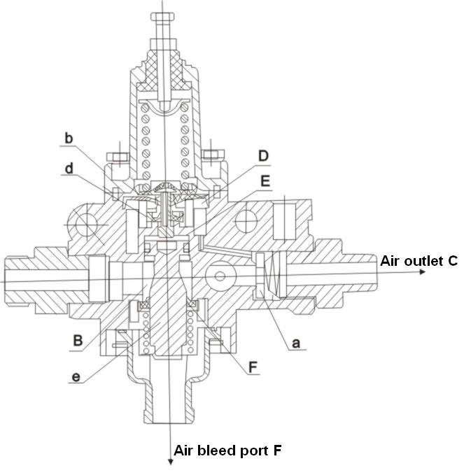
B. Relief valve
It is used to regulate the pressure in the air brake system and automatically drain the oil, water and dirt screened. It can also be used to inflate the tire when a special connector is attached.