

Micro-Cap v7.1.6 / RM
.PDFtext are increased by one. If no numerals are present, a '1' is added to the text.
•Node Snap: This flag compels components, wires, and text to originate on a node if a node's pin connection dot is within one grid of the object being placed or moved.
•Auto Show Model: This mode causes model statements added to the schematic text area to automatically split the circuit window and show the newly added model statement.
•Component Cursor: If enabled, this option replaces the mouse arrow with the shape of the currently selected component whenever Component mode is active. This has the advantage of showing the currently selected component and its size.
•Rubberbanding: If enabled, this option causes drag operations to extend the circuit wires to maintain node connections. When disabled, drag operations sever selected wires at their endpoints and drag them without changing their shape or length.
SHIFT + CTRL + R toggles the feature on and off to allow the rapid mode switches, necessary when dressing up a schematic.
•Show Slider: If enabled, this option places a slider control on the schematic adjacent to batteries and resistors during Dynamic DC Analysis. This lets the user change the battery or resistor values by dragging the slider with the mouse. With or without the slider, the values can be changed by regular amounts with each press of an UP ARROW or DOWN ARROW cursor key.
•Nodes Recalculation Threshold: If the Show Node Numbers option is enabled, nodes are recalculated and displayed whenever any schematic editing is done. For large schematics this can be time consuming. This value sets an upper limit for node count beyond which automatic node recalculation will be ignored, even if the Show Node Numbers option is enabled.
•Block Select Display Mode: This option enables the block select mode, which shows the background of selected objects in the Block Select color. This makes the selected objects easier to spot, especially when there is only one object. If disabled, the selected object is drawn in the standard foreground Select color.
67
•Automatically Add Opamp Power Supplies: This option automatically adds and connects the VCC and VEE power supplies for level 3 opamp primitives. It places the batteries on a schematic page called Power Supplies. Note that it will not work for vendor-generated opamp subckt models.
•Color Palettes: This option lets you define your own palettes. Click on any of the color squares to invoke a color editor that lets you customize the hue, saturation, and luminance of the selected palette color.
•Format: This option controls the numeric format to be used when displaying analysis plot tag values, DC operating point values in the numeric output text page, schematic node voltages, currents, and powers, schematic path delays, and formula text.
•Status Bar: This lets you change the Status bar text attributes.
•Main Tool Bar: This panel lets you show or hide buttons and tool bars that normally reside in the main tool bar area.
•Component Palettes: This lets you name the nine component palettes and control their display in the Main tool bar. You can also toggle their display on and off during schematic use with CTRL + palette number.
•Auto Save: This accesses the Auto Save dialog box from which you can enable automatic saving of circuit files to disk every time you run an analysis or on a specific time schedule.
•Warnings: This accesses the Warnings dialog box from which you can enable specific warning messages including:
•File Warning: This provides a warning when closing an edited file whose changes have not yet been saved.
•Quit Warning: This asks if you really want to quit.
•Opamp Power Supplies: This alerts the user when MC7 adds VCC and VEE power supplies.
•Add DC path to ground: This warns when adding resistors to avoid a DC path to ground.
68 Chapter 2: The Circuit Editor
• Default Properties For New Circuits: This dialog box controls the properties of new circuits. It includes:
•Schematics: This controls three types of features for schematics:
•Color/Font: This provides control of text font and color for various schematic features such as component color, attribute color and font, and background color.
•Title Block: This panel lets you specify the existence and content of the title block.
•Tool Bar: This panel lets you select the tool bars and buttons that will appear in the local tool bar area located just below the main tool bar.
•SPICE Files: This provides two types of features for SPICE text files.
•Color/Font: This provides control of text font and color for SPICE text files.
•Tool Bar: This panel lets you select the tool bars and buttons that will appear in the local tool bar area located just below the main tool bar.
•Analysis Plots: This provides control for several analysis plot features:
•Scales and Formats: This panel lets you specify the numeric format for the Numeric Output, plot scales, Cursor mode tables, Optimizer values, and Watch values. It allows selection of Same Y Scales for separate plot groups and lets you select the method for measuring slope: normal, dB/octave, and dB/decade. The latter two are more appropriate to certain AC measurements.
•Colors, Fonts, and Lines: This provides control of text font and color for various plot features such as general scale and title text, window and graph background colors, and individual curve color, thickness, and pattern.
•Tool Bar: This panel lets you select the tool bars and buttons that will appear in the local tool bar area located just below the main tool bar.
69
•3D Plots: This provides control for several 3D plot features:
•Color: This provides color control of 3D plot features such as general scale and title text, window and graph background colors, axis colors, patch color, and surface line color.
•Font: This provides font control for all text in the 3D plot.
•Scales and Formats: This panel lets you select the numeric format for the X, Y, and Z axis scales and the numeric values in the cursor tables. It also controls the slope calculation method.
•Tool Bar: This panel lets you select the tool bars and buttons that will appear in the local tool bar area located just below the main tool bar.
•Monte Carlo Histograms: This provides control for Monte Carlo histogram plot features:
•Color: This provides color control of histogram features such as general scale and title text, window and graph background colors, and bar colors.
•Font: This provides font control for all text in the histogram.
•Tool Bar: This panel lets you select the tool bars and buttons that will appear in the local tool bar area located just below the main tool bar.
•Performance Plots: This panel controls performance plot features:
•Scales and Formats: This panel lets you select the numeric format for plot scales and values shown in the Cursor tables. It also allows selection of same Y scales for separate plot groups.
•Colors, Fonts, and Lines: This provides control of text font and color for various plot features such as general scale and title text, window and graph background colors, and individual plot color, thickness, and pattern.
70 Chapter 2: The Circuit Editor

• Tool Bar: This panel lets you select the tool bars and buttons that will appear in the local tool bar area located just below the main tool bar.
•Global Settings: (CTRL + SHIFT + G) This accesses the Global Settings dialog box where many simulation control choices are made. These settings are discussed in greater detail in the Global Settings section of the Circuit editor chapter of the Reference Manual.
•User Definitions: This option displays the file MCAP.INC. This file, located on the directory with MC7.EXE, stores global definitions for use in all circuits. The contents of the file are automatically included in all circuit files.
•Model Parameter Limits Editor: This editor lets you set the minimum and maximum values that the model parameters can have. It also shows the default values, but does not allow you to edit them. A warning message is generated and placed in the numeric output file for parameters that do not fall within the limit values. You can also run a comprehensive check of all models from Windows / Check Model Library Parameters.
•Component Palettes: This option accesses the Component Palettes. These provide a quick and convenient alternative to the Component menu when choosing components for placement in the schematic. Membership in a palette is specified from the Component editor. The original disks provide several sample palettes containing common analog and digital components. The palettes can be tailored to suit personal preferences. Palette display can be toggled on and off by pressing CTRL + palette number. For example, CTRL + 1 toggles the display of palette 1.
.
71

The Analysis menu
The Analysis menu is used to select the type of analysis to run on the circuit in the active window. It provides six basic options:
•Transient: (ALT + 1) This option selects transient analysis. This lets you plot time-domain waveforms similar to what you'd see on an oscilloscope.
•AC: (ALT + 2) This option selects AC analysis. This lets you plot frequency-domain curves similar to what you'd see on a spectrum analyzer.
•DC: (ALT + 3) This option selects DC sweep analysis. This lets you plot DC transfer curves similar to what you'd see on a curve tracer.
•Dynamic DC: (ALT + 4) This option selects an analysis mode in which MC7 automatically responds to user edits by finding and displaying the DC solution to the current schematic. You can change battery voltages and resistor values with slider controls or with the cursor keys. You can also make any edit such as adding or removing components, editing parameter values, etc. MC7 responds by calculating the DC solution and will display
voltages and states if  is enabled, currents if
  is enabled, power dissipation if
  is enabled, and device conditions if
  is enabled.
•Transfer Function: (ALT + 5)This option selects an analysis mode in which the program calculates the small signal DC transfer function. This is a measure of the incremental change in a user-specified output expression, divided by a very small change in a user-specified input source value. The program also calculates the input and output DC resistances.
•Sensitivity: (ALT + 6) This option selects an analysis mode in which the program calculates the DC sensitivity of one or more output expressions to one or more input parameter values. The input parameters available for measurement include all those available for component stepping, which is practically all model parameters, all value parameters, and all symbolic parameters. Thus you can create a lot of data with this analysis. A suitably smaller set of parameters is specified in the default set, or you can select only one parameter at a time.
72 Chapter 2: The Circuit Editor
•Probe Transient: (CTRL + ALT + 1)This selects transient analysis Probe mode. In Probe mode, the transient analysis is run and the results are
stored on disk. When you probe or click part of the schematic, the waveform for the node you clicked on comes up. You can plot all of the variable types, from analog node voltages to digital states. You can even plot expressions involvingcircuitvariables.
•Probe AC: (CTRL + ALT + 2) This option selects AC Probe mode.
•Probe DC: (CTRL + ALT + 3) This option selects DC Probe mode.
73
The Design menu
The Design menu accesses the Filter Design functions.
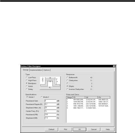
• Active Filters: This part of the program designs an active filter from your filter specifications. The filter type can be low pass, high pass, band pass, notch, or delay. The filter response can be Butterworth, Chebyshev, Bessel, elliptic, or inverse-Chebyshev. Polynomials are calculated from the filter specifications, then mapped into one of several different circuit styles, ranging from classical Sallen-Key to Tow-Thomas. Optional plots of the idealized transfer function are available. Filters can be created as circuits or as macro components.
Figure 2-12 The Active Filter Designer
• Passive Filters: This part of the program designs a passive filter from your specifications using capacitors and inductors. The filter type can be low pass, high pass, band pass, or notch. The filter response can be Butterworth or Chebyshev. The filter polynomials are calculated and implemented in either standard or dual circuit configuration. Optional plots of the idealized transfer function are available. Filters can be created as circuits or as macro components.
The filter design functions from the Design menu is covered in more detail in Chapter 12.
74 Chapter 2: The Circuit Editor
The Model editor
Model libraries provided with MC7 come in two forms, text and binary.
In text form, they are contained in files with the extension LIB, and encode device models as .MODEL, .MACRO, and .SUBCKT statements. Text files can be viewed and edited with any text editor, including the MC7 text editor.
In binary form, model libraries are contained in files with the extension LBR, and are implemented as a list of model parameters for the parts. These binary files can be viewed and edited only with the Model editor. The Model editor is invoked when the File menu is used to open or create a binary library file.
The Model editor should not be confused with the MODEL program, which is accessed from the Windows menu. MODEL is a separate Windows program which produces optimized analog model parameters from commercial data sheets. MODEL can create model libraries in either the text or binary form.
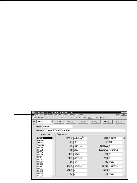
Once the binary libraries are created, the Model editor can be used to view and edit them. The Model editor display looks like this:
File menu
Type selector
Part name
Part selector
Model display
Figure 2-13 The Model editor
75
The various parts of the editor function as follows:
•Name: This field is where the part name is entered. If the part has been imported from the MODEL program, this field is a copy of the T1 text field.
•Memo: This is a simple text field that may be used for any descriptive purpose. If the part has been imported from the MODEL program, this field is a copy of the T3 text field.
•Type selector: This is used to select which device type to display. Each library may contain a mixture of different device types. Selecting NPN for example, displays all of the NPN bipolar transistors in the file.
•Part selector: This selects a part by name for display and possible editing. It provides a window to review the specific model values for the displayed part. As in other windows, the Maximize button may be used to enlarge the window to see more of the model values.
•Add: This adds a new part of the current device type to the current library.
•Delete: This deletes the displayed part.
•Pack: This removes all duplicated and untitled parts and reorders the parts alphanumerically.
•Copy: This command copies a part from the displayed library to a target library. If the target library already has a part with the same name, the name of the newly created copy is set to "oldname_copy". The target library may be the current library.
•Merge: This command merges a library from disk with the library currently in memory. The merged library is displayed but is not automatically saved to disk.
•Go To: This command lets you specify a parameter name, then scrolls the parameter list of the currently displayed part to show the parameter value.
Note that the Find function is available to locate parts by name in the current library file or in one of the library files on disk. Simply click on the Find
button  in the Tool bar.
76 Chapter 2: The Circuit Editor