

Micro-Cap v7.1.6 / RM
.PDFDialog boxes
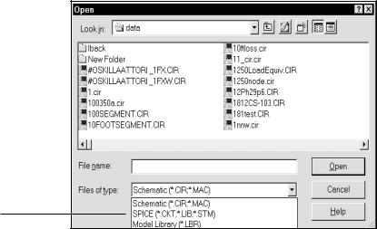
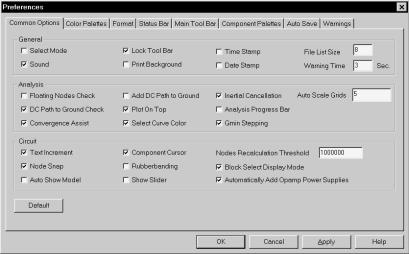
Dialog boxes are used to request information about a task you are performing or to provide information you might need. An ellipsis after a menu item means a dialog box will appear when you choose that item. For example, choosing the Open item from the File menu invokes the File Open dialog box. It looks like this:
Listbox |
|
|
|
|
|
|
Open button |
|
|
|
|
|
|||||
Text box |
|
|
|
|
|
|
||
|
|
|
|
|
|
|||
|
|
|
|
|
|
Cancel button |
||
Drop-down list box |
|
|
|
|
||||
|
|
|
|
|
||||
|
|
|
||||||
Figure 1-2 The File Open dialog box
This particular dialog box lets you choose a file to open. It also lets you choose the drive, directory, and selectively display available file names.
Dialog boxes let you choose different program features and control the program's behavior. Choices are made using several types of controls, including command buttons, text boxes, list boxes, drop-down list boxes, option buttons, and check boxes.
Dialog box option types:
Command buttons
You choose a command button to initiate immediate action, such as executing or canceling a command. The OK and Cancel buttons shown in Figure 1-2 are typical command buttons.
7
Text boxes
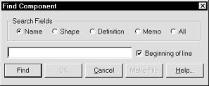
A text box is used to enter text information such as the name of a file, analysis run time, or an algebraic formula. For example, here is the text box used by the Find command.
Figure 1-3 The Find text box
When the text box appears, old text is selected and any typing replaces the old text. You can also delete selected text by pressing the Delete key. If no old text exists the text cursor is placed at the left of the text field.
To select text in a text box:
Mouse
Drag the text cursor across the text to be selected. To select a single word, double-click on it.
Keyboard
1.Use the cursor arrow keys to move to the left of the first character you want to select.
2.To extend the selection, hold the SHIFT key down while pressing either the left or right arrow key. Press SHIFT + END to extend the selection to the last character in the field.
List boxes
A list box displays a list of choices. If there are more choices than can fit in the box, scroll bars appear that let you browse the remainder of the list.
Normally, you select only one item from a list box, but some list boxes let you select more.
8 Chapter 1: Windows Basics
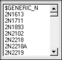
Figure 1-4 A typical list box
To select a single item from a list box:
Mouse
Click on the scroll arrows until the item you want is displayed. Click on the item you want to select. Double-click on the item to both select and choose it in a single step.
Keyboard
Use the arrow keys to scroll to the desired item or type the first letter of the item. Press ENTER to choose the selected item.
To select multiple contiguous items from a list box:
Mouse
Click on the first item. Then press the SHIFT key down and click on the last item. This selects all of the items between the first and the last, inclusive. To cancel the selection, click on any item in the list with the SHIFT key up.
Keyboard
Use the arrow keys to scroll to the desired item or type the first letter of the item. Press and hold the SHIFT key. Press the UP or DOWN ARROW keys until the items you want are selected. To cancel the selections, release the SHIFT key, and press either the UP or DOWN ARROW key.
To select multiple noncontiguous items from a list box:
Mouse
This procedure can only be done with the mouse. Press and hold CTRL and click on each item you want to select. To cancel a selection, press and hold CTRL and click on the selection you want to cancel.
9
Drop-down list boxes
Drop-down list boxes appear initially as a rectangular box with the current selection marked. When you select the arrow in the square box at the right, a list of alternative choices drops down. If the list is too big for the box, scroll bars appear that let you browse the list.
Drop-down list box
Figure 1-5 A drop-down list box
To open a drop-down list box and select an item:
Mouse
1.Click the arrow in the square box at the right to open the box.
2.Click the up or down scroll arrow, or drag the scroll box until the item you want to select is visible.
3.Click the item.
Keyboard
1.Press ALT + DOWN ARROW to open the box.
2.Press the UP or DOWN ARROW key to select the desired item.
3.Press ALT + UP ARROW or ALT + DOWN ARROW to choose it.
10 Chapter 1: Windows Basics
Option buttons
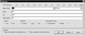
Option buttons are used when you must choose between mutually exclusive options. The selected item button contains a black dot. Items which are not available are dimmed. In the dialog box below, the Method option is chosen from the mutually exclusive group containing Linear, Log, and List.
Figure 1-6 Option buttons
To select an option button:
Mouse
Click the option button.
Keyboard
1.Press TAB to move to the desired option group.
2.Use the UP or DOWN ARROW keys to select the desired button.
If the option has an underlined letter, you can select the option button by typing ALT + the underlined letter. This selects the option. Actually choosing the selected option occurs when you exit the dialog box by choosing the OK button.
11
Check boxes
A check box adjacent to an option means you can select or clear the option. If the box contains an X the option is selected, or in effect. If the box is empty the option is clear, or not in effect. When you select the option you toggle its state between selected and clear. The names of unavailable options are dimmed.
Figure 1-7 Check boxes
To select or deselect a check box:
Mouse
Click each blank check box that you want to select. Click each selected box that you want to clear.
Keyboard
1.Press TAB to move to the desired check box group.
2.Press the SPACEBAR to select the box.
3.Press the SPACEBAR again to clear the selection.
If the option has an underlined letter, you can select or clear the option by typing ALT + the underlined letter.
12 Chapter 1: Windows Basics

Chapter 2 The Circuit Editor
What's in this chapter
This chapter describes the Circuit editor, the foundation of the Micro-Cap 7 user interface. The Circuit editor provides access to all of the basic program functions, including circuit construction, analyses, and the various editors.
Features new in Micro-Cap 7
•Portable schematic files save shape, component, and model data.
•User-specified paths (folders) for circuit and model library files.
•Edit and plot within the Attribute dialog box.
•Multistage Undo and Redo commands.
•Improved Component Find command.
•Status bar shows digital expressions, current, and power at mouse location.
•Formula text.
•Smooth one-pixel schematic panning.
•Bill of materials.
•PADS PCB output.
•Model parameter range checker.
•Multiple file opener opens many files at once.
•CTRL+delete cuts wires at box boundary.
•Automatic file saver.
•Expandable component palettes.
•JPG, BMP, and GIF picture files.
13

Circuit structure
MC7 analyzes circuits. A circuit is an interconnection of electrical components. There are two basic types of circuit description that MC7 uses:
•Schematic, a picture of the circuit topology.
•SPICE text file, a textual description of the circuit topology.
Schematics
Schematics are comprised of drawings and text. Drawings provide the circuit description and text provides the modeling and analysis information required for an AC, DC, or transient analysis. MC7 runs analyses from data contained in the schematic. It is not necessary to convert it to a SPICE netlist first, although MC7 can also analyze SPICE netlists. Sometimes MC7 also uses modeling information from libraries referenced in the schematic.
Each schematic contains a drawing area and a text area.
Drawing area
The drawing area contains one or more pages of analog and/or digital components interconnected by wires. It may also contain graphical objects (which contain no electrical information) and grid text (which may contain electrical information). Grid text can be moved from the drawing area to the text area and vice-versa by selecting it and pressing CTRL + B. This is called the shuttle command. Pages can be added or deleted from the Edit menu or with a right click on any page tab in the page selector at the bottom of the schematic window. Page display is controlled by the page scroll bar located at the lower left part of the circuit window.
Text area
The text area contains only text. It can hold local command statements, subcircuit descriptions, model statements, and digital stimulus statements that may be too bulky for convenient display in the drawing area. There is only one page, but it can be as long as you like. The editor is capable of handling multi-megabyte text files.
The display can be toggled between the text area and the current schematic page by pressing CTRL + G. The text area can be selected by clicking on the text area tab in the page scroll bar area. To return to the schematic, click on one of the desired page tabs or press CTRL + G.
14 Chapter 2: The Circuit Editor
You can split the display to simultaneously show different parts of the drawing and/or text areas by dragging the vertical or horizontal splitter bar towards the middle of the window.
SPICE text files
SPICE text files are standard SPICE text descriptions of a circuit, a subcircuit, or a model statement. MC7 generally follows the original Berkeley SPICE2G format, with many PSpiceTM, SPICE3, and even a few HSPICE extensions. Text files are entered and edited in a text document similar to what a text editor or a word processor creates. When you create a new SPICE text file, MC7 opens a text document and lets you edit it as desired. Only when you start an analysis does MC7 error check it.
Note that MC7 can also translate schematics into SPICE text files of various flavors, in case you want to check the accuracy of an external SPICE simulator against MC7. MC7 will, of course, accept such files for analysis.
15

Schematic objects
Object, in the context used here, is a general term for anything that can be placed in a schematic. There are several types of objects:
•Components: This includes all analog and digital sources, active and passive parts, and connectors. In short, it includes any object chosen from the Component menu.
•Wires: Wires are used to interconnect components. There are two types of wires: orthogonal and diagonal. Orthogonal wires are restricted to the vertical or horizontal direction. They may contain both a vertical and a horizontal segment. Diagonal wires are drawn at any angle and only contain one segment.
•Text: Text, sometimes referred to as grid text because its origin is restricted to an imaginary grid, is used for naming nodes, creating command statements, and general documentation.
•Graphics: Graphical objects include lines, rectangles, ellipses, diamonds, arcs, pies, and pictures. They are used for aesthetic or documentation purposes and have no effect on the electrical behavior of the circuit.
Schematics may contain picture files in any of the following formats: WMF, EMF, JPG, BMP, and GIF. The most common use of this feature is to place a picture of an analysis plot in a schematic. Picture files of any MC7 window with graphics may be captured by the Copy The Entire Window to a Picture File command on the Edit menu. Once the picture file has been created, it can be included in a schematic as a graphic object.
• Flags: Flags mark locations in a schematic that you are likely to want to view many times. They facilitate rapid switching of the display between multiple circuit locations. They are most useful in very large circuits, where the display redraw time may be too long for convenient use of the scroll bars.
These are the only objects that can be placed in a schematic.
Note that grid text is the only object that can be shuttled between the drawing and text areas.
16 Chapter 2: The Circuit Editor