

Micro-Cap v7.1.6 / RM
.PDFSchematic modes
The Schematic editor is a modal editor. That means the behavior of the mouse when it is clicked or dragged in the schematic depends upon what mode it is in. Schematic modes affect either the mouse behavior or the schematic display.
•Behavioral modes
•Circuit altering modes
•Select mode
•Component mode
•Text mode
•Wire mode
•Diagonal wire mode
•Graphics / Picture File mode
•Flag mode
•Circuit querying modes
•Info mode
•Help mode
•Point to end paths mode
•Point to point paths mode
•View modes
•Attribute Text
•Grid Text
•Node Numbers
•Node Voltages / States
•Current
•Power
•Condition
•Pin Connections
•Grid
•Cross-hair Cursor
•Border
•Title
The behavioral modes are mutually exclusive. At any given moment, only one mode is active. You can tell which mode is active by looking at the mode buttons. An active mode button is pushed in. An inactive mode button is pushed out.
17

To select a mode click its button. This deselects the prior mode button.
Behavioral modes:
Select mode: This selects an object, region, or location for one of several actions:
•Editing the selected object (Requires a double click)
•Clearing the selected region (Deleting without copying to the clipboard)
•Cutting the selected region (Deleting with copying to the clipboard)
•Moving the selected region
•Rotating the selected region
•Stepping the selected region
•Mirroring the selected region
•Making a macro of the selected region
•Copying the selected region to the clipboard
•Making a BMP file of the selected region
•Drag copying the selected region
•Moving the selected object to front or back
•Shuttling the selected text object between the text and drawing areas
•Changing the selected object's color or font
•Defining the upper-left corner position of a subsequent paste operation To select an object you must first be in Select mode. To enter Select mode:
•Click on the Select mode button  or press CTRL + E.
•Press the SPACEBAR key. Press it again to restore the original mode.
•Press and hold the SHIFT or CTRL key down. In this mode you can select an object or a region, but you can't drag the mouse. When the key is released, the original mode is restored.
To select a contiguous group of objects, drag the mouse over the region containing the objects. To select a noncontiguous group of objects, hold down the SHIFT button and click the mouse on each object.
Component mode: This mode lets you add components to the schematic. The component that gets added is the last one chosen.
Text mode: This mode lets you add grid text to the schematic. Grid text is used for node naming, defining electrical characteristics, and documentation.
Wire mode: This mode lets you add orthogonal wires to the schematic. Orthogonal wires can have one or two segments and be vertical or horizontal or both.
18 Chapter 2: The Circuit Editor

Diagonal wire mode: This mode lets you add diagonal wires to the schematic.
Graphics/Picture File mode: This mode lets you add a graphical object (line, rectangle, ellipse, pie, arc, diamond, or picture file) to a circuit. Picture files are typically created with the Edit / Copy The Entire Window to a Picture File command.
Flag mode: This mode lets you add flag markers for rapid navigation of large schematics with many pages.
Info mode: This mode provides model information about a part when you click on it. The information is usually a model, subckt, or define command statement for the part. If the part is a macro, the macro circuit which it represents is displayed. If it is a subckt, the subcircuit description is displayed. If it is a device that uses a model statement, the model statement is displayed. Double-clicking on the part also displays model information in the Attribute dialog box.
Help mode: In this mode, you click on a component to display its parameter or attribute syntax. ALT + F1 gives syntax help on selected SPICE part names.
Point to End Paths: In this mode, you click on a digital component and MC7 traces all of the digital paths that originate at the component and end when they drive no other combinatorial component.
Point to Point Paths: In this mode, you click on two successive digital components and have MC7 trace all of the digital paths between the two components.
View modes:
Attribute text mode: This mode controls the display of all attribute text. Attribute text will be displayed only if the individual attribute display check boxes are enabled and the Attribute text mode is enabled.
Grid text mode: This mode controls the display of all grid text. If disabled, all grid text is invisible. If enabled, all grid text is visible except command text, which is visible only if this button and the command text button are both enabled.
Node numbers: This mode displays the numbers assigned by MC7 and used to identify circuit nodes.
Node Voltages / States: This mode displays time-domain values of node voltages for analog nodes and node states for digital nodes.
19

Current: This mode shows the last time-domain currents for each component. Currents are shown with an arrow indicating the direction of positive current.
Power: This mode displays the last time-domain values of stored, generated, and dissipated power for each component.
Condition: This mode displays the last time-domain condition for each component which has conditions. Typical conditions for a BJT are LIN (linear), SAT (saturated), OFF (both junctions off), and HOT (excessive power dissipation).
Pin connections: This mode marks pin locations with a dot. These are the places where connections are made to wires or other component pins.
Grid: This mode displays the schematic grid to which objects are anchored. All wires, components, and other objects originate on a grid.
Cross-hair cursor: This mode adds a full-screen schematic cross-hair cursor. Its principle use is in aligning components.
Border: This mode adds a border around each printed sheet of the schematic.
Title: This mode adds a title block to the corner of each schematic sheet. There is an option to have only one title block per page. This option is accessible from the Properties dialog box, accessed with F10.
20 Chapter 2: The Circuit Editor
Circuit editor
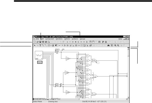
The Circuit editor creates and edit circuits. When the circuit is a schematic, it becomes the Schematic editor and its display looks like the figure below:
Menus |
|
Title bar |
|
Vertical splitter
Main tool bar Circuit toolbar
|
|
|
|
|
|
|
|
|
|
|
|
|
|
Vertical scroll |
|
|
|
|
|
|
|
|
|
|
|
|
|
|
|
bar controls |
|
Page selector tabs |
|
|
|
|
|
|
|
|
|
|
|
||||
Page scroll bar controls |
|
|
|
|
|
|
|
|
|
|
|
||||
|
|
|
|
|
|
|
|
|
|
|
|
||||
Horizontal splitter |
|
|
|
|
|
|
|
|
|
|
|
|
|
||
|
|
|
|
|
|
|
|
|
|
|
|
|
|||
|
|
|
|
|
|
|
|||||||||
|
|
|
|
|
|
|
|
|
|
|
|
|
|
|
|
|
|
|
|
|
|
|
|
|
|
|
|
|
|
|
|
|
|
|
|
|
|
|
|
|
|
|
|
|
|
|
|
|
|
|
Selected page |
|
Horizontal scroll bar |
control |
|||||||||
|
|
Page tab display width control |
|
Status bar (showing component information) |
|||||||||||
|
|
|
|||||||||||||
Figure 2-1 The Schematic editor
The principal components of the editor are as follows:
Menus: Located beneath the title bar, menus select major functional groups.
Title bar: Located in the top center of the window, the title bar displays the name of the window. The mouse can be used to move the window by dragging the title bar.
Main tool bar: Shown below the title bar, the main tool bar contains buttons that represent the most frequently used options, such as file operations and access to the various editors. The tool bar provides a quick way to access those options.
Clicking on a button will activate the desired option.
Circuit tool bar: Shown below the main tool bar, the circuit tool bar contains buttons that represent the most frequently used menu options that apply specifi-
21
cally to the circuit. The tool bar provides a quick way to access those options. Clicking on a button will activate the desired option.
Schematic scroll bars: These scroll bars, located to the right and the bottom of the window, let you pan the schematic vertically or horizontally. Clicking on the scroll arrows pans the display roughly 10% of the window width per mouse click. Moving the scroll box, either by dragging it or by clicking in the scroll bar area, moves the view to a location proportionate to the new scroll box position relative to the scroll bar end points.
Page selector tabs: Located in the lower left of the window, the page selector tabs let you select a particular page for viewing.
Selected page: The color of the selected schematic page tab is the window background color.
Text area tab: The text area is selected by clicking on the Text tab. CTRL + G may also be used.
Splitter bars: Dragging these bars across the window splits it into two parts, with a vertical or horizontal bar between. Each part can be independently scrolled and toggled between text and drawing areas. Only one split section at a time can display the text area. Each split section can be scrolled or panned to view different parts of the schematic.
Status bar: This bar describes the items the mouse pointer is currently passing over. It is also used to print informative messages.
When the mouse is over a part, the center pane will show its Component library memo field if it has any descriptive text.
The pane at the right shows the part type and information about its last current and power values.
If the part is a digital primitive gate, it will print the logic expression.
22 Chapter 2: The Circuit Editor

Selecting and deselecting objects
To manipulate an object after it has been placed in the schematic, it must first be selected. Selection or de-selection requires the use of the mouse and follows the general Windows rules.
First step: If not already in Select mode, click on the Select mode button  in
in
the Tool bar or press CTRL + E. You can also toggle between Select mode and the current mode using the SPACEBAR key.
Second step:
To select a single object:
Click on the object. The object is selected.
To select or deselect a single object:
Press SHIFT and click on the object. The object's selection state is toggled. If the object was formerly selected, it becomes deselected. If it was formerly deselected, it becomes selected.
To select multiple contiguous objects:
Drag the mouse creating a region box. This selects all objects that originate within the box.
To select or deselect multiple contiguous objects:
Press SHIFT and drag the mouse creating a region box. This toggles the selection state of all objects originating within the box.
To select or deselect multiple noncontiguous objects:
Press and hold SHIFT while clicking on each individual object or dragging on each group whose selection status you want to change. This toggles the selection state of the object or group.
When would you want to deselect specific objects? Sometimes it is necessary to select most but not all of a large group of contiguous objects. It is easier and faster to drag select the entire group and then deselect one or two of them than to individually select each of the desired objects.
If you click on a component's attribute text, the text will be selected, not the component. Be careful to click within the component where there is no attribute text. Single-clicking on attribute text selects it and lets you move it. Double-clicking on
23
attribute text opens a local edit box at the text location and lets you edit it there without using the Attribute dialog box.
To select all objects in the window, press CTRL + A. To deselect all objects, click on any empty space in the window.
Rapid switching to/from Select mode:
In the course of building or editing a schematic, it often happens that you need to rapidly switch between modes, especially between Select mode and Component or Wire mode. To make this process easier several short term mode switchers are available:
•To temporarily suspend the current mode and enable Select mode, press and hold the SHIFT key down. You can use this pseudo Select mode for object selection only. You can't drag objects. When the SHIFT key is released the former mode will be restored.
•To temporarily suspend the current mode and enable Select mode, press and hold the CTRL key down. The mode will change to Select. You can use the Select mode as needed. When the CTRL key is released the former mode will be restored. Note that under this mode you can't move objects with the mouse. CTRL + mouse drag is used to drag copy an object.
•To suspend the current mode and switch to Select mode, press the SPACEBAR key. It is not necessary to hold the key down. The mode will change to Select. You can use the Select mode as needed, then press the Spacebar when you're finished and the former mode will be restored.
SPACEBAR is by far the easiest method of alternating between Select and other modes.
24 Chapter 2: The Circuit Editor

Creating a new circuit
To create a new circuit, select the New item from the File menu. This presents the New dialog box which looks like this:
Figure 2-2 The New dialog box
This dialog box lets you create one of three types of files:
• Schematics: |
These are combined drawing and text documents. |
• SPICE/Text files: These are text documents. They include SPICE circuit descriptions, and subcircuit and model statements for the Digital Library, Analog Vendor Library, and Spectrum supplied model libraries.
• Library: |
These are binary files that store the model parameters |
|
for some of the Analog Library. |
To create a particular type of file, click on the item and then click on the OK button. This opens an empty window of the appropriate type and gives it a generic file name.
25

Adding and editing components
To add a component to a schematic:
First step: Select a component from the Component menu, from one of the component buttons in the Tool bar, from one of the Component palettes, or from the Find Component dialog box (SHIFT + CTRL + F). You can skip this step if the component you want has already been selected by a prior step. The main part of the Component menu is divided into six broad categories:
1.Analog Primitives
2.Analog Library
3.Digital Primitives
4.Digital Library
5.Animation
6.Filters (Visible after creating a filter macro.)
7.Macros (Visible after creating a macro with the Make Macro command.)
The Analog Primitives section contains each of the basic analog components like resistor, capacitor, or NPN transistor. These parts all require the user to provide the defining electrical attributes such as resistance, capacitance, or a suitable model statement. Model parameters can be entered directly from the Attribute dialog box, or you can select a pre-modeled part from the Analog Library by picking its name from the Model list box. Editing a model statement localizes the information by saving a copy of the edited model statement in the circuit text area. The same applies to subcircuits. Editing a subckt from the Attribute dialog box causes a copy to be placed in the text area of the circuit.
The Analog Library section contains pre-modeled analog components referenced by part names similar to their commercial names. In this section, you'll find parts like IRF510, 2N2222A, and 1N914. These parts have electrical attributes already defined in subckts, macros, or model statements somewhere in one of the model library files referenced by the master index file, ".LIB NOM.LIB", which MC7 automatically includes in every circuit file.
The Digital Primitives section contains one each of the basic digital components like AND gates, OR gates, flip-flops, PLAs, and stimulus sources. These parts also require the user to provide a suitable model statement, or to rely on .LIB statements to access modeling information.
The Digital Library section contains commercial digital components with part
26 Chapter 2: The Circuit Editor