

Micro-Cap v7.1.6 / RM
.PDFnames similar to their corresponding commercial part names. In this section, you'll find parts like 7400, 7475, and 74LS381. These parts also have electrical attributes defined in the model library files referenced by the file, ".LIB NOM.LIB".
The Animation section contains components that are used to provide behavioral animation. These include LEDs, seven segment displays, and digital switches. The Filters section contains filter macros created by the filter design function, accessed from the Design menu. The Macros section holds macros created with the Make Macros command.
Second step: Make sure MC7 is in the Component mode. Selecting a part from the Component menu will automatically switch to Component mode. If MC7 is in
the Component mode, its Tool bar button  will be depressed. If you are not sure, click on the button in the Tool bar, or press CTRL + D.
Third step: Click the mouse in the schematic and drag the component to the desired location. Click the right mouse button until the part is oriented the way you want. Release the button when the part is where you want it.
Fourth step: Enter the appropriate attributes into the Attribute dialog box. If the part is from the Animation, Filters, Analog Library, or Digital Library sections, this step is unnecessary and the Attribute dialog box will not even appear. If the part is from the Analog Primitives or the Digital Primitives sections, this step lets you enter important information like the part name and value or model name.
To edit a component's attributes:
Click on the Select button  in the Tool bar. Double-click on the component
shape in the schematic. This invokes the Attribute dialog box. Click on the name of the attribute that you want to edit, then click in the Value field and type in any changes. You can also change the model name by choosing a new model name from the Model list box.
Subcircuits and model parameters can be edited from within the dialog box. Any edits localize the information by placing a copy of the model statement or subckt within the text area of the circuit.
You can change an attribute's font by first selecting the attribute and then clicking on the Font button and choosing a new font, style, size, or effect. You can also change the display flag for attribute text and pin names. Choose OK to put your changes into effect.
27
The Attribute dialog box
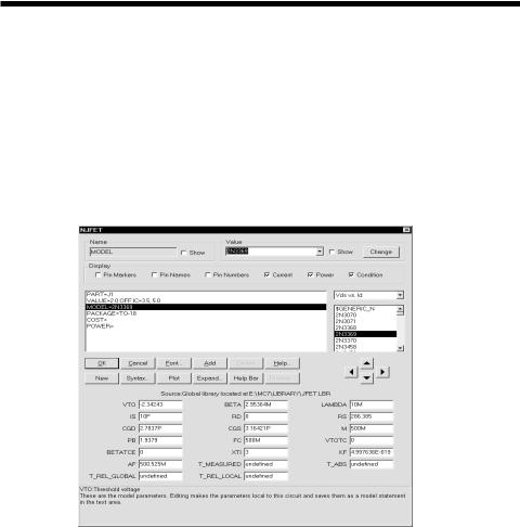
When you add a component that has not been modeled, the Attribute dialog box is presented to let you enter certain component information. The exact information required varies with the component but generally a part name and a value are the minimum required for the simpler parts like resistors, capacitors, and inductors. More complex parts usually require a part name and a model statement. Digital parts sometimes require logic expressions, block names, or stimulus table names. The number of attributes is determined by the type of component. Figure 2-3 shows the dialog box as it appears for a typical NJFET primitive.
Attribute list box |
|
|
|
|
|
|
|
|
|
|
|
Change button |
||
|
|
|
|
|
|
|
|
|
|
|
||||
|
|
|
|
|
|
|
|
|
|
|
Plot selector |
|||
|
|
|
|
|
|
|
|
|
|
|
||||
|
|
|
|
|
|
|
|
|
|
|
|
|
|
Modellistbox |
|
|
|
|
|
|
|
|
|
|
|
|
|
|
|
Command buttons |
|
|
|
|
|
|
|
|
|
|
Navigate |
|||
Source of displayed |
|
|
|
|
|
|
|
|
|
|
buttons |
|||
|
|
|
|
|
|
|
|
|
|
|
|
|||
model information |
|
|
|
|
|
|
|
|
|
|
|
|||
Edit area for model |
|
|
|
|
|
|
|
|
|
|
|
|||
parameters, subcircuits, |
|
|
|
|
|
|
|
|
|
|
|
|||
etc. |
|
|
|
|
|
|
|
|
|
|
|
|||
Figure 2-3 The Attribute dialog box
The attributes are shown in the Attribute list box. For an NJFET transistor the attributes are: PART, VALUE, MODEL, PACKAGE, COST, and POWER. Each attribute has a name and a value as shown in the table.
Attribute Name |
Attribute Value |
PART |
J1 |
VALUE |
2.0 OFF IC=3.5, 5.0 |
MODEL |
2N3369 |
PACKAGE |
TO-18 |
The first attribute is the part name. The optional second attribute is a text string
28 Chapter 2: The Circuit Editor
describing the area, off flag, and initial conditions. The MODEL attribute specifies the model name which in turn specifies a set of model parameters which may be located locally within the circuit in the text or drawing areas of the schematic, or may be located globally in the libraries. The PACKAGE attribute specifies the physical package used by the part. Package information is used to create netlists for external PCB (Printed Circuit Board) programs.
The COST and POWER attributes specify the unit cost and power budget for the Bill of Materials report. This is a type of netlist report that shows the parts count, cost, and power budget of the circuit.
To edit a particular attribute value, select it by clicking on the attribute name in the Attribute list box. Next, click in the Value field and edit it as desired.
You can add other attributes. These have no effect on the electrical behavior of the device. To add an attribute, click on the Add button. This adds a new attribute and places the name 'USER' in the Name field. The Value field is left blank. You can then edit the attribute Name and Value fields.
To delete an attribute, select it by clicking on its name in the Attribute list box. Then click on the Delete button. Only user-added attributes may be deleted.
To change an attribute font, size, style, color, or effects, click on the Font button. This displays the Font dialog box. The Font dialog box lets you edit text features. It is described later in this chapter.
The Model list box displays a list of available model names from the libraries. You can scroll through the list and choose a model by clicking on it.
Command buttons provide the following functions:
OK: This accepts any edits that have been made and exits the dialog box.
Cancel: This cancels any edits that have been made and exits the dialog box.
Font: This lets you alter the font and style of the selected attribute.
Add: This adds a new attribute.
Delete: This deletes the selected attribute. Only user-added attributes may be deleted.
29
Help: This accesses the help topics for the Attribute dialog box.
New: If the MODEL attribute is currently selected, this creates a new model name local to the circuit. You can also create a new model simply by typing in a model name not already in the library.
Syntax: This displays the syntax for the primitive from the help file.
Plot: This produces zero to three plots for each basic part type (primitive). The plots are created on the fly from mini-simulations of test circuits designed to produce the plot in question. Some parts, like the Pulse source, have a simple simulation and a single plot (two cycles of its waveform). Others, like the NPN, have several plots that can be chosen from the plot selector. Some parts, like macros and subckts, have no plot at all. Once the plot is displayed, it responds dynamically to parameter edits.
Expand: This button causes the data field where the text cursor is located to expand into a much larger text box. This lets you enter or edit a large piece of text. Normally, this is used only when an attribute value field requires a very large body of text, as for example, a table source with many pairs of data or a digital stimulus with many entries. These situations can also be handled by simply entering an alias in the value field and adding a .define statement in the text area that equates the alias with the larger table.
Help Bar: This toggles the display of the Help bar. Its job is to give a brief explanation of the field, button, or control under the cursor.
Browse: This button lets you browse when working with FILE attributes.
The Edit area lets you edit model parameters, subcircuits, digital stimulus statements, and other model information.
The Show check boxes adjacent to the Name and Value fields let you control whether the selected attribute's name and value are displayed on the schematic. Normally the attribute name is not displayed and only some of the attribute values are. Typically, only the part attribute value (in this case 'J1') is displayed, although occasionally the model attribute value (in this case '2N3369') is also.
The Pin Markers check box controls the display of markers showing the location of the pin connection points where wires would connect the pin to other circuit nodes. This is helpful when the actual pin location is not obvious.
30 Chapter 2: The Circuit Editor
The Pin Names check box controls the display of pin names. Sometimes this is helpful for vendor-supplied subcircuit part models where node numbers are used instead of more meaningful names. Normally this option is turned off.
The Pin Numbers check box controls the display of package pin numbers. This is primarily used to identify the physical pin numbers for PCB work. Normally this option is turned off.
The Current check box controls the display of the last time domain current value for the part, if the Current display button  is enabled.
The Power check box controls the display of the last time domain power value for the part, if the Power display button  is enabled.
The Condition check box controls the display of the last time domain condition (ON, OFF, etc.) for the part, if the Condition display button  is enabled.
The Change button lets you copy the displayed attribute value to the attribute fields of parts selected from a list. For example, you could use this command to change all 2N2222 model attributes to 2N3903.
The Plot Selector lets you select from a list of characteristic plots for the device. Some devices have as many as three plots, while some have none.
The Navigate buttons scroll through other parts in the circuit. Each click on the left or right navigate button will display another part of the same type. Each click on the up or down navigate button will display a different part type.
31
Adding wires to a schematic
Wires are added to a schematic by dragging the mouse from one point to another. If the mouse moves horizontally or vertically a straight wire is created. If it moves diagonally a corner is created.
First step: Click on the Wire mode button  in the Tool bar.
Second step: Point the mouse at the desired starting position and press and hold the left mouse button down.
Third step: Drag the mouse to the desired end point of the wire and release the left mouse button.
Several points are worth keeping in mind:
•The segment orientation of a two-segment wire can be changed by clicking the right mouse button before the wire is completed (before the left mouse button is released).
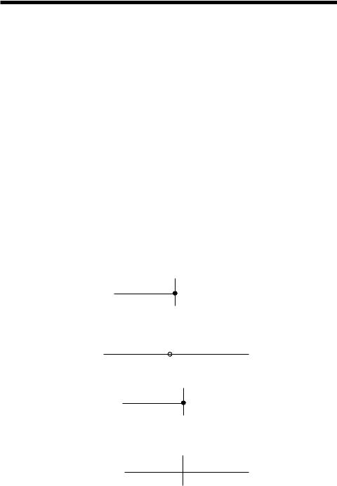
•Connections are indicated by a dot.
•If two wires are connected at their end points the wires fuse together and become one wire. The connection dot then disappears.
•If either end point of a wire touches another wire, the wires are connected.
•Wires that cross at interior points do not connect. An end point of a wire can connect only to another end point, a component lead, or an interior point of another wire.
32 Chapter 2: The Circuit Editor

•A wire that crosses another wire's end point or a component's lead dot will connect to the wire or component lead.
•If the Node Snap option is enabled, wires will snap to the nearest node within a one grid distance. Although this is usually helpful with analog parts, it is sometimes a problem with dense digital connections on a one grid pitch. You may want to temporarily disable this option if you notice a wire end point jumping to an undesired location. The Node Snap option is enabled or disabled from Options / Preferences / Common Options / Circuit / Node Snap.
•Although wires are the principal method of interconnecting nodes, grid text may also be used. Two nodes with the same piece of grid text placed on them are automatically connected together. This feature is especially useful in cases where you have many components sharing a common node, such as analog VDD and ground nodes, or digital clock, preset, and clear nodes.
•Holding the Shift key down after starting a wire forces the wire to stay horizontal or vertical, depending upon its principal direction prior to pressing the Shift key. It is necessary to press the Shift key after starting the wire, since pressing it before starting the wire would temporarily exit Wire mode and enter Select mode.
33

Adding and editing grid text
There are several kinds of text visible in a schematic. First, there is the attribute text of individual components. This type of text is created and edited from within the Attribute dialog box. The second kind of text is called grid text. Although grid text can be used for any purpose, its most important use is for naming nodes.
To add grid text to a schematic:
First step: Click on the Text mode button  in the Tool bar.
Second step: Click the mouse in the schematic where you want to add the text. A Text dialog box will appear. It offers the following options:
Figure 2-4 The Text dialog box
Command buttons
OK: This accepts user text entry or edits and places the new or edited text at the mouse site.
Cancel: This ignores any user edits and exits the dialog box.
Help: This accesses the Help system.
Options
Text: This lets you edit the text content.
34 Chapter 2: The Circuit Editor
Patterns: This lets you edit the text color, fill (background) color, and the border width and color.
Orientation: This lets you edit the print order / orientation. There are four choices. Normal specifies left to right order. Up specifies bottom to top order. Down specifies top to bottom order. Upside Down specifies right to left order and upside down orientation.
Font: This lets you edit the text font, size, style, and effects.
Stepping: These options are present only when adding text. They let you add multiple rows and/or columns of incremented text.
Instances X: This sets the number of rows of text.
Pitch X: This specifies the spacing in number of grids between rows of text.
Instances Y: This sets the number of columns of text.
Pitch Y: This specifies the spacing in number of grids between columns of text.
Stepping is used to name wires or nodes with grid text. For example, if you wanted sixteen names A0, ... A15 vertically arranged, you enter text of "A0", select Instances X = 1, Instances Y = 16, and Pitch Y = 2 (grids).
To add or edit existing text, select the Text panel of the dialog box. Type in or edit the text and press ENTER. To make a piece of text start on a new line place the insertion point text cursor at the desired position and press ENTER.
Grid text can be moved between text and drawing areas by selecting the text, then pressing CTRL + B. The display of the schematic window can be toggled between the text and drawing areas by typing CTRL + G.
To edit grid text:
First step: Click on the Select mode button  in the Tool bar.
Second step: Double-click the mouse on the text you want to edit. A Text dialog box will appear showing the selected text. Edit the text as desired.
35

Formula text
MC7 provides a special kind of schematic grid text that can be used to calculate formulas. Its form is as follows:
=formula
Grid text of this form behaves like a small spreadsheet. The presence of the "=" at the first character position tells MC7 that the text is really a formula and that it should calculate the value of the formula every time there is any change to schematic text. For example, the following four pieces of text define three variables, L1, C1, and C2 and a piece of formula text:
.DEFINE C1 1N
.DEFINE C2 1N
.DEFINE L1 10U =2*PI/SQRT(L1*C1*C2/(C1+C2))
Note that these are individual pieces of text, not a single block of text. The formula text must be placed in the schematic, not the text area. The .define statements may be placed in either the text area or in the schematic.
The formula is for the resonant frequency of a Colpitts oscillator. Any change to any text updates the value and MC7 prints the following:
2*PI/SQRT(L1*C1*C2/(C1+C2))=88.857E6
Formula text is designed to provide a convenient way to automatically compute and display new design values from complicated formulas. For example, if you change the value of C1 to 10nF, MC7 prints a new resonant frequency as follows:
2*PI/SQRT(L1*C1*C2/(C1+C2))=65.898E6
Formula text is entirely visual. The values can not be used in other expressions. To do that the formula must be defined with a symbolic variable name like this:
.DEFINE F0 2*PI/SQRT(L1*C1*C2/(C1+C2))
F0 could now be used in an expression or in, for example, a capacitor's VALUE attribute.
36 Chapter 2: The Circuit Editor