

13.5 Transforming I/O Requests to Hardware Operations |
611 |
13.5 Transforming I/O Requests to Hardware Operations
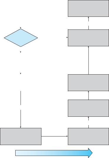
Earlier, we described the handshaking between a device driver and a device controller, but we did not explain how the operating system connects an application request to a set of network wires or to a specific disk sector. Consider, for example, reading a file from disk. The application refers to the data by a file name. Within a disk, the file system maps from the file name through the file-system directories to obtain the space allocation of the file. For instance, in MS-DOS, the name maps to a number that indicates an entry in the file-access table, and that table entry tells which disk blocks are allocated to the file. In UNIX, the name maps to an inode number, and the corresponding inode contains the space-allocation information. But how is the connection made from the file name to the disk controller (the hardware port address or the memory-mapped controller registers)?
One method is that used by MS-DOS, a relatively simple operating system. The first part of an MS-DOS file name, preceding the colon, is a string that identifies a specific hardware device. For example, C: is the first part of every file name on the primary hard disk. The fact that C: represents the primary hard disk is built into the operating system; C: is mapped to a specific port address through a device table. Because of the colon separator, the device name space is separate from the file-system name space. This separation makes it easy for the operating system to associate extra functionality with each device. For instance, it is easy to invoke spooling on any files written to the printer.
If, instead, the device name space is incorporated in the regular file-system name space, as it is in UNIX, the normal file-system name services are provided automatically. If the file system provides ownership and access control to all file names, then devices have owners and access control. Since files are stored on devices, such an interface provides access to the I/O system at two levels. Names can be used to access the devices themselves or to access the files stored on the devices.
UNIX represents device names in the regular file-system name space. Unlike an MS-DOS file name, which has a colon separator, a UNIX path name has no clear separation of the device portion. In fact, no part of the path name is the name of a device. UNIX has a mount table that associates prefixes of path names with specific device names. To resolve a path name, UNIX looks up the name in the mount table to find the longest matching prefix; the corresponding entry in the mount table gives the device name. This device name also has the form of a name in the file-system name space. When UNIX looks up this name in the file-system directory structures, it finds not an inode number but a <major, minor> device number. The major device number identifies a device driver that should be called to handle I/O to this device. The minor device number is passed to the device driver to index into a device table. The corresponding device-table entry gives the port address or the memory-mapped address of the device controller.
Modern operating systems gain significant flexibility from the multiple stages of lookup tables in the path between a request and a physical device controller. The mechanisms that pass requests between applications and drivers are general. Thus, we can introduce new devices and drivers into a computer without recompiling the kernel. In fact, some operating systems have the ability to load device drivers on demand. At boot time, the system
13.6 STREAMS 613
3.Otherwise, a physical I/O must be performed. The process is removed from the run queue and is placed on the wait queue for the device, and the I/O request is scheduled. Eventually, the I/O subsystem sends the request to the device driver. Depending on the operating system, the request is sent via a subroutine call or an in-kernel message.
4.The device driver allocates kernel buffer space to receive the data and schedules the I/O. Eventually, the driver sends commands to the device controller by writing into the device-control registers.
5.The device controller operates the device hardware to perform the data transfer.
6.The driver may poll for status and data, or it may have set up a DMA transfer into kernel memory. We assume that the transfer is managed by a DMA controller, which generates an interrupt when the transfer completes.
7.The correct interrupt handler receives the interrupt via the interruptvector table, stores any necessary data, signals the device driver, and returns from the interrupt.
8.The device driver receives the signal, determines which I/O request has completed, determines the request’s status, and signals the kernel I/O subsystem that the request has been completed.
9.The kernel transfers data or return codes to the address space of the requesting process and moves the process from the wait queue back to the ready queue.
10.Moving the process to the ready queue unblocks the process. When the scheduler assigns the process to the CPU, the process resumes execution at the completion of the system call.
13.6STREAMS
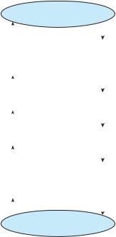
UNIX System V has an interesting mechanism, called STREAMS, that enables an application to assemble pipelines of driver code dynamically. A stream is
afull-duplex connection between a device driver and a user-level process. It consists of a stream head that interfaces with the user process, a driver end that controls the device, and zero or more stream modules between the stream head and the driver end. Each of these components contains a pair of queues
—a read queue and a write queue. Message passing is used to transfer data between queues. The STREAMS structure is shown in Figure 13.14.
Modules provide the functionality of STREAMS processing; they are pushed onto a stream by use of the ioctl() system call. For example, a process can open a serial-port device via a stream and can push on a module to handle input editing. Because messages are exchanged between queues in adjacent modules, a queue in one module may overflow an adjacent queue. To prevent this from occurring, a queue may support flow control. Without flow control,
aqueue accepts all messages and immediately sends them on to the queue in the adjacent module without buffering them. A queue that supports flow
614 |
Chapter 13 I/O Systems |
|
|
user process |
|||||
|
|
|
|
|
|
|
|
|
|
|
|
|
|
|
|
|
|
|
|
|
|
|
|
|
|
stream head |
|
|
|
||
|
|
|
|
|
|
||
read queue |
|
write queue |
|
|
|
||
|
|
|
|
|
|
||
|
|
|
|
|
|
|
|
|
|
|
|
|
|
|
|
read queue |
|
write queue |
|
|
|
||
|
|
|
|
|
STREAMS |
||
|
|
|
|
|
|
modules |
|
|
|
|
|
|
|||
read queue |
|
write queue |
|
|
|||
|
|
|
|
|
|
||
|
|
|
|
|
|
|
|
|
|
|
|
|
|
|
|
read queue |
|
write queue |
|
|
|
||
|
|
|
|
|
|
|
|
|
|
driver end |
|
|
|
||
|
|
|
|
|
|
|
|
|
|
|
|
|
|
|
|
|
|
device |
|||||
Figure 13.14 The STREAMS structure.
control buffers messages and does not accept messages without sufficient buffer space. This process involves exchanges of control messages between queues in adjacent modules.
A user process writes data to a device using either the write() or putmsg() system call. The write() system call writes raw data to the stream, whereas putmsg() allows the user process to specify a message. Regardless of the system call used by the user process, the stream head copies the data into a message and delivers it to the queue for the next module in line. This copying of messages continues until the message is copied to the driver end and hence the device. Similarly, the user process reads data from the stream head using either the read() or getmsg() system call. If read() is used, the stream head gets a message from its adjacent queue and returns ordinary data (an unstructured byte stream) to the process. If getmsg() is used, a message is returned to the process.
STREAMS I/O is asynchronous (or nonblocking) except when the user process communicates with the stream head. When writing to the stream, the user process will block, assuming the next queue uses flow control, until there is room to copy the message. Likewise, the user process will block when reading from the stream until data are available.
As mentioned, the driver end —like the stream head and modules —has a read and write queue. However, the driver end must respond to interrupts, such as one triggered when a frame is ready to be read from a network. Unlike the stream head, which may block if it is unable to copy a message to the next queue in line, the driver end must handle all incoming data. Drivers must support flow control as well. However, if a device’s buffer is full, the