

9.6 Thrashing |
425 |
computer systems, that is not the case. Often, in systems with multiple CPUs (Section 1.3.2), a given CPU can access some sections of main memory faster than it can access others. These performance differences are caused by how CPUs and memory are interconnected in the system. Frequently, such a system is made up of several system boards, each containing multiple CPUs and some memory. The system boards are interconnected in various ways, ranging from system buses to high-speed network connections like InfiniBand. As you might expect, the CPUs on a particular board can access the memory on that board with less delay than they can access memory on other boards in the system. Systems in which memory access times vary significantly are known collectively as non-uniform memory access (NUMA) systems, and without exception, they are slower than systems in which memory and CPUs are located on the same motherboard.
Managing which page frames are stored at which locations can significantly affect performance in NUMA systems. If we treat memory as uniform in such a system, CPUs may wait significantly longer for memory access than if we modify memory allocation algorithms to take NUMA into account. Similar changes must be made to the scheduling system. The goal of these changes is to have memory frames allocated “as close as possible” to the CPU on which the process is running. The definition of “close” is “with minimum latency,” which typically means on the same system board as the CPU.
The algorithmic changes consist of having the scheduler track the last CPU on which each process ran. If the scheduler tries to schedule each process onto its previous CPU, and the memory-management system tries to allocate frames for the process close to the CPU on which it is being scheduled, then improved cache hits and decreased memory access times will result.
The picture is more complicated once threads are added. For example, a process with many running threads may end up with those threads scheduled on many different system boards. How is the memory to be allocated in this case? Solaris solves the problem by creating lgroups (for “latency groups”) in the kernel. Each lgroup gathers together close CPUs and memory. In fact, there is a hierarchy of lgroups based on the amount of latency between the groups. Solaris tries to schedule all threads of a process and allocate all memory of a process within an lgroup. If that is not possible, it picks nearby lgroups for the rest of the resources needed. This practice minimizes overall memory latency and maximizes CPU cache hit rates.
9.6Thrashing
If the number of frames allocated to a low-priority process falls below the minimum number required by the computer architecture, we must suspend that process’s execution. We should then page out its remaining pages, freeing all its allocated frames. This provision introduces a swap-in, swap-out level of intermediate CPU scheduling.
In fact, look at any process that does not have “enough” frames. If the process does not have the number of frames it needs to support pages in active use, it will quickly page-fault. At this point, it must replace some page. However, since all its pages are in active use, it must replace a page that will be needed again right away. Consequently, it quickly faults again, and again, and again, replacing pages that it must bring back in immediately.

9.6 Thrashing |
427 |
We can limit the effects of thrashing by using a local replacement algorithm (or priority replacement algorithm). With local replacement, if one process starts thrashing, it cannot steal frames from another process and cause the latter to thrash as well. However, the problem is not entirely solved. If processes are thrashing, they will be in the queue for the paging device most of the time. The average service time for a page fault will increase because of the longer average queue for the paging device. Thus, the effective access time will increase even for a process that is not thrashing.
To prevent thrashing, we must provide a process with as many frames as it needs. But how do we know how many frames it “needs”? There are several techniques. The working-set strategy (Section 9.6.2) starts by looking at how many frames a process is actually using. This approach defines the locality model of process execution.
The locality model states that, as a process executes, it moves from locality to locality. A locality is a set of pages that are actively used together (Figure 9.19). A program is generally composed of several different localities, which may overlap.
For example, when a function is called, it defines a new locality. In this locality, memory references are made to the instructions of the function call, its local variables, and a subset of the global variables. When we exit the function, the process leaves this locality, since the local variables and instructions of the function are no longer in active use. We may return to this locality later.
Thus, we see that localities are defined by the program structure and its data structures. The locality model states that all programs will exhibit this basic memory reference structure. Note that the locality model is the unstated principle behind the caching discussions so far in this book. If accesses to any types of data were random rather than patterned, caching would be useless.
Suppose we allocate enough frames to a process to accommodate its current locality. It will fault for the pages in its locality until all these pages are in memory; then, it will not fault again until it changes localities. If we do not allocate enough frames to accommodate the size of the current locality, the process will thrash, since it cannot keep in memory all the pages that it is actively using.
9.6.2Working-Set Model
As mentioned, the working-set model is based on the assumption of locality. This model uses a parameter, , to define the working-set window. The idea is to examine the most recent page references. The set of pages in the most recent page references is the working set (Figure 9.20). If a page is in active use, it will be in the working set. If it is no longer being used, it will drop from the working set time units after its last reference. Thus, the working set is an approximation of the program’s locality.
For example, given the sequence of memory references shown in Figure 9.20, if = 10 memory references, then the working set at time t1 is {1, 2, 5, 6, 7}. By time t2, the working set has changed to {3, 4}.
The accuracy of the working set depends on the selection of . If is too small, it will not encompass the entire locality; if is too large, it may overlap several localities. In the extreme, if is infinite, the working set is the set of pages touched during the process execution.


9.6 Thrashing |
429 |
page reference table
. . . 2 6 1 5 7 7 7 7 5 1 6 2 3 4 1 2 3 4 4 4 3 4 3 4 4 4 1 3 2 3 4 4 4 3 4 4 4 . . .
t 1 |
t 2 |
WS(t 1) = {1,2,5,6,7} |
WS(t 2) = {3,4} |
Figure 9.20 Working-set model.
that working set enough frames to provide it with its working-set size. If there are enough extra frames, another process can be initiated. If the sum of the working-set sizes increases, exceeding the total number of available frames, the operating system selects a process to suspend. The process’s pages are written out (swapped), and its frames are reallocated to other processes. The suspended process can be restarted later.
This working-set strategy prevents thrashing while keeping the degree of multiprogramming as high as possible. Thus, it optimizes CPU utilization. The difficulty with the working-set model is keeping track of the working set. The working-set window is a moving window. At each memory reference, a new reference appears at one end, and the oldest reference drops off the other end. A page is in the working set if it is referenced anywhere in the working-set window.
We can approximate the working-set model with a fixed-interval timer interrupt and a reference bit. For example, assume that equals 10,000 references and that we can cause a timer interrupt every 5,000 references. When we get a timer interrupt, we copy and clear the reference-bit values for each page. Thus, if a page fault occurs, we can examine the current reference bit and two in-memory bits to determine whether a page was used within the last 10,000 to 15,000 references. If it was used, at least one of these bits will be on. If it has not been used, these bits will be off. Pages with at least one bit on will be considered to be in the working set.
Note that this arrangement is not entirely accurate, because we cannot tell where, within an interval of 5,000, a reference occurred. We can reduce the uncertainty by increasing the number of history bits and the frequency of interrupts (for example, 10 bits and interrupts every 1,000 references). However, the cost to service these more frequent interrupts will be correspondingly higher.
9.6.3Page-Fault Frequency
The working-set model is successful, and knowledge of the working set can be useful for prepaging (Section 9.9.1), but it seems a clumsy way to control thrashing. A strategy that uses the page-fault frequency (PFF) takes a more direct approach.
The specific problem is how to prevent thrashing. Thrashing has a high page-fault rate. Thus, we want to control the page-fault rate. When it is too high, we know that the process needs more frames. Conversely, if the page-fault rate is too low, then the process may have too many frames. We can establish upper and lower bounds on the desired page-fault rate (Figure 9.21). If the actual page-fault rate exceeds the upper limit, we allocate the process another

9.7 Memory-Mapped Files |
431 |
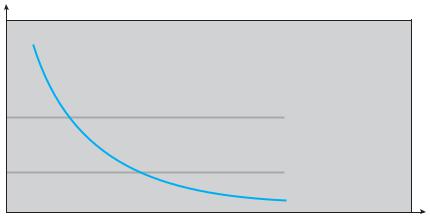
WORKING SETS AND PAGE-FAULT RATES
There is a direct relationship between the working set of a process and its page-fault rate. Typically, as shown in Figure 9.20, the working set of a process changes over time as references to data and code sections move from one locality to another. Assuming there is sufficient memory to store the working set of a process (that is, the process is not thrashing), the page-fault rate of the process will transition between peaks and valleys over time. This general behavior is shown below:
working set |
1 |
page |
fault |
rate |
0 |
time |
A peak in the page-fault rate occurs when we begin demand-paging a new locality. However, once the working set of this new locality is in memory, the page-fault rate falls. When the process moves to a new working set, the page-fault rate rises toward a peak once again, returning to a lower rate once the new working set is loaded into memory. The span of time between the start of one peak and the start of the next peak represents the transition from one working set to another.
in more than a page-sized chunk of memory at a time). Subsequent reads and writes to the file are handled as routine memory accesses. Manipulating files through memory rather than incurring the overhead of using the read() and write() system calls simplifies and speeds up file access and usage.
Note that writes to the file mapped in memory are not necessarily immediate (synchronous) writes to the file on disk. Some systems may choose to update the physical file when the operating system periodically checks whether the page in memory has been modified. When the file is closed, all the memory-mapped data are written back to disk and removed from the virtual memory of the process.
Some operating systems provide memory mapping only through a specific system call and use the standard system calls to perform all other file I/O. However, some systems choose to memory-map a file regardless of whether the file was specified as memory-mapped. Let’s take Solaris as an example. If a file is specified as memory-mapped (using the mmap() system call), Solaris maps the file into the address space of the process. If a file is opened and accessed using ordinary system calls, such as open(), read(), and write(),

432 |
Chapter 9 Virtual Memory |
|
|
|
|
|
1 |
|
|
|
2 |
|
|
|
3 |
|
1 |
|
4 |
|
2 |
3 |
5 |
|
3 |
|
6 |
|
4 |
|
|
|
5 |
6 |
|
|
6 |
|
|
|
process A |
1 |
process B |
|
5 |
||
|
virtual memory |
virtual memory |
|
|
|
4
2
physical memory
1 2 3 4 5 6
disk file
Figure 9.22 Memory-mapped files.
Solaris still memory-maps the file; however, the file is mapped to the kernel address space. Regardless of how the file is opened, then, Solaris treats all file I/O as memory-mapped, allowing file access to take place via the efficient memory subsystem.
Multiple processes may be allowed to map the same file concurrently, to allow sharing of data. Writes by any of the processes modify the data in virtual memory and can be seen by all others that map the same section of the file. Given our earlier discussions of virtual memory, it should be clear how the sharing of memory-mapped sections of memory is implemented: the virtual memory map of each sharing process points to the same page of physical memory —the page that holds a copy of the disk block. This memory sharing is illustrated in Figure 9.22. The memory-mapping system calls can also support copy-on-write functionality, allowing processes to share a file in read-only mode but to have their own copies of any data they modify. So that access to the shared data is coordinated, the processes involved might use one of the mechanisms for achieving mutual exclusion described in Chapter 5.
Quite often, shared memory is in fact implemented by memory mapping files. Under this scenario, processes can communicate using shared memory by having the communicating processes memory-map the same file into their virtual address spaces. The memory-mapped file serves as the region of shared memory between the communicating processes (Figure 9.23). We have already seen this in Section 3.4.1, where a POSIX shared memory object is created and each communicating process memory-maps the object into its address space. In the following section, we illustrate support in the Windows API for shared memory using memory-mapped files.

|
|
9.7 Memory-Mapped Files |
433 |
||
process1 |
|
|
|
process2 |
|
|
memory-mapped |
|
|
||
|
|
|
|||
shared |
|
|
|||
memory |
|
file |
|
|
|
|
|
shared |
|
|
|
|
|
|
|
|
|
|
|
memory |
|
|
|
|
|
|
|
shared |
|
|
|
|
|
|
|
|
|
|
|
memory |
|
|
|
|
|
|
|
|
|
|
|
|
|
Figure 9.23 Shared memory using memory-mapped I/O.
9.7.2Shared Memory in the Windows API
The general outline for creating a region of shared memory using memorymapped files in the Windows API involves first creating a file mapping for the file to be mapped and then establishing a view of the mapped file in a process’s virtual address space. A second process can then open and create a view of the mapped file in its virtual address space. The mapped file represents the shared-memory object that will enable communication to take place between the processes.
We next illustrate these steps in more detail. In this example, a producer process first creates a shared-memory object using the memory-mapping features available in the Windows API. The producer then writes a message to shared memory. After that, a consumer process opens a mapping to the shared-memory object and reads the message written by the consumer.
To establish a memory-mapped file, a process first opens the file to be mapped with the CreateFile() function, which returns a HANDLE to the opened file. The process then creates a mapping of this file HANDLE using the CreateFileMapping() function. Once the file mapping is established, the process then establishes a view of the mapped file in its virtual address space with the MapViewOfFile() function. The view of the mapped file represents the portion of the file being mapped in the virtual address space of the process
—the entire file or only a portion of it may be mapped. We illustrate this sequence in the program shown in Figure 9.24. (We eliminate much of the error checking for code brevity.)
The call to CreateFileMapping() creates a named shared-memory object called SharedObject. The consumer process will communicate using this shared-memory segment by creating a mapping to the same named object. The producer then creates a view of the memory-mapped file in its virtual address space. By passing the last three parameters the value 0, it indicates that the mapped view is the entire file. It could instead have passed values specifying an offset and size, thus creating a view containing only a subsection of the file. (It is important to note that the entire mapping may not be loaded into memory when the mapping is established. Rather, the mapped file may be demand-paged, thus bringing pages into memory only as they are accessed.) The MapViewOfFile() function returns a pointer to the shared-memory object; any accesses to this memory location are thus accesses to the memory-mapped

434 |
Chapter 9 Virtual Memory |
#include <windows.h> #include <stdio.h>
int main(int argc, char *argv[])
{
HANDLE hFile, hMapFile; LPVOID lpMapAddress;
hFile = CreateFile("temp.txt", /* file name */
GENERIC READ | GENERIC WRITE, /* read/write access */ 0, /* no sharing of the file */
NULL, /* default security */
OPEN ALWAYS, /* open new or existing file */
FILE ATTRIBUTE NORMAL, /* routine file attributes */ NULL); /* no file template */
hMapFile = CreateFileMapping(hFile, /* file handle */ NULL, /* default security */
PAGE READWRITE, /* read/write access to mapped pages */ 0, /* map entire file */
0,
TEXT("SharedObject")); /* named shared memory object */
lpMapAddress = MapViewOfFile(hMapFile, /* mapped object handle */ FILE MAP ALL ACCESS, /* read/write access */
0, /* mapped view of entire file */ 0, 0);
/* write to shared memory */ sprintf(lpMapAddress,"Shared memory message");
UnmapViewOfFile(lpMapAddress);
CloseHandle(hFile);
CloseHandle(hMapFile);
}
Figure 9.24 Producer writing to shared memory using the Windows API.
file. In this instance, the producer process writes the message “Shared memory message” to shared memory.
A program illustrating how the consumer process establishes a view of the named shared-memory object is shown in Figure 9.25. This program is somewhat simpler than the one shown in Figure 9.24, as all that is necessary is for the process to create a mapping to the existing named shared-memory object. The consumer process must also create a view of the mapped file, just as the producer process did in the program in Figure 9.24. The consumer then reads from shared memory the message “Shared memory message” that was written by the producer process.

9.7 Memory-Mapped Files |
435 |
#include <windows.h> #include <stdio.h>
int main(int argc, char *argv[])
{
HANDLE hMapFile; LPVOID lpMapAddress;
hMapFile = OpenFileMapping(FILE MAP ALL ACCESS, /* R/W access */ FALSE, /* no inheritance */
TEXT("SharedObject")); /* name of mapped file object */
lpMapAddress = MapViewOfFile(hMapFile, /* mapped object handle */ FILE MAP ALL ACCESS, /* read/write access */
0, /* mapped view of entire file */ 0, 0);
/* read from shared memory */ printf("Read message %s", lpMapAddress);
UnmapViewOfFile(lpMapAddress);
CloseHandle(hMapFile);
}
Figure 9.25 Consumer reading from shared memory using the Windows API.
Finally, both processes remove the view of the mapped file with a call to UnmapViewOfFile(). We provide a programming exercise at the end of this chapter using shared memory with memory mapping in the Windows API.
9.7.3Memory-Mapped I/O
In the case of I/O, as mentioned in Section 1.2.1, each I/O controller includes registers to hold commands and the data being transferred. Usually, special I/O instructions allow data transfers between these registers and system memory. To allow more convenient access to I/O devices, many computer architectures provide memory-mapped I/O. In this case, ranges of memory addresses are set aside and are mapped to the device registers. Reads and writes to these memory addresses cause the data to be transferred to and from the device registers. This method is appropriate for devices that have fast response times, such as video controllers. In the IBM PC, each location on the screen is mapped to a memory location. Displaying text on the screen is almost as easy as writing the text into the appropriate memory-mapped locations.
Memory-mapped I/O is also convenient for other devices, such as the serial and parallel ports used to connect modems and printers to a computer. The CPU transfers data through these kinds of devices by reading and writing a few device registers, called an I/O port. To send out a long string of bytes through a memory-mapped serial port, the CPU writes one data byte to the data register and sets a bit in the control register to signal that the byte is available. The device