


Bibliography 585
Are the inodes the same, or is each unique? Next, edit the contents of file4.txt. Have the contents of file3.txt been altered as well? Last, delete file3.txt. After you have done so, explain what happens when you attempt to edit file4.txt.
Bibliographical Notes
The MS-DOS FAT system is explained in [Norton and Wilton (1988)]. The internals of the BSD UNIX system are covered in full in [McKusick and Neville-Neil (2005)]. Details concerning file systems for Linux can be found in [Love (2010)]. The Google file system is described in [Ghemawat et al. (2003)].
FUSE can be found at http://fuse.sourceforge.net.
Log-structured file organizations for enhancing both performance and consistency are discussed in [Rosenblum and Ousterhout (1991)], [Seltzer et al. (1993)], and [Seltzer et al. (1995)]. Algorithms such as balanced trees (and much more) are covered by [Knuth (1998)] and [Cormen et al. (2009)]. [Silvers (2000)] discusses implementing the page cache in the NetBSD operating system. The ZFS source code for space maps can be found at http://src.opensolaris.org/source/xref/onnv/onnv-gate/usr/src/uts/common/ fs/zfs/space map.c.
The network file system (NFS) is discussed in [Callaghan (2000)]. NFS Version 4 is a standard described at http://www.ietf.org/rfc/rfc3530.txt. [Ousterhout (1991)] discusses the role of distributed state in networked file systems. Log-structured designs for networked file systems are proposed in [Hartman and Ousterhout (1995)] and [Thekkath et al. (1997)]. NFS and the UNIX file system (UFS) are described in [Vahalia (1996)] and [Mauro and McDougall (2007)]. The NTFS file system is explained in [Solomon (1998)]. The Ext3 file system used in Linux is described in [Mauerer (2008)] and the WAFL file system is covered in [Hitz et al. (1995)]. ZFS documentation can be found at http://www.opensolaris.org/os/community/ZFS/docs.
Bibliography
[Callaghan (2000)] B. Callaghan, NFS Illustrated, Addison-Wesley (2000).
[Cormen et al. (2009)] T. H. Cormen, C. E. Leiserson, R. L. Rivest, and C. Stein, Introduction to Algorithms, Third Edition, MIT Press (2009).
[Ghemawat et al. (2003)] S. Ghemawat, H. Gobioff, and S.-T. Leung, “The Google File System”, Proceedings of the ACM Symposium on Operating Systems Principles (2003).
[Hartman and Ousterhout (1995)] J. H. Hartman and J. K. Ousterhout, “The Zebra Striped Network File System”, ACM Transactions on Computer Systems, Volume 13, Number 3 (1995), pages 274–310.
[Hitz et al. (1995)] D. Hitz, J. Lau, and M. Malcolm, “File System Design for an NFS File Server Appliance”, Technical report, NetApp (1995).
586Chapter 12 File-System Implementation
[Knuth (1998)] D. E. Knuth, The Art of Computer Programming, Volume 3: Sorting and Searching, Second Edition, Addison-Wesley (1998).
[Love (2010)] R. Love, Linux Kernel Development, Third Edition, Developer’s Library (2010).
[Mauerer (2008)] W. Mauerer, Professional Linux Kernel Architecture, John Wiley and Sons (2008).
[Mauro and McDougall (2007)] J. Mauro and R. McDougall, Solaris Internals: Core Kernel Architecture, Prentice Hall (2007).
[McKusick and Neville-Neil (2005)] M. K. McKusick and G. V. Neville-Neil,
The Design and Implementation of the FreeBSD UNIX Operating System, Addison Wesley (2005).
[Norton and Wilton (1988)] P. Norton and R. Wilton, The New Peter Norton Programmer’s Guide to the IBM PC & PS/2, Microsoft Press (1988).
[Ousterhout (1991)] J. Ousterhout. “The Role of Distributed State”. In CMU Computer Science: a 25th Anniversary Commemorative, R. F. Rashid, Ed., AddisonWesley (1991).
[Rosenblum and Ousterhout (1991)] M. Rosenblum and J. K. Ousterhout, “The Design and Implementation of a Log-Structured File System”, Proceedings of the ACM Symposium on Operating Systems Principles (1991), pages 1–15.
[Seltzer et al. (1993)] M. I. Seltzer, K. Bostic, M. K. McKusick, and C. Staelin, “An Implementation of a Log-Structured File System for UNIX”, USENIX Winter (1993), pages 307–326.
[Seltzer et al. (1995)] M. I. Seltzer, K. A. Smith, H. Balakrishnan, J. Chang, S. McMains, and V. N. Padmanabhan, “File System Logging Versus Clustering: A Performance Comparison”, USENIX Winter (1995), pages 249–264.
[Silvers (2000)] C. Silvers, “UBC: An Efficient Unified I/O and Memory Caching Subsystem for NetBSD”, USENIX Annual Technical Conference — FREENIX Track
(2000).
[Solomon (1998)] D. A. Solomon, Inside Windows NT, Second Edition, Microsoft Press (1998).
[Thekkath et al. (1997)] C. A. Thekkath, T. Mann, and E. K. Lee, “Frangipani: A Scalable Distributed File System”, Symposium on Operating Systems Principles
(1997), pages 224–237.
[Vahalia (1996)] U. Vahalia, Unix Internals: The New Frontiers, Prentice Hall (1996).
C13H A P T E R
I/O Systems
The two main jobs of a computer are I/O and processing. In many cases, the main job is I/O, and the processing is merely incidental. For instance, when we browse a web page or edit a file, our immediate interest is to read or enter some information, not to compute an answer.
The role of the operating system in computer I/O is to manage and control I/O operations and I/O devices. Although related topics appear in other chapters, here we bring together the pieces to paint a complete picture of I/O. First, we describe the basics of I/O hardware, because the nature of the hardware interface places constraints on the internal facilities of the operating system. Next, we discuss the I/O services provided by the operating system and the embodiment of these services in the application I/O interface. Then, we explain how the operating system bridges the gap between the hardware interface and the application interface. We also discuss the UNIX System V STREAMS mechanism, which enables an application to assemble pipelines of driver code dynamically. Finally, we discuss the performance aspects of I/O and the principles of operating-system design that improve I/O performance.
CHAPTER OBJECTIVES
•To explore the structure of an operating system’s I/O subsystem.
•To discuss the principles and complexities of I/O hardware.
•To explain the performance aspects of I/O hardware and software.
13.1Overview
The control of devices connected to the computer is a major concern of operating-system designers. Because I/O devices vary so widely in their function and speed (consider a mouse, a hard disk, and a tape robot), varied methods are needed to control them. These methods form the I/O subsystem of the kernel, which separates the rest of the kernel from the complexities of managing I/O devices.
587
588 Chapter 13 I/O Systems
I/O-device technology exhibits two conflicting trends. On the one hand, we see increasing standardization of software and hardware interfaces. This trend helps us to incorporate improved device generations into existing computers and operating systems. On the other hand, we see an increasingly broad variety of I/O devices. Some new devices are so unlike previous devices that it is a challenge to incorporate them into our computers and operating systems. This challenge is met by a combination of hardware and software techniques. The basic I/O hardware elements, such as ports, buses, and device controllers, accommodate a wide variety of I/O devices. To encapsulate the details and oddities of different devices, the kernel of an operating system is structured to use device-driver modules. The device drivers present a uniform deviceaccess interface to the I/O subsystem, much as system calls provide a standard interface between the application and the operating system.
13.2 I/O Hardware
Computers operate a great many kinds of devices. Most fit into the general categories of storage devices (disks, tapes), transmission devices (network connections, Bluetooth), and human-interface devices (screen, keyboard, mouse, audio in and out). Other devices are more specialized, such as those involved in the steering of a jet. In these aircraft, a human gives input to the flight computer via a joystick and foot pedals, and the computer sends output commands that cause motors to move rudders and flaps and fuels to the engines. Despite the incredible variety of I/O devices, though, we need only a few concepts to understand how the devices are attached and how the software can control the hardware.
A device communicates with a computer system by sending signals over a cable or even through the air. The device communicates with the machine via a connection point, or port—for example, a serial port. If devices share a common set of wires, the connection is called a bus. A bus is a set of wires and a rigidly defined protocol that specifies a set of messages that can be sent on the wires. In terms of the electronics, the messages are conveyed by patterns of electrical voltages applied to the wires with defined timings. When device A has a cable that plugs into device B, and device B has a cable that plugs into device C, and device C plugs into a port on the computer, this arrangement is called a daisy chain. A daisy chain usually operates as a bus.
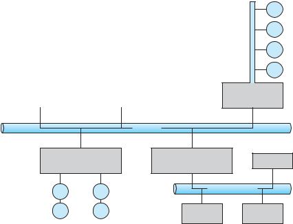
Buses are used widely in computer architecture and vary in their signaling methods, speed, throughput, and connection methods. A typical PC bus structure appears in Figure 13.1. In the figure, a PCI bus (the common PC system bus) connects the processor –memory subsystem to fast devices, and an expansion bus connects relatively slow devices, such as the keyboard and serial and USB ports. In the upper-right portion of the figure, four disks are connected together on a Small Computer System Interface (SCSI) bus plugged into a SCSI controller. Other common buses used to interconnect main parts of a computer include PCI Express (PCIe), with throughput of up to 16 GB per second, and HyperTransport, with throughput of up to 25 GB per second.
A controller is a collection of electronics that can operate a port, a bus, or a device. A serial-port controller is a simple device controller. It is a single chip (or portion of a chip) in the computer that controls the signals on the
590 |
Chapter 13 I/O Systems |
|
|
|
|
|
|
|
|
I/O address range (hexadecimal) |
device |
|
|
|
|
|
|
000–00F |
DMA controller |
|
|
|
|
|
|
020–021 |
interrupt controller |
|
|
|
|
|
|
040–043 |
timer |
|
|
|
|
|
|
200–20F |
game controller |
|
|
|
|
|
|
2F8–2FF |
serial port (secondary) |
|
|
|
|
|
|
320–32F |
hard-disk controller |
|
|
|
|
|
|
378–37F |
parallel port |
|
|
|
|
|
|
3D0–3DF |
graphics controller |
|
|
|
|
|
|
3F0–3F7 |
diskette-drive controller |
|
|
|
|
|
|
3F8–3FF |
serial port (primary) |
|
|
|
|
Figure 13.2 Device I/O port locations on PCs (partial).
mapped region to hold screen contents. The process sends output to the screen by writing data into the memory-mapped region. The controller generates the screen image based on the contents of this memory. This technique is simple to use. Moreover, writing millions of bytes to the graphics memory is faster than issuing millions of I/O instructions. But the ease of writing to a memory-mapped I/O controller is offset by a disadvantage. Because a common type of software fault is a write through an incorrect pointer to an unintended region of memory, a memory-mapped device register is vulnerable to accidental modification. Of course, protected memory helps to reduce this risk.
An I/O port typically consists of four registers, called the status, control, data-in, and data-out registers.
•The data-in register is read by the host to get input.
•The data-out register is written by the host to send output.
•The status register contains bits that can be read by the host. These bits indicate states, such as whether the current command has completed, whether a byte is available to be read from the data-in register, and whether a device error has occurred.
•The control register can be written by the host to start a command or to change the mode of a device. For instance, a certain bit in the control register of a serial port chooses between full-duplex and half-duplex communication, another bit enables parity checking, a third bit sets the word length to 7 or 8 bits, and other bits select one of the speeds supported by the serial port.
The data registers are typically 1 to 4 bytes in size. Some controllers have FIFO chips that can hold several bytes of input or output data to expand the capacity of the controller beyond the size of the data register. A FIFO chip can hold a small burst of data until the device or host is able to receive those data.
13.2 I/O Hardware |
591 |
13.2.1Polling
The complete protocol for interaction between the host and a controller can be intricate, but the basic handshaking notion is simple. We explain handshaking with an example. Assume that 2 bits are used to coordinate the producer –consumer relationship between the controller and the host. The controller indicates its state through the busy bit in the status register. (Recall that to set a bit means to write a 1 into the bit and to clear a bit means to write a 0 into it.) The controller sets the busy bit when it is busy working and clears the busy bit when it is ready to accept the next command. The host signals its wishes via the command-ready bit in the command register. The host sets the command-ready bit when a command is available for the controller to execute. For this example, the host writes output through a port, coordinating with the controller by handshaking as follows.
1.The host repeatedly reads the busy bit until that bit becomes clear.
2.The host sets the write bit in the command register and writes a byte into the data-out register.
3.The host sets the command-ready bit.
4.When the controller notices that the command-ready bit is set, it sets the busy bit.
5.The controller reads the command register and sees the write command. It reads the data-out register to get the byte and does the I/O to the device.
6.The controller clears the command-ready bit, clears the error bit in the status register to indicate that the device I/O succeeded, and clears the busy bit to indicate that it is finished.
This loop is repeated for each byte.
In step 1, the host is busy-waiting or polling: it is in a loop, reading the status register over and over until the busy bit becomes clear. If the controller and device are fast, this method is a reasonable one. But if the wait may be long, the host should probably switch to another task. How, then, does the host know when the controller has become idle? For some devices, the host must service the device quickly, or data will be lost. For instance, when data are streaming in on a serial port or from a keyboard, the small buffer on the controller will overflow and data will be lost if the host waits too long before returning to read the bytes.
In many computer architectures, three CPU-instruction cycles are sufficient to poll a device: read a device register, logical--and to extract a status bit, and branch if not zero. Clearly, the basic polling operation is efficient. But polling becomes inefficient when it is attempted repeatedly yet rarely finds a device ready for service, while other useful CPU processing remains undone. In such instances, it may be more efficient to arrange for the hardware controller to notify the CPU when the device becomes ready for service, rather than to require the CPU to poll repeatedly for an I/O completion. The hardware mechanism that enables a device to notify the CPU is called an interrupt.

592 |
Chapter 13 I/O Systems |
|
|
|
|
||||
|
|
|
|
CPU |
|
|
I/O controller |
||
|
1 |
|
|
|
|
||||
|
|
|
|
|
|
|
|
|
|
|
|
|
|
device driver initiates I/O |
2 |
|
|
||
|
|
|
|
|
|
||||
|
|
|
|
|
|
|
|
||
|
|
|
|
|
|
|
|
initiates I/O |
|
|
|
|
|
CPU executing checks for |
|
|
|
|
|
|
|
|
|
|
|
|
|
||
|
|
|
|
interrupts between instructions |
|
|
|
3 |
|
|
|
|
|
|
|
|
|
|
|
|
|
|
|
|
|
|
|
|
|
|
|
|
|
|
|
|
|
|
|
|
|
|
|
CPU receiving interrupt, |
4 |
input ready, output |
|||
|
|
|
|
transfers control to |
|
|
complete, or error |
||
|
|
|
|
|
|
||||
|
|
|
|
interrupt handler |
|
|
generates interrupt signal |
||
|
7 |
|
|
|
|
|
|
|
|
|
|
5 |
|
|
|
|
|||
|
|
|
|
|
|
|
|
||
|
|
|
|
|
|
|
|
|
|
|
|
|
|
|
|
|
|
|
|
|
|
|
|
interrupt handler |
|
|
|
|
|
|
|
|
|
processes data, |
|
|
|
|
|
|
|
|
|
returns from interrupt |
|
|
|
|
|
|
|
|
|
|
|
|
|
|
|
|
|
|
|
6 |
|
|
|
|
|
|
|
|
|
|
|
|
|
|
|
|
|
|
|
|
|
|
|
|
|
|
|
|
|
CPU resumes |
|
|
|
|
|
|
|
|
|
processing of |
|
|
|
|
|
|
|
|
|
|
|
|
|
||
|
|
|
|
interrupted task |
|
|
|
|
|
|
|
|
|
|
|
|
|
|
|
Figure 13.3 Interrupt-driven I/O cycle.
13.2.2 Interrupts
The basic interrupt mechanism works as follows. The CPU hardware has a wire called the interrupt-request line that the CPU senses after executing every instruction. When the CPU detects that a controller has asserted a signal on the interrupt-request line, the CPU performs a state save and jumps to the interrupt-handler routine at a fixed address in memory. The interrupt handler determines the cause of the interrupt, performs the necessary processing, performs a state restore, and executes a return from interrupt instruction to return the CPU to the execution state prior to the interrupt. We say that the device controller raises an interrupt by asserting a signal on the interrupt request line, the CPU catches the interrupt and dispatches it to the interrupt handler, and the handler clears the interrupt by servicing the device. Figure 13.3 summarizes the interrupt-driven I/O cycle. We stress interrupt management in this chapter because even single-user modern systems manage hundreds of interrupts per second and servers hundreds of thousands per second.
The basic interrupt mechanism just described enables the CPU to respond to an asynchronous event, as when a device controller becomes ready for service. In a modern operating system, however, we need more sophisticated interrupt-handling features.
13.2 I/O Hardware |
593 |
1.We need the ability to defer interrupt handling during critical processing.
2.We need an efficient way to dispatch to the proper interrupt handler for a device without first polling all the devices to see which one raised the interrupt.
3.We need multilevel interrupts, so that the operating system can distinguish between highand low-priority interrupts and can respond with the appropriate degree of urgency.
In modern computer hardware, these three features are provided by the CPU and by the interrupt-controller hardware.
Most CPUs have two interrupt request lines. One is the nonmaskable interrupt, which is reserved for events such as unrecoverable memory errors. The second interrupt line is maskable: it can be turned off by the CPU before the execution of critical instruction sequences that must not be interrupted. The maskable interrupt is used by device controllers to request service.
The interrupt mechanism accepts an address—a number that selects a specific interrupt-handling routine from a small set. In most architectures, this address is an offset in a table called the interrupt vector. This vector contains the memory addresses of specialized interrupt handlers. The purpose of a vectored interrupt mechanism is to reduce the need for a single interrupt handler to search all possible sources of interrupts to determine which one needs service. In practice, however, computers have more devices (and, hence, interrupt handlers) than they have address elements in the interrupt vector. A common way to solve this problem is to use interrupt chaining, in which each element in the interrupt vector points to the head of a list of interrupt handlers. When an interrupt is raised, the handlers on the corresponding list are called one by one, until one is found that can service the request. This structure is a compromise between the overhead of a huge interrupt table and the inefficiency of dispatching to a single interrupt handler.
Figure 13.4 illustrates the design of the interrupt vector for the Intel Pentium processor. The events from 0 to 31, which are nonmaskable, are used to signal various error conditions. The events from 32 to 255, which are maskable, are used for purposes such as device-generated interrupts.
The interrupt mechanism also implements a system of interrupt priority levels. These levels enable the CPU to defer the handling of low-priority interrupts without masking all interrupts and makes it possible for a highpriority interrupt to preempt the execution of a low-priority interrupt.
A modern operating system interacts with the interrupt mechanism in several ways. At boot time, the operating system probes the hardware buses to determine what devices are present and installs the corresponding interrupt handlers into the interrupt vector. During I/O, the various device controllers raise interrupts when they are ready for service. These interrupts signify that output has completed, or that input data are available, or that a failure has been detected. The interrupt mechanism is also used to handle a wide variety of exceptions, such as dividing by 0, accessing a protected or nonexistent memory address, or attempting to execute a privileged instruction from user mode. The events that trigger interrupts have a common property: they are occurrences that induce the operating system to execute an urgent, self-contained routine.
594 |
Chapter 13 I/O Systems |
|
|
|
|
|
|
|
|
vector number |
description |
|
|
|
|
|
|
0 |
divide error |
|
|
1 |
debug exception |
|
|
2 |
null interrupt |
|
|
3 |
breakpoint |
|
|
4 |
INTO-detected overflow |
|
|
5 |
bound range exception |
|
|
6 |
invalid opcode |
|
|
7 |
device not available |
|
|
8 |
double fault |
|
|
9 |
coprocessor segment overrun (reserved) |
|
|
10 |
invalid task state segment |
|
|
11 |
segment not present |
|
|
12 |
stack fault |
|
|
13 |
general protection |
|
|
14 |
page fault |
|
|
15 |
(Intel reserved, do not use) |
|
|
16 |
floating-point error |
|
|
17 |
alignment check |
|
|
18 |
machine check |
|
|
19–31 |
(Intel reserved, do not use) |
|
|
32–255 |
maskable interrupts |
|
|
|
|
Figure 13.4 Intel Pentium processor event-vector table.
An operating system has other good uses for an efficient hardware and software mechanism that saves a small amount of processor state and then calls a privileged routine in the kernel. For example, many operating systems use the interrupt mechanism for virtual memory paging. A page fault is an exception that raises an interrupt. The interrupt suspends the current process and jumps to the page-fault handler in the kernel. This handler saves the state of the process, moves the process to the wait queue, performs page-cache management, schedules an I/O operation to fetch the page, schedules another process to resume execution, and then returns from the interrupt.
Another example is found in the implementation of system calls. Usually, a program uses library calls to issue system calls. The library routines check the arguments given by the application, build a data structure to convey the arguments to the kernel, and then execute a special instruction called a software interrupt, or trap. This instruction has an operand that identifies the desired kernel service. When a process executes the trap instruction, the interrupt hardware saves the state of the user code, switches to kernel mode, and dispatches to the kernel routine that implements the requested service. The trap is given a relatively low interrupt priority compared with those assigned to device interrupts —executing a system call on behalf of an application is less urgent than servicing a device controller before its FIFO queue overflows and loses data.
Interrupts can also be used to manage the flow of control within the kernel. For example, consider one example of the processing required to complete
13.2 I/O Hardware |
595 |
a disk read. One step is to copy data from kernel space to the user buffer. This copying is time consuming but not urgent —it should not block other high-priority interrupt handling. Another step is to start the next pending I/O for that disk drive. This step has higher priority. If the disks are to be used efficiently, we need to start the next I/O as soon as the previous one completes. Consequently, a pair of interrupt handlers implements the kernel code that completes a disk read. The high-priority handler records the I/O status, clears the device interrupt, starts the next pending I/O, and raises a low-priority interrupt to complete the work. Later, when the CPU is not occupied with highpriority work, the low-priority interrupt will be dispatched. The corresponding handler completes the user-level I/O by copying data from kernel buffers to the application space and then calling the scheduler to place the application on the ready queue.
A threaded kernel architecture is well suited to implement multiple interrupt priorities and to enforce the precedence of interrupt handling over background processing in kernel and application routines. We illustrate this point with the Solaris kernel. In Solaris, interrupt handlers are executed as kernel threads. A range of high priorities is reserved for these threads. These priorities give interrupt handlers precedence over application code and kernel housekeeping and implement the priority relationships among interrupt handlers. The priorities cause the Solaris thread scheduler to preempt lowpriority interrupt handlers in favor of higher-priority ones, and the threaded implementation enables multiprocessor hardware to run several interrupt handlers concurrently. We describe the interrupt architecture of Windows XP and UNIX in Chapter 19 and Appendix A, respectively.
In summary, interrupts are used throughout modern operating systems to handle asynchronous events and to trap to supervisor-mode routines in the kernel. To enable the most urgent work to be done first, modern computers use a system of interrupt priorities. Device controllers, hardware faults, and system calls all raise interrupts to trigger kernel routines. Because interrupts are used so heavily for time-sensitive processing, efficient interrupt handling is required for good system performance.
13.2.3Direct Memory Access
For a device that does large transfers, such as a disk drive, it seems wasteful to use an expensive general-purpose processor to watch status bits and to feed data into a controller register one byte at a time —a process termed programmed I/O (PIO). Many computers avoid burdening the main CPU with PIO by offloading some of this work to a special-purpose processor called a direct-memory-access (DMA) controller. To initiate a DMA transfer, the host writes a DMA command block into memory. This block contains a pointer to the source of a transfer, a pointer to the destination of the transfer, and a count of the number of bytes to be transferred. The CPU writes the address of this command block to the DMA controller, then goes on with other work. The DMA controller proceeds to operate the memory bus directly, placing addresses on the bus to perform transfers without the help of the main CPU. A simple DMA controller is a standard component in all modern computers, from smartphones to mainframes.
