

Electronics_Projects_For_Dummies
.pdf60 Part I: Project Prep
Schematics help you understand how a particular electronics project works as well as how to build it. You can build the circuit on a breadboard (more on that in the upcoming section, “Breadboarding”) by inserting the components and making the connections on the board that are indicated by the schematic.
Perusing a simple schematic
An example of a very simple schematic shows a battery, one electronic component, and the wires connecting them. Figure 4-1 shows a schematic that contains a 1.5 volt battery, a wire from the positive side of the battery (+V) connecting it to one of the leads on an LED, and a wire connecting the other lead of the LED to the negative side of the battery. With both wires connected, current flows from one terminal of the battery through the LED, making it light up, and back to the other terminal of the battery. (If the LED is connected to only one battery terminal, no current flows, and the LED will not light up.)
+ |
1.5V |
LED1 |
- |
Figure 4-1:
A simple circuit with a battery.
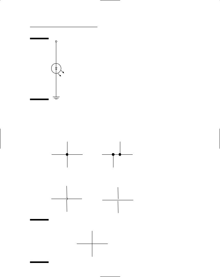
Some circuits use too many components for the schematic to show the wire connecting every component to the battery. In those cases, we use a convenient symbol for a voltage source to represent the positive side of the battery and a ground symbol to represent the negative side of the battery, as shown in Figure 4-2. This is same circuit as the preceding figure with a voltage source symbol and ground symbol representing connections to the battery. These symbols are also used in applications where a metal chassis is used as ground and a power supply is used to supply voltage.
You can read more about connecting to +V and ground in the later section, “The anatomy of a breadboard.”
Chapter 4: Running Down the Skills You Need 61
1.5V
Figure 4-2:
This circuit shows a voltage
source
symbol and LED1 ground
symbol representing connections
to the battery.
Interconnections among components (how wires are connected to move electricity from one component to another) in a circuit are made with wires or bits of copper placed on a breadboard. A schematic won’t usually specify which kind of connection you are using, only that a connection exists. Figure 4-3 shows a few methods of representing interconnections.
Connected |
Connected |
Unconnected |
Unconnected |
Figure 4-3:
How connections and nonconnections are represented in schematics.
UNKNOWN
62 Part I: Project Prep
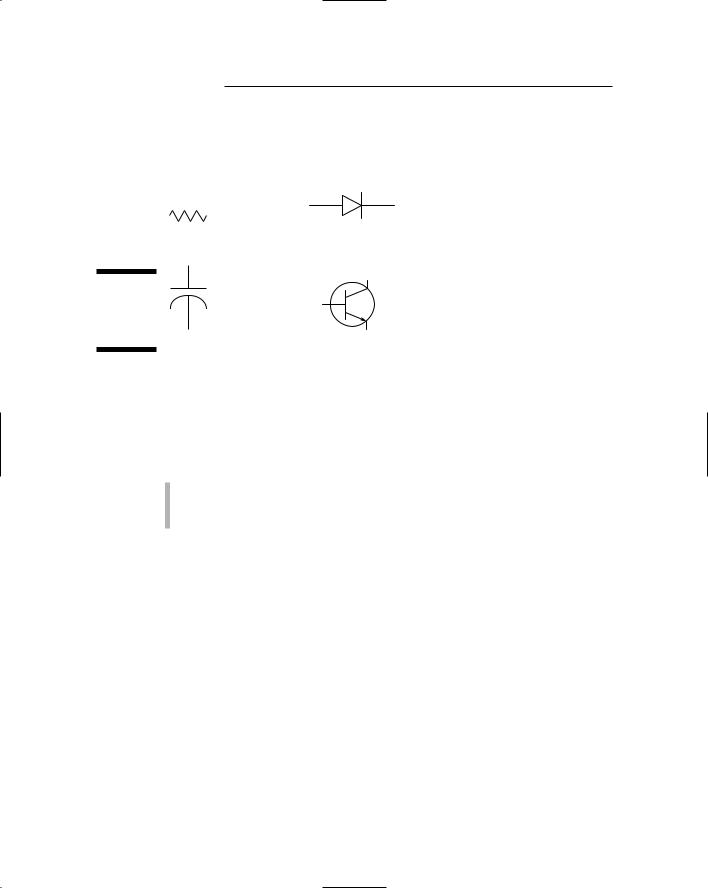
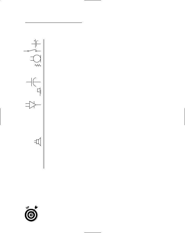
You’ll also find symbols for commonly used components, such as resistors, diodes, capacitors, and transistors, in schematics (see Figure 4-4). Chapter 3 explains what most of these components do in a circuit.
Resistor |
Diode |
Figure 4-4:
Common component symbols.
Capacitor |
Transistor |
Switching gears with switches
You use switches to turn power to a circuit on or off or to connect/disconnect a pin on a component to +V or ground. However, switches don’t use just a single symbol. Rather, they come in several varieties, indicating
How many wires they control
Whether they stay in the position you set them at or return to a normal position after you release them
An SPST (single-pole, single-throw) switch has one incoming wire and one outgoing wire that you use to open or close a connection in a circuit. For example, if a wire runs from the negative pole of a battery to an SPST switch and another wire runs from the SPST switch to a circuit, current can flow through the circuit when you have the switch in the closed position. When you flip the switch to the open position, no current can flow through the circuit.
SPST switches also come in the momentary switch variety; these can be normally open (NO) or normally closed (NC) and are generally controlled by pushbuttons or relays. A normally open switch conducts current only when the button is pressed and returns to its open position when it’s released. A normally closed switch won’t conduct current when you press the button but returns to its normal position and conducts current when you release it.
An SPDT (single-pole double-throw) switch has one incoming wire and two outgoing wires that you use to control which of two components is connected. Suppose that the incoming wire is connected to power, one outgoing wire is connected to a green LED, and the other outgoing wire is connected to a red LED. When you have the switch in one position, the green LED lights up; when you flip the switch, the green LED goes dark, and the red LED lights up.
Chapter 4: Running Down the Skills You Need 63
You can think of a DPDT (double-pole double-throw) switch as containing two SPDT switches that switch in tandem. To see an example of this in action, visit Chapter 13, where we use DPDT relays to simplify the wiring of our breadboard.
Schematic variables
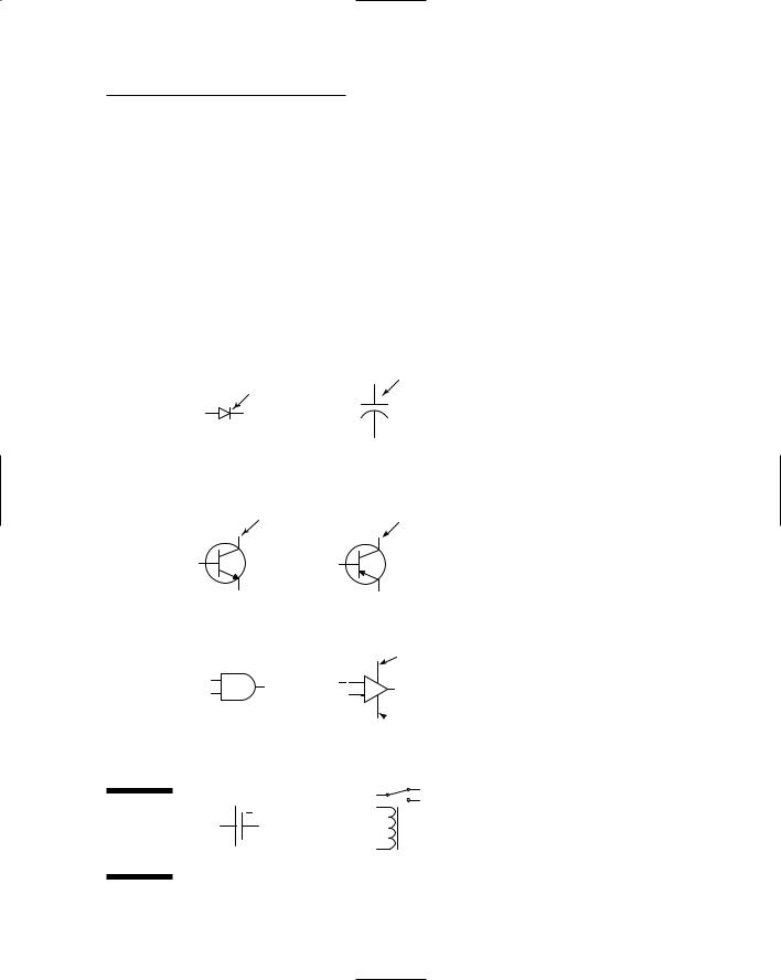
Some components are polarized, which means that you have to put them in the circuit in a particular way. Schematics can identify the polarity of components (see Figure 4-5).
Figure 4-5:
Common
polarity
symbols.
Negative
terminal
Diode
Positive terminal
NPN transistor
In |
Out |
AND gate
+
Battery
Positive terminal
+
Capacitor
Negative
terminal
PNP transistor
+ Supply
+Out

 Supply
OP amp
+
Relay
64 Part I: Project Prep
Identifying the + lead on polarized capacitors and LEDs is easy because the + lead is longer than the ground lead. For transistors and integrated circuits (ICs), you have to take a look at the datasheet to find out which pin to connect to +V and which pin to connect to ground. A datasheet is the manufacturer’s specifications for the component. You can read about pins in Chapter 3.
Some components are variable, meaning that they don’t just operate at one value; instead, you can adjust their values. Variable resistors (also called potentiometers), variable capacitors, and variable coils are all examples of adjustable components. You can use these adjustable items to control volume or tune in a radio station, for example.
Pulling it all together
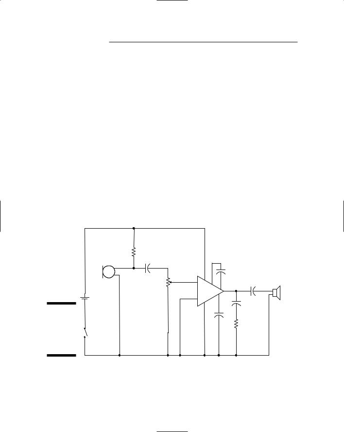
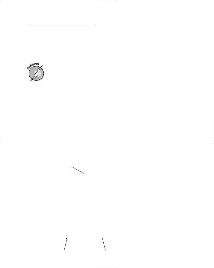
After you understand some of the elements that go into a schematic, we thought you’d like to have us rundown how to read a simple schematic sample. The schematic used in Chapter 6 is shown in Figure 4-6. This is a circuit that includes a microphone and an IC that amplify noises; the circuit works together with a parabolic (curved) metal dish that helps pick up sounds.
|
|
R1 |
|
|
|
|
|
|
|
|
|
|
|
+ |
|
|
|
C1 |
|
6 |
|
C2 |
|
|
|
|
|
|
|
||
|
MIC |
R2 |
|
1 |
|
|
C4 |
|
3 |
+ |
8 |
+ |
|||
|
|
|
IC1 |
|
|||
|
|
|
|
|
|
||
+ |
|
|
|
|
5 |
|
|
6V |
|
|
- |
7 |
|
||
|
|
|
|
||||
- |
|
2 |
C5 |
SPEAKER |
|||
|
|
|
|
4 |
|
||
Figure 4-6: |
|
|
|
|
+ |
||
|
|
|
|
|
|||
|
|
|
|
|
|
||
The |
|
|
|
|
|
C3 |
|
|
|
|
|
|
R3 |
|
|
schematic |
S1 |
|
|
|
|
|
|
used for the |
|
|
|
|
|
|
parabolic microphone.
First, some general rules: A line between two symbols indicates that the two components are connected by a wire. A connection is also indicated when a symbol is shown connected by one line to another line with a dot at the junction.
Chapter 4: Running Down the Skills You Need 65
Here’s what this schematic is saying:
A battery is used to supply 6 volts to the circuit.
S1 is an SPST switch that turns the power to the circuit on or off.
An electret microphone (MIC) transforms sound waves into electrical signals.
A resistor (R1) connects the microphone to the positive battery terminal and supplies the 3 volts required to make the microphone function. Note the dots above and below R1 that indicate connections.
C1 is a capacitor connected between R1 and R2.
R2 is a potentiometer with one lead connected to C1, one lead connected to the negative battery terminal, and the variable contact connected to Pin 3 of R2.
IC1 is an audio amplifier (op amp) connected at Pin 3 to R2.
Pins 2 and 4 of IC1 are connected to the negative battery terminal.
Pin 6 of IC1 is connected to the positive battery terminal.
Capacitor C2 is connected between Pins 1 and 8 of IC1. The positive side of the capacitor is connected to Pin 1.
Capacitor C3 is connected between Pin 7 of IC1and the negative battery terminal.
Capacitor C4 is connected between Pin 5 of IC1 and the speaker (or headphones).
Capacitor C5 is connected between Pin 5 of IC1 and resistor R3.
Resistor R3 is connected between capacitor C5 and the negative battery terminal.
The speaker (in this case, headphones) is connected between capacitor C4 and the negative battery terminal.
Breadboarding
A breadboard is a temporary place to build and test a circuit for an electronics project. You don’t have to solder the circuit; just insert components and the wires, connecting them into handy little holes.
When you’re sure you have your circuit right, you can create permanent boards by soldering or by ordering printed circuit boards. See Electronics For Dummies, by Gordon McComb and Earl Boysen (Wiley), for some detailed descriptions of these processes.
66 Part I: Project Prep
The anatomy of a breadboard
The breadboard itself is a plastic board with strips of metal running underneath and holes in the top. You slot the little wire legs that sprout from components and also the connecting wires into these holes, which contain metal channels called contacts. The metal strips that run underneath connect the items you plug into the holes to each other and the battery.
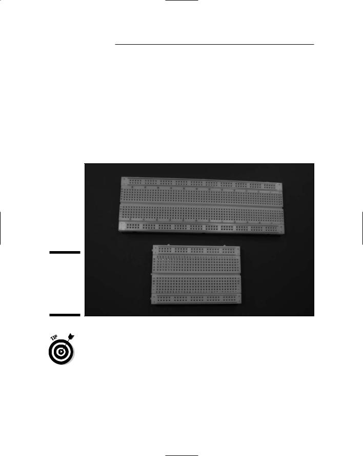
Breadboards come in various sizes; however, no matter what the size, the top and bottom rows of contacts on the breadboard (see Figure 4-7) are linked horizontally, and you’ll typically use them to connect to your battery.
Figure 4-7:
Your basic solderless breadboard in our two favorite sizes.
How to figure out what size breadboard to get? Some have as many as 3,200 contact points! But don’t overdo. For the projects in this book, we used boards with 400 contact points for small circuits and 830 contact points for medium circuits; for our large circuits, we hooked two boards together with the handy ridges and notches on the sides of the boards.
Notice the + and – (negative) signs on the breadboard. The positive battery terminal is connected to the rows with the + sign; these rows are often referred to as the +V bus. The negative battery terminal is connected to the rows with the – sign; these rows are often referred to as the ground bus. Because the +V bus and the ground bus run the entire length of the board on both sides, you need to use only a short piece of wire to reach a +V or ground bus from anywhere on the breadboard.
Chapter 4: Running Down the Skills You Need 67
Other contacts on the breadboard are linked vertically in rows of five; the five points are connected electrically by metal strips. Most folks place chips in the middle of the circuit, straddling the little aisle with each pin of the IC in a contact hole. That way, each pin of the IC is electrically connected to four other contacts, making it easy to connect other components to IC pins.
Don’t fry your board! These things are very susceptible to heat. Shorted components can melt them. Check the components with power on to make sure that nothing overheats. Also, they are designed only for low-voltage DC projects, so don’t apply too much juice.
Figuring and finessing the layout
How you arrange items on a breadboard won’t look exactly like how you’ve arranged items in a schematic. You have to pay attention to a few issues when laying out components on your breadboard. The schematic shows the elements of a circuit and connections, but a breadboard is arranged to make the most efficient connections possible using the holes and connectors available. Here are some tips to keep in mind.
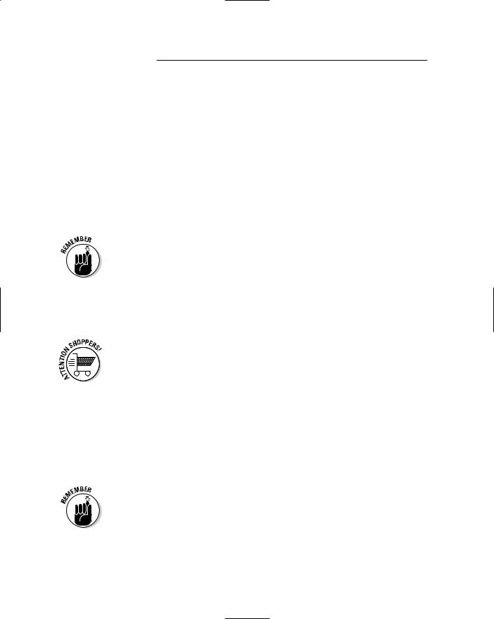
Pin numbering: ICs have pins that are numbered counterclockwise, starting at a little notch or dot indicator (see Figure 4-8). You should place all ICs pointing in the same direction. This helps you avoid inserting an IC backwards and also helps you keep track of the pin numbers. Use various pins, as specified on the IC datasheet, to connect to +V, ground, and other components.
Clocking mark
|
|
|
|
|
|
|
|
|
|
1 |
|
|
|
14 |
|
|
|
|
|
|
|
||
|
|
|
|
|
|
|
|
|
|
|
|
|
|
|
|
|
|
2 |
|
|
|
13 |
|
|
|
|
|
|
|
|
|
|
|
|
|
|
|
|
|
|
|
3 |
|
|
|
12 |
|
|
|
|
|
|
|
|
|
|
|
|
|
|
|
|
|
|
|
4 |
|
|
|
11 |
|
|
|
|
|
|
|
|
|
|
|
|
|
|
|
|
|
|
|
|
|
|
|
|
|
|
|
5 |
|
|
|
10 |
|
|
|
|
|
|
|
|
|
|
|
|
|
|
|
|
|
|
|
6 |
|
|
|
9 |
|
|
|
|
|
|
|
|
|
|
|
|
|
|
|
|
|
|
|
|
|
|
|
|
|
Figure 4-8: |
|
7 |
|
|
|
8 |
|
|
|
|
|
|
|
|
|
The IC pin |
|
|
|
|
|
|
|
numbering |
|
|
|
|
|
|
|
schematic. |
|
|
|
|
|
|
|
|
Pin numbers |
|
|
Pin numbers |
|||
|
|
|
|||||
68 Part I: Project Prep
Neatness counts: Take your time to make your board neat and tidy. This helps you to avoid mistakes and also helps you to troubleshoot if things aren’t working quite right.
Spacing: Leave yourself room to place items, allowing a little space between them. It’s better to leave a little more space between elements and use a bigger or expanded breadboard than to crowd yourself too much. This gives you the space to modify and refine your circuit.
Jumps: Minimize the jumps that you make between connections. (Typically, this involves using a jumper wire.) For example, if you can insert one lead of a component in the same row as the lead of another component you’re connecting to, you don’t have to use a jumper wire to connect them. The less wiring you have, the less messy things get.
Using color-coded wiring helps you to keep track of your layout. For example, many people use black wire for ground and red wire for power. Put wires at 90° angles, not on the diagonal, because diagonal wires will get in the way of other components to be placed on the board.
Also keep wires to a practical length: that is, long enough so you can route them around ICs but short enough so you don’t have lots of extra wire cluttering up your breadboard. (Routing wires around ICs means that if you have to remove or replace an IC, you don’t have to remove all the wires as well!)
Assorted lengths of prestripped wires are available that save you time in cutting, stripping, and bending wires to length. You just pick one that’s already cut to the right length. However, each length of these wires is a different color; thus, if you use prestripped wires, you can’t color-code your circuit. Because most of the photos in this book are black and white, we went for the convenience of using prestripped wires rather than color-coding the wires on the breadboard.
Inserting wires and components
In a nutshell, here’s how to wire a breadboard:
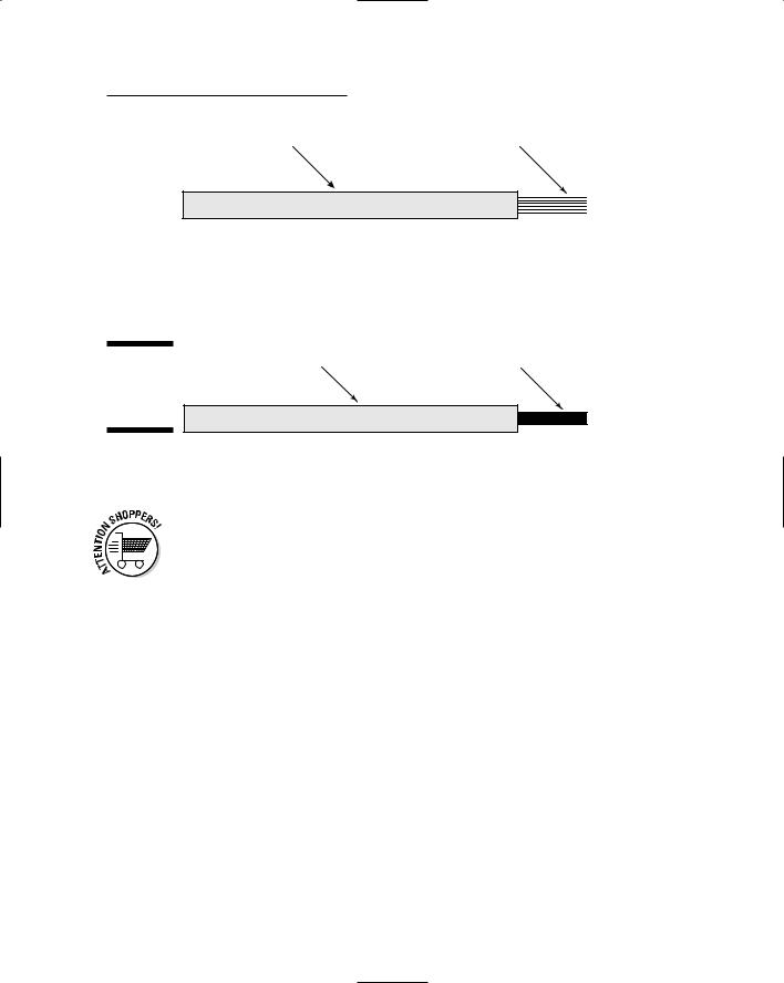
1.Use 22 gauge solid wire to make connections (see Figure 4-9).
Don’t use stranded wire because it can get smushed when you push it into a hole and could even cause shorts in your circuit if a piece of wire breaks off.
See the sidebar, “When stranded wire works,” for times when using stranded wires is more appropriate.
|
Chapter 4: Running Down the Skills You Need |
69 |
Insulation |
Several fine wires |
|
Stranded wire
Figure 4-9: |
Insulation |
Single wire |
Stranded versus solid wire.
Solid wire
2. Measure how long of a wire you need to make each connection. 3. Strip off 1⁄4" of insulation from each end.
Better yet, buy prestripped wires.
4. Bend the bare wire at a right angle.
5. Insert the wire into a hole in the board.
The schematic shown earlier in Figure 4-6 is shown translated onto a breadboard in Figure 4-10. You don’t see the potentiometer, microphone, battery, switch, or speaker on the breadboard because these are connected through wires attached to the five terminal blocks (TB). The sole purpose of a terminal block is to provide a place where you can attach wires to your circuit board by inserting them into holes and using a screw to clamp them down.
Notice that we inserted a lead from C2 into a contact in the same row as Pin 1 of IC1, thereby making electrical contact. We ran a wire from the same row as the other lead of C2 around IC1 to Pin 8 of IC1. This produces a lot neater board than you get when you loop wires over the IC.
Notice also how all the wires are flat on the breadboard. We cut them all to the length required so they didn’t have excess wire poking up in the air.
We measured the resistor leads so that we had enough length to cross the distance between the contacts and still have about 1⁄4" more on either side to bend down and insert in the breadboard holes.