

Electronics_Projects_For_Dummies
.pdf120 Part II: Sounding Off!
100 microfarad electrolytic capacitor (C4)
LM386N-1 amplifier IC1
Of the many versions of the LM386 amplifier, we chose the LM386N-1 because it is designed to work with the supply voltage of 6 volts required by this circuit.
Battery pack for 4 AA batteries
Edmund Scientific’s (www.edsci.com) 24"-diameter parabolic reflector, part #3053876
SPST toggle switch, used as the on/off switch
830-pin breadboard
Five 2-pin terminal blocks
Knobs for the potentiometer
Two phono jacks
Two right-angle phone plugs
We use right-angle plugs to avoid having a loop of wire coming out of the box. (You can also use something called a banana plug and jack.)
Headphones
We used a set of Philips HP170, but you can use any headphone you have available. Obviously, the better quality headphone you use, the better the sound quality.
Headphone jack
We used a 1⁄4" jack. If your headphone plug is a different size, use the appropriate size jack or get an adaptor.
Enclosure to protect the circuit
We used a plastic box, RadioShack part #2701807.
An assortment of different lengths of prestripped, short 22 AWG wire
PVC adaptor with 3⁄4" female slip fitting on one end and a 1" thread fitting on the other end
PVC 90° joint with a 1" slip fitting on both ends (one male and one female)
PVC adaptor 1" female slip fitting to a 1" female thread
PVC 1" end cap with a 1" female slip fitting
5⁄16"-diameter wooden dowel

Chapter 6: Focusing Sound with a Parabolic Microphone 121
Washer with a 1⁄4" inner diameter (ID) and 11⁄2" outer diameter (OD)
3⁄16" ID rubber 0-ring
1⁄4" thick rubber gasket material
1" diameter schedule 40 PVC pipe, 16" long
1" clamp
Four 1⁄2" 8-32 panhead screws
Four 8-32 nuts
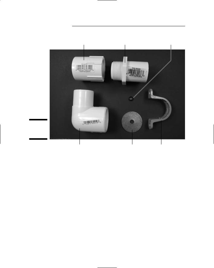
You should be able to find the last 12 parts on this list at your local building supply or hardware store. Take this book with you: The photos should help you pick out the right parts, and everybody who sees you with it will realize just how smart you are.
SPST toggle switch |
Phono jack |
Potentiometer |
Right-angle |
Microphone |
Electrolytic |
phono plug |
cartridge |
capacitor |
Figure 6-3:
Key components.
Ceramic capacitor |
IC |
Headphone jack |
122 Part II: Sounding Off!
PVC adaptor fitting |
PVC adaptor fitting |
|
1" slip fit to 1" thread |
3/4" slip fit to 1" thread |
3/16" ID rubber O-ring |
Figure 6-4:
More key components.
PVC 90° fitting |
¼" ID, |
1" clamp |
|
1½" OD washer |
|
Taking Things Step by Step
We’ve taken a lot of the pain out of this project for you by finding just the right microphone, the right dish size, headphones, and so on so that you can easily pick up distant sounds. This took many mornings of standing on either end of our street shouting, “Say that again; I couldn’t hear you!” Our neighbors still wonder about us, but it was worth it.
We further simplify your life by breaking down the process into a few easy steps.

Chapter 6: Focusing Sound with a Parabolic Microphone 123
Building an amplifier circuit
The first step in building a parabolic microphone is to tackle the circuit that forms its electronic brains. Here are the steps involved:
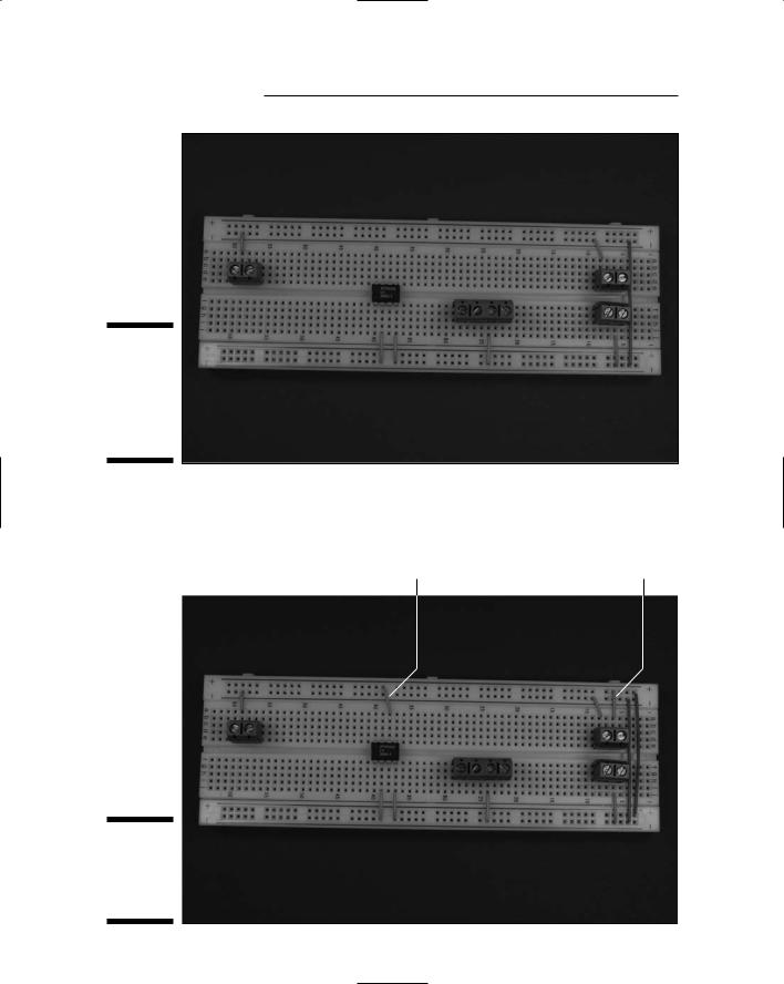
1.Place LM386N-1 (IC2) and five terminal blocks (TB) on the breadboard, as shown in Figure 6-5.
The five terminal blocks shown in this figure will be used to connect two wires each to various components in the circuit. The wires from these five terminal blocks will go to the battery pack, the on/off switch, the microphone, the speaker, and the potentiometer.
Figure 6-5:
Place the IC and terminal blocks on the
breadboard.
2.Insert wires to connect the IC and the terminal blocks to the ground bus and insert a wire between the two ground buses to connect them, as shown in Figure 6-6.
Six shorter wires connect components to ground bus; the long wire on the right connects the two ground buses.
124 Part II: Sounding Off!
Figure 6-6:
Connecting wires to the IC, terminal blocks, and ground buses.
3.Insert wires to connect the IC and the terminal blocks to +V, and a wire between the two +V buses to connect them, as shown in Figure 6-7.
Pin 6 of IC1 to +V |
Battery TB to +V |
Figure 6-7:
Connect components to the +V bus.

Chapter 6: Focusing Sound with a Parabolic Microphone 125
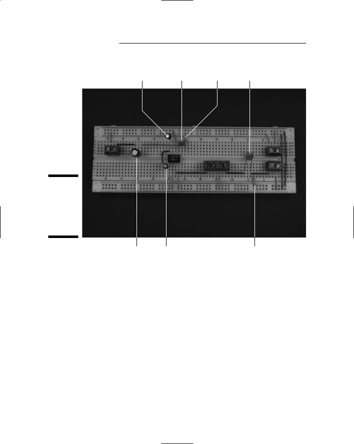
4.Insert wires to connect the ICs, terminal block for the microphone cartridge, terminal blocks for the potentiometer (R2), terminal block for the headphone jack, and discrete components, as shown in Figure 6-8.
Open region |
Pin 5 of IC1 |
to headphone jack TB |
to open region |
Figure 6-8:
Hook up the ICs, terminal blocks, and discrete components.
Pin 8 of IC1 |
R2 TB |
Open region |
Microphone TB |
to open region |
to Pin 3 of IC1 |
to R2 TB |
to open region |
5.Insert the 0.047 microfarad capacitor (C5), two 10 microfarad capacitors (C2 and C3), one 100 microfarad capacitor (C4), one 0.1 microfarad capacitor (C1), one 5.6 kohm resistor (R1), and one 10 ohm resistor (R3) on the breadboard, as shown in Figure 6-9.
When inserting electrolytic capacitors, be sure to check the schematic for where to insert the longer + lead.
We discuss in Chapter 4 how you can determine how short to clip the leads of many of these components to make them fit neatly on the breadboard. And you knew we were going to say it: Make sure you wear your safety glasses when clipping leads!
126 Part II: Sounding Off!
C3 from Pin 7 |
C5 from Pin 5 |
R3 |
C1 from |
of IC1 |
of IC1 |
from C5 |
microphone TB |
to ground |
to open region |
to ground |
to R2 TB |
Figure 6-9:
Insert resistors and capacitors on the breadboard.
C4 from Pin 5 of IC1 to headphone jack TB
C2 from Pin 1 of IC1 |
R1 from C1 |
to Pin 8 of IC1 |
to +V |
Mounting everything on the dish
Time to assemble the handle that allows you to hold the parabolic microphone. Figure 6-10 shows how the pieces (minus the parabolic dish itself) go together. When these fittings are assembled on the parabolic dish, the threads go through the hole in the center of the dish with one gasket inside the dish and one gasket outside the dish.

Chapter 6: Focusing Sound with a Parabolic Microphone 127
Gaskets 1" thread x 1" slip fitting
Figure 6-10:
Put the fittings together like this.
1" thread x ¾" slip fitting |
1" x 1" 90° slip fitting |
1" PVC pipe |
1.In the sheet of gasket material, cut a hole (using your utility knife or X-ACTO knife) large enough to slip over the 1" threads.
Use one of the PVC fittings as a template.
2.Use scissors to cut the outer diameter of the gasket about 3⁄8" larger than the inner diameter.
3. Repeat Steps 1 and 2 to create a second gasket.
Whenever you cut with a utility knife or an X-ACTO knife, wear leather work gloves to reduce the chance of cutting yourself if the knife slips.
4.Glue a 16", 1"-diameter PVC pipe into the female end of the 90° fitting.
5.Glue the male end of the 90° fitting into the slip fit end of the 1" x 1" fitting.

128 Part II: Sounding Off!
6.Drill a 3⁄8" hole about eight inches from the end in the side of the PVC pipe that will be to your left when you’re holding the parabolic
microphone.
You use this hole to feed the wires from the microphone cartridge to the box containing your circuit.
7.Slip one of the gaskets over the threads on the 1" x 3⁄4" fitting. Then slip the threads from the inside through the hole in the dish.
8.Slip the other gasket over the threads and then screw the 1" x 1" fitting onto the threads.
9.Tighten the fitting by hand so that the gaskets are compressed a little and the dish is held securely between the gaskets.
Figure 6-11 shows the handle assembled on the dish.
Figure 6-11:
Fittings assembled on the parabolic dish.
Mounting the microphone
The microphone is what makes this project work. The first step here is to make the microphone mounting. Follow these steps:

Chapter 6: Focusing Sound with a Parabolic Microphone 129
1.Cut four 6" pieces of wooden dowel.
2.Cut a slot about one-third of the way through each dowel, 1⁄4" from
an end.
The slot has to be wide enough for the washer to slip into.
3.Assemble the dowels and washer in the parabolic dish, as shown in Figure 6-12.
Use cable ties to hold the dowels in place. If you are doing this by yourself, it can be kind of a struggle, but it is doable. Getting another person to hold the dowels in place while you put the cable ties on it will simplify your life.
Figure 6-12:
Put together the microphone mounting.
4.Solder an 18" black wire to the ground pad of the microphone cartridge and an 18" red wire to the +V pad.
Figure 6-13 shows a cartridge before and after soldering.