

Electronics_Projects_For_Dummies
.pdf40 Part I: Project Prep
in farads (F). An F is pretty darn big, so you have to use prefixes to show lesser values. The prefixes used are micro- (millionth), nano- (thousand-millionth), and pico- (the ever-popular million-millionth).
Although you can find several kinds of capacitors — based on what material they are made of — three common types of capacitors you’ll run across in electronics projects are electrolytic, tantalum bead, and ceramic. Here’s are the basic characteristics of each:
Electrolytic capacitors are typically made of some kind of foil material, and you’ll find them with values of 1 microfarad and up. The two types are
•Axial: These have leads stuck on both ends.
•Radial: These have all the leads attached to the same end.
We use the axial type for the projects in this book because they take less room on a breadboard. The value of this type of capacitor is printed on it along with a voltage rating and its capacitance.
Be careful to check the voltage rating required by your project and choose a capacitor accordingly.
Tantalum (a metallic material) bead capacitors are available with values of 0.1 microfarad and higher. They cost more than the electrolytic capacitors but are useful if you have a circuit that requires more accuracy because tantalum capacitors have less variation in value than electrolytic capacitors.
Ceramic capacitors are nonpolarized (see the sidebar, “Polarized counts”), and you can find them with values from 1 picofarad to 0.47 microfarad. Reading the value on these tiny components can be difficult. And to add to the confusion, because many of these capacitors are too small to write the value on in words and numbers, folks use a code. Table 3-1 helps you spot common capacitor values based on their markings.
Polarized counts
Most electrolytic and tantalum capacitors are polarized, so you will see a polarity symbol on them. Typically, only one end is marked with either a plus or minus sign, so you can conclude that the other end is the opposite. With both types of capacitor, the longer lead is the positive one, which is probably the easiest way to identify it.
What’s important about being polarized? If a capacitor is polarized, you have to be absolutely
sure to install it the right way around in your circuit. If you don’t, you will be left with one dead capacitor and possible damage to other components in the circuit.
Small-value capacitors, typically made of ceramic or mica, are nonpolarized so you can connect them any way you want.
|
|
Chapter 3: Assembling Your Electronics Arsenal |
41 |
|
|
||
|
|
|
|
|
Table 3-1 |
Capacitor Values |
|
|
Marking |
Value |
|
|
101 |
0.0001 F |
|
|
|
|
|
|
102 |
0.001 F |
|
|
|
|
|
|
103 |
0.01 F |
|
|
|
|
|
|
471 |
0.00047 F |
|
|
|
|
|
|
472 |
0.0047 F |
|
|
|
|
|
|
473 |
0.047 F |
|
|
|
|
|
|
474 |
0.47 F |
|
|
|
|
|
For much more detail about various types of capacitors and how to read capacitor values, we recommend that you go out and buy Electronics For Dummies, by Gordon McComb and our own Earl Boysen (Wiley).
A final capacitor distinction that we have to make is variable versus fixed. All the capacitors we talked about so far are fixed, meaning they have a set value you can’t adjust. However, variable capacitors can by adjusted by various methods. We use a variable capacitor, for example, in Chapter 8 for tuning a radio.
Transistors
Transistors are the darlings of the electronics world. Transistors amplify a signal or voltage, or switch voltage on or off. The really amazing thing about transistors is how tiny they are: Before the advent of transistors, people used vacuum tubes to perform the same function, and a vacuum tube is huge in comparison. Transistors also use a lot less power.
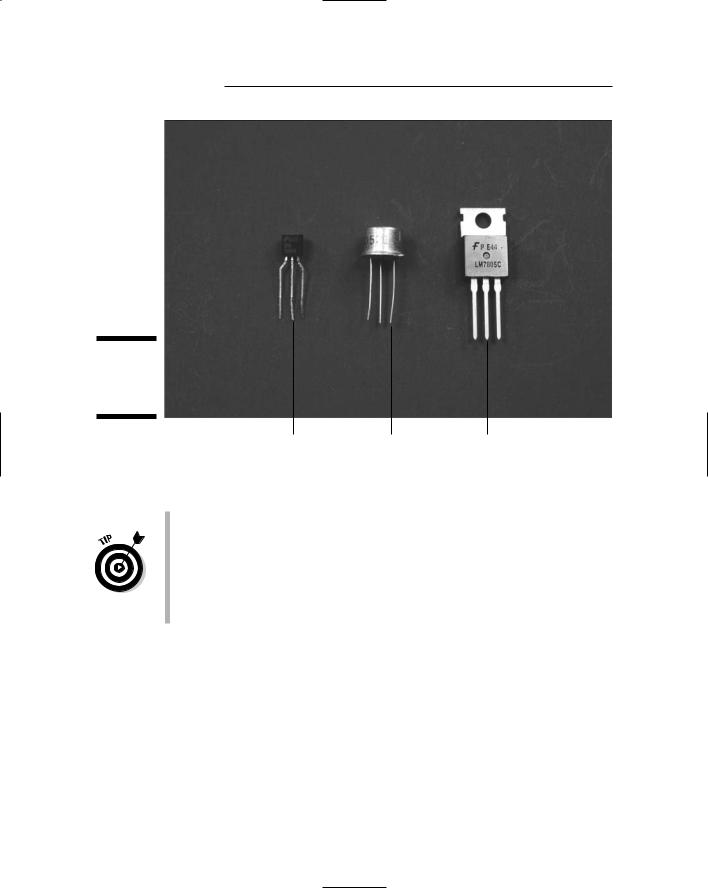
When you shop for transistors, be sure to check the package type. You can use packages starting with TO, such as TO-92, TO-39, and TO-220 (as shown in Figure 3-5) in breadboards or manually soldered circuit boards. Packages starting with SOT or SOIC are meant to be used on huge assembly lines and don’t have the types of leads that you can use easily in hobbyist electronics projects.
42 Part I: Project Prep
Figure 3-5:
Common transistor packages.
TO-92 |
TO-39 |
T0-220 |
Transistors come in
NPN (negative/positive/negative): You turn on NPN transistors by applying positive voltage; they start to turn on when you apply about 0.7 volts.
We use NPN transistors throughout this book because it’s more straightforward to apply a positive voltage to get things working.
PNP (positive/negative/positive): You turn off PNP transistors by applying positive voltage; they turn on when you apply negative voltages or voltages near ground.
Transistors have three leads: the emitter, base, and collector. In Chapter 4, we show you how to read schematics so you can figure out where to connect each pin. For each transistor you use, check the datasheet (which contains a drawing, called a pinout) to determine which pin is which.
ICs
Integrated circuits — commonly known as ICs — are like social directors for components: They gather lots of other components in a single location
Chapter 3: Assembling Your Electronics Arsenal |
43 |
(shuffleboard optional). ICs typically contain a number of transistors, resistors, and capacitors connected on a silicon chip to make a functional circuit in one small package.
ICs, as well as some other electrical components, can be susceptible to electrostatic discharge (in other words, zapping). For that reason, be sure to also get yourself an anti-static wrist strap (as we discuss in Chapter 2) for your electronics workshop.
ICs come in many packages
Manufacturers make ICs in many types of packages or containers. (A whole valley in California is dedicated to this type of thing.) The type of package that you use either in a breadboard or a circuit board is a dual inline package (DIP). A DIP is made up of plastic that encapsulates a silicon chip, with a row of metal leads running on either side of the plastic. You insert these leads into the contact holes in a breadboard and connect components on the breadboard with the circuitry on the silicon chip. (See the later section, “Breadboard Basics,” for more about this process.)
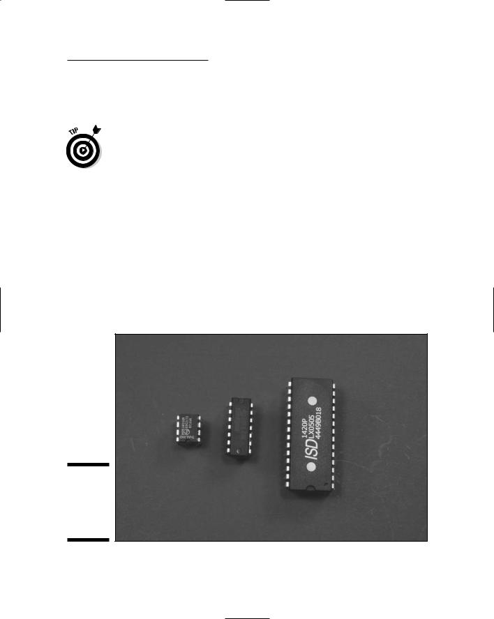
DIP ICs are identified by the number of leads they have, such as 8-pin DIP, 14-pin DIP, 16-pin DIP, 18-pin DIP, and so on. Figure 3-6 shows a few common DIP ICs.
Figure 3-6:
An assortment of DIP ICs (8-pin, 14-pin, and 28-pin).

44 Part I: Project Prep
When you order ICs, be careful to order an IC in a DIP package. If you obtain an IC in a non-DIP package, such as an SOIC (see the earlier section, “Transistors”), you can try forever, but you will never be able to insert the leads into a board. High-volume manufacturers use these other ICs with a technique called surface mounting. In this technique, the leads are soldered onto a contact on the surface of a circuit board, not inserted into a hole. If you really need to use an IC that comes only in a surface mount-type package, look for adapters to which you can solder the surface-mount IC and then insert the adapter into your board.
Because ICs are simply a collection of components (such as transistors, resistors, and capacitors) stuffed in miniature onto a silicon chip, each type of IC can perform a different function. That function depends on how many of each component is placed on the chip and how they are wired together. The next two sections provide an overview of two common ICs: operational amplifiers and audio amplifiers.
Opting for op amps
Operational amplifiers (affectionately known as op amps) are a type of IC that contains a series of transistors; each transistor amplifies the voltage of the signal just a bit more. You could build a multistage transistor amplifier that could do a similar job by using several transistors, capacitors, and resistors, but why bother? This setup would use about 50 times more space on your breadboard than a single 8-pin DIP op amp.
If you look in a catalog for op amps, you’ll probably see pages and pages of them — they’re that popular. The fact that we’re using 6 volt batteries to power our circuits narrows down the list considerably. Many op amps are designed to work with a positive supply voltage and a negative supply voltage, such as +6 volts and –6 volts. We use op amps in our projects that are designed to work with a 6 volt, or less, single-sided supply. An op amp that is designed to work with a single-sided supply needs only a positive supply voltage and ground.
Op amp ICs usually come in 8-pin DIPs; some of these have one op amp circuit, and some have two op amps (dual op amps). In a dual op amp, the pins that give access to one op amp are on the left side of the DIP, and the pins that give access to the other op amp are on the right side of the DIP. As you can see in the project in Chapter 7, this allows you to build one portion of your project circuit along the left side of the breadboard and a second portion along the right side of the breadboard, which can come in handy if things get overcrowded. Op amp ICs also come in 14-pin DIPs. These contain four separate op amps and are therefore called quad op amps.
Here are some common op amps used in electronics projects using low-volt- age batteries:
LM358: A dual op amp
LM324: A quad op amp
Chapter 3: Assembling Your Electronics Arsenal |
45 |
MC33171: A single op amp
MC33172: A dual op amp
MC33174: A quad op amp
Amplifying sound
Audio amplifiers are similar to op amps except that they are designed to provide more power; logically, being audio amps, they provide enough power to drive speakers.
The LM386 is a widely used audio amplifier. Different versions of the LM386 are designed to work with different supply voltages. For example, the LM386N-1, which we use in projects in Chapters 6 and 7, is designed to work with a 6 volt supply and can work with a supply voltage as low as 4 volts. The MC34119 is an audio amplifier that can work with a supply voltage as low as 2 volts.
ICs are available for many specialized uses; you can see some of them in action in the projects that we include in this book. The projects in Chapters 11 and 15, for example, use encoder/decoders ICs paired with motor driver ICs. The project in Chapter 10 uses a timer IC paired with a decade counter IC, and the project in Chapter 7 uses a speech synthesizer IC paired with an audio amplifier IC. The projects in Chapters 9 and 14 both use a voice recorder IC.
The switch is on
A switch seems simple enough: You flick it one way to go on and the other way to go off. However, understanding what’s happening behind that switch requires that we give you a bit of background.
Open: A switch is in an open state when there is no electrical connection. When switch is open, there is very high resistance between a wire coming into a switch and the wire going out of the switch.
Closed: A switch is closed when there is an electrical connection. When a switch is closed, there is very low resistance between a wire coming into a switch and the wire going out of the switch.
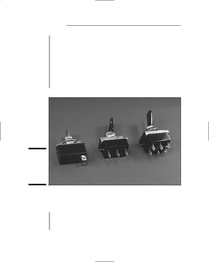
There are different kinds of switches, referred to as SPST, SPDT, and DPDT, as shown in Figure 3-7. Here’s what these catchy acronyms mean:
SPST (single-pole, single-throw): This kind of switch has two lugs to which you can solder wires. When the switch is on, the two wires are connected; when the switch is off, the two wires are disconnected. We like SPST switches so much that we use them as on/off switches in every project in this book.
SPDT (single-pole, double-throw): This kind of switch has three lugs to which you can solder wires: one for an incoming wire and two for
46 Part I: Project Prep
outgoing wires. When the switch is in one position, the incoming wire is connected to the first of the outgoing wires. When the switch is in the other position, the incoming wire is connected to the second of the outgoing wires. (If you have a different need and this is the type of switch you happen to have in your parts bin, you can use just two lugs to make it work as an SPST.)
DPDT (double-pole, double-throw): This kind of switch has six lugs to which you can solder wires. These lugs can be attached to two incoming wires and four outgoing wires. When you flip this switch, you simply switch each incoming wire between two of the outgoing wires. We use this type of switch in a relay in Chapter 13 to switch control of the motors from one type of sensor to another.
Figure 3-7:
Three types of switches from left to right: SPST, SPDT, and DPDT.
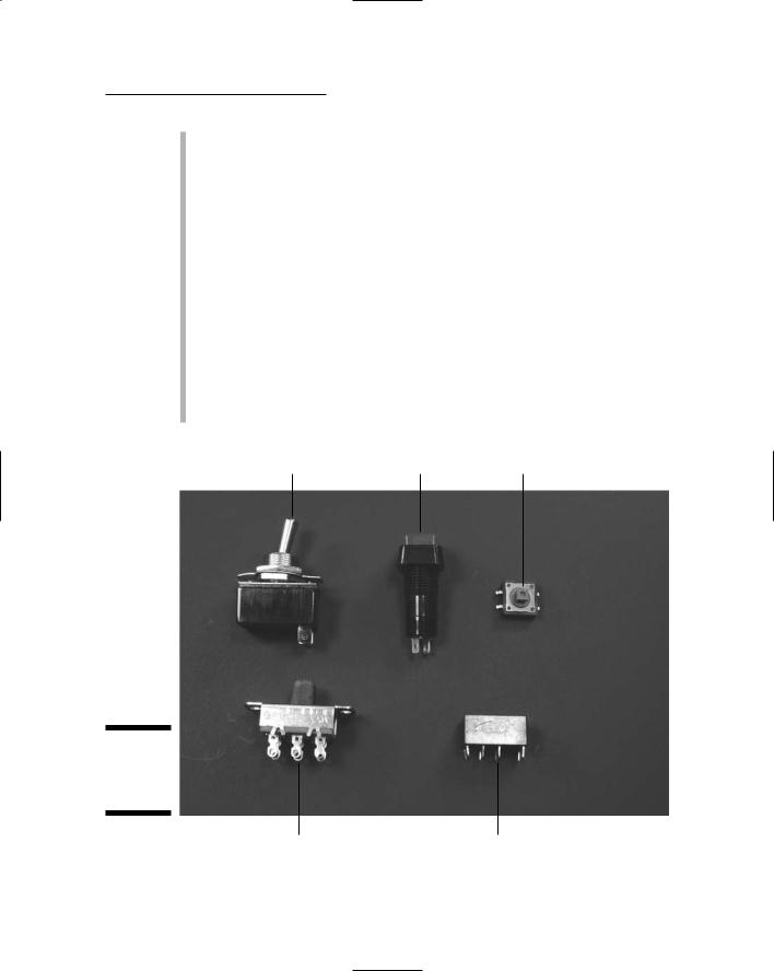
As if switches didn’t have enough names, they are also referred to by the method used to change their state from open to closed. See Figure 3-8 to see the different types.
Toggle switch: This switch gets its name from the fact that you flip a lever to turn it on and flip it back to turn it off.
Pushbutton on/off switch: Every time you push this button, it changes from on to off or vice versa.
Chapter 3: Assembling Your Electronics Arsenal |
47 |
Momentary pushbutton switch: Pushing this switch is what changes its state, but only for the moment! These are also classified by whether they are normally open (NO) or normally closed (NC). For example, a momentary normally open switch is closed only while you hold the pushbutton down. When you release the button, it goes back to its normal — open — state.
Tactile switch: This is a type of momentary pushbutton switch. Tactile switches are rated by the amount of force that is needed to push the button and are often flat so that they can be easily inserted somewhere without protruding (like how we insert them into the hands of a puppet in Chapter 7).
Slide switch: Logically, this switch operates when you slide a knob to change it from on to off or vice versa.
Relays: These switches are operated by a voltage rather than by pushing a switch. This makes them very useful for turning on or off a component, such as a light or motor, through a remote control or by voltage generated by a sensor. We control relays with both methods in Chapter 13.
Toggle switch |
Pushbutton switch Tactile switch |
Figure 3-8:
A plethora of ways to flip a switch.
Slide switch |
Relay switch |

48 Part I: Project Prep
Sensors
Sensors take energy in forms such as sound or light and transform that energy into a signal. By using a sensor, you can detect heat, light, and sound, for example. When a signal is sensed, to the sensor produces an electrical signal that is used by your circuit to control some activity. For example, an infrared detector can work in conjunction with an infrared remote control device to stop or start a little go-kart.
Here are a few types of sensors that we use in the projects in this book:
IR detector: This converts infrared (IR) light into an electric signal. The version that we use in Chapters 11 and 9 contains a photodiode that detects infrared light and an integrated circuit that produces either +V or 0 volts on its output pin. In order to reduce noise from ambient IR light, this detector is designed to only respond to IR light that is pulsed at 38 kHz.
Tilt/vibration sensor: This type of sensor (which we use in Chapter 14) detects motion or vibrations when the switch is mounted with the body of the sensor horizontal. When the sensor detects motion, it closes a switch, just like a toggle switch works.
Microphones
Technically speaking, a microphone is a kind of sensor. However, there’s a lot to say about these sound-sensing devices, so we give microphones their own section (because we’re the authors, and we can!).
How condenser (capacitor) microphones work
Capacitors are kind of like a voltage sandwich in that they have two plates, with a slab of voltage between them. A so-called condenser mike (also called a capacitor microphone) contains one plate made of a very light material that acts as a diaphragm. This plate vibrates when sound waves hit it. This moves the two plates apart, which changes capacitance (the ability to store electrons). Moving the plates farther apart decreases capacitance (discharging current), and moving them together increases capacitance (charging current).
Condenser microphones aren’t cheap, but they give high-quality sound, so they are often the best choice for an audio-intensive project.
A better mousetrap: Electret capacitor microphones
Today, the most popular type of condenser microphone is the electret microphone (which gets its name from the combination of electrostatic and magnet),

Chapter 3: Assembling Your Electronics Arsenal |
49 |
invented in 1962. The electret material used in this type of microphone is made by embedding a permanent charge in a material called a dielectric. A charge is embedded in a dielectric by aligning the charges in the material — sort of like how you make a magnet by aligning the atoms in a piece of iron.
There is a preamplifier in an electret microphone, to which you provide a supply voltage. That’s why the projects in this book that use electret microphones have a connection through a resistor running between the plus (+) lead of the microphone and the +V bus to power the preamplifier. (The resistor reduces the voltage at the + lead of the microphone to the desired supply voltage.)
Size counts
When you order electret microphones, pay attention to the diameter and thickness because some can be hard to handle and solder. For most of our projects in this book, we use microphones with a diameter of about 3⁄8" and a thickness of about 2⁄10". A microphone cartridge with a diameter of about 1⁄4" and a thickness of about 1⁄10" turns out to be much harder to handle and solder to than a microphone cartridge of about 3⁄8" and a thickness of about 2⁄10". (Check out Chapter 6, where we bit the bullet and used a small microphone cartridge because that project needed some of the capabilities we couldn’t find in a larger microphone cartridge.)
Many microphone cartridge sizes are specified in millimeters. To help you translate this, typical diameters of microphone casings are 6 mm (about 1⁄4") and 9.7 mm (about 3⁄8").
Measuring sensitivity
Sensitivity is another issue that you should pay attention to with microphone cartridges. Sensitivity is measured in decibels (dB) — and just to confuse you, this measurement is given as a negative number. A microphone cartridge with a sensitivity of –40 dB, for example, is more sensitive (provides higher voltage at a given level of sound) than a microphone cartridge with a sensitivity of –60.
For example, for the project in Chapter 6 (which has to pick up very faint sounds as part of a parabolic microphone), you need a highly sensitive microphone cartridge. We use one with a sensitivity of –35 dB. In Chapter 14, in which you talk directly into the microphone to record a message, we use a less-sensitive microphone cartridge, rated at –64 dB.
Connecting your microphone cartridge to your project
To connect electret microphone cartridges to your project, you can get electret microphone cartridges with solder pads or with leads that you can insert into a breadboard. We use both in our projects.