

Electronics_Projects_For_Dummies
.pdf110 Part II: Sounding Off!
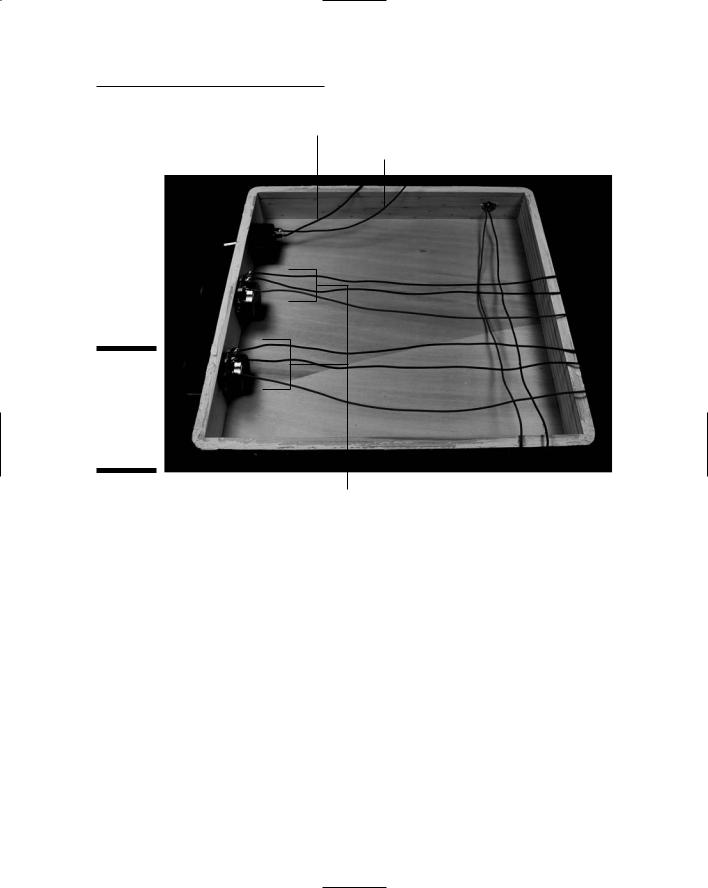
On/off switch |
Microphone |
Figure 5-22:
Box with on/ off switch, potentiometers, and microphone in place.
Potentiometers
11.Insert the wires from the LEDs, battery pack, and the on/off switch to the terminal blocks on the breadboard, as shown in Figure 5-24.
Use the following as a key to the numbered callouts in Figure 5-24.
1.Red wire from LED +V bus
2–5. Wires from pair of red LEDs 6–9. Wires from pair of green LEDs
10.Red wire from battery pack
11.Black wire from on/off switch
12.Red wire from microphone
13.Black wire from microphone
14 and 17. Wires from right potentiometer lug
15 and 18. Wires from center potentiometer lug
16 and 19. Wires from left potentiometer lug
Chapter 5: Making Light Dance to the Music 111
Black wire from battery pack to on/off switch
Black wire to on/off switch
Figure 5-23:
Wires soldered to the on/off switch and the potentiometers.
Wires to potentiometers
12.As you insert the wires, cut each of them to the length needed to reach the assigned terminal block and strip the insulation from the end of the wire.
13.Secure the wires with wire clips.
Trying It Out
Okay, you’ve been taking it on faith that this is going to be a cool project, and we appreciate it. But now it’s time to get the thing going and see whether you think it’s as much fun as we do.

112 Part II: Sounding Off!
|
3 |
|
|
|
|
|
6 |
|
|
|
|||||||
|
|
|
|
|
|
|
|||||||||||
|
|
|
|
|
|
|
|
|
|||||||||
|
2 |
|
|
|
|
|
1 |
|
|
|
|||||||
|
|
|
|
|
|
|
|
|
|||||||||
|
5 |
|
|
|
|
|
9 |
|
8 |
|
|||||||
|
|
|
|
|
|
||||||||||||
|
|
|
|
|
|
|
|||||||||||
|
4 |
|
|
|
|
|
|
|
|
|
|
|
|
|
7 |
||
|
|
|
|
|
|
|
|
|
|
|
|
|
|||||
|
|
|
|
|
|
|
|
|
|
|
|
|
|
|
|||
|
|
|
|
|
|
|
|
|
|
|
15 |
|
|
||||
Figure 5-24: |
18 |
|
|
|
|
|
|
|
|
14 |
|
||||||
|
|
|
|
|
|||||||||||||
|
|
|
|
||||||||||||||
17 |
|
|
|
|
|
|
|
|
|
|
|
|
|
|
|||
LEDs, |
|
|
|
|
|
|
|
|
|
|
|
|
|
||||
|
|
|
|
|
|
|
|
|
|
|
|
|
|
||||
|
|
|
|
|
|
|
|
|
|
|
|
|
|
|
|
||
battery |
19 |
|
|
|
|
|
|
|
16 |
|
|
|
|||||
|
|
|
|
|
|
||||||||||||
|
|
|
|
|
|
|
|
|
|||||||||
|
|
|
|
|
|
|
|
|
|
|
|
|
|
|
|
|
|
pack, and |
12 |
|
|
|
|
|
|
|
|
|
|
10 |
|
|
|
||
on/off |
|
|
|
|
|
|
|
|
|
|
|||||||
|
|
|
|
|
|
|
|
|
|||||||||
|
|
|
|
|
|
|
|
|
|
|
|
|
|
|
|
|
|
switch |
13 |
|
|
|
|
|
|
|
11 |
|
|
|
|||||
|
|
|
|
|
|
|
|
|
|||||||||
connected |
|
|
|
|
|
|
|
|
|
|
|
|
|
|
|
|
|
to the |
|
|
|
|
|
|
|
|
|
|
|
|
|
|
|
|
|
breadboard. |
|
|
|
|
|
|
|
|
|
|
|
|
|
|
|
|
|
|
|
|
|
|
|
|
|
|
|
|
|
|
|
|
|
|
|
|
|
|
|
|
|
|
|
|
|
|
|
|
|
|
|
|
|
You can use any music you like to get the effect going, but we found that music with lots of instruments — like a swing band with lots of brass — works best. Also, music with an upbeat tempo moves along and gets the lights switching on and off faster, which makes the effect better. Our favorite number for dance to the music? Ella Fitzgerald singing Take the A Train, by Billy Strayhorn. (Ask your parents; they might have heard of it.)
Here are the simple steps to get this project going:
1.Pop the batteries into the battery pack.
2.Flip the on/off switch to on.

Chapter 5: Making Light Dance to the Music 113
3.Put on some music.
That’s it! Watch the lights go on an off in response to the high and low frequencies in the music. You can adjust the sensitivity of the LEDs by turning the potentiometers.
Here are the obvious things to check out if you’re having a problem:
Check that all the batteries are fresh and tight in the battery pack and that all face the right direction.
If one or two LEDs aren’t working, replace them.
If two LEDs in series with each other aren’t functioning, you might have reversed the long and short leads of the LEDs; if so, just replace that pair of LEDs.
You are playing Brahm’s Lullaby. Brahm’s Lullaby will not light up a single LED. Switch to Snoop Doggy Dogg or Motörhead.
Taking It Further
By now, you’re probably jumping and jiving to this cool light show, playing every CD you have to see what they do, and still, you want more? Here are a few different ways to take this project further:
Obviously, you can change from a musical staff and notes to any kind of shape you might want to define with your LEDs. You can have two stars or a sun and moon, for example.
You can use a band pass filter to add more layers of frequency. For example, between your high pass filter and low pass filter, you could add two more band pass filters to hit intermediate frequencies and have four sets of LEDs going off in response to music.
You could miniaturize your circuit so you can pin it on your shirt or take it with you to parties. A few steps would help you to get a smaller circuit. First, you could use smaller LEDs. (This project uses T-1 3⁄4 LEDs, but you could use T1 LEDs.) You could also use a different method of building the circuit called a dead bug circuit. Imagine an IC turned on its back with its little prongs sticking up on the air, and you get an idea of what we mean. This method doesn’t involve a breadboard but makes connection directly to the LED. Check out www.arrl.org (American Radio Relay League online) for some ideas about using the dead bug approach to building circuits.

114 Part II: Sounding Off!

Chapter 6
Focusing Sound with a
Parabolic Microphone
In This Chapter
Looking over the circuit
Organizing the parts list
Putting the microphone circuit on a breadboard
Assembling the dish
Picking up sounds all over the place
When’s the last time you stepped outside your door and really listened to all that noise out there? There are birds, traffic noises, maybe a cat slinking through the tall grass. Of course, some of these sounds you can pick
up with your own two ears, but others aren’t so clear. A microphone that could help you pick up those softer sounds — whether made by your buddy whispering to you 100 feet away or birds in the trees — might come in handy.
In this project, we show you how to put together a microphone and an IC to amplify noises that it picks up. Then you can put the whole circuit together with a parabolic (curved) metal dish that picks up sounds, just like how cupping your hand behind your ear helps you pick up sounds.
What a Dish! The Project Overview
A parabolic microphone kind of looks like a TV satellite dish. Instead of picking up electromagnetic broadcast waves, though, this kind of microphone picks up sound waves. Sound waves are simply vibrating molecules that deliver all kinds of sounds, like birds chirping and your neighbors’ latest argument. (Disclaimer: Of course, we’re NOT recommending that you use this project to eavesdrop on anybody!) You use the microphone, the curved dish, and headphones to gather and deliver the amplified sound to your ears.

116 Part II: Sounding Off!
You can see the finished parabolic microphone (and our own author, Earl, lurking behind it) in Figure 6-1.
Figure 6-1:
Parabolic microphone and ace operator.

Chapter 6: Focusing Sound with a Parabolic Microphone 117
Here are the types of activities that you’ll be doing to create your own parabolic microphone. You will
1.Put together
•An electronic circuit containing an electret microphone cartridge that can pick up faint sounds
•An IC that amplifies the sounds enough to power your headphones
2.Install the microphone in a parabolic dish that gathers sound like a giant ear.
We use a parabolic dish because the shape gathers sound and focuses it on a point — in this case, on the spot where we put the microphone cartridge. When you point the parabolic dish at a bird a hundred feet away, for example, the dish gathers sound only from the exact direction you point toward and focuses the sound on the microphone cartridge.
3.Add a handle made of pieces of plastic pipe so you can hold the dish up easily and aim it at the feathered or non-feathered friend of your choosing.
Scoping Out the Schematic
By now, your mind is likely a-flutter with ideas for sounds floating around your neighborhood that you’re dying to pick up, so it’s time to get going on the schematic for the board, which you can see in Figure 6-2.
|
|
|
R1 |
|
|
|
|
|
|
|
|
|
|
|
|
+ |
|
|
|
|
C1 |
|
6 |
|
C2 |
|
|
|
|
|
|
|
|
||
|
|
MIC |
R2 |
|
1 |
|
|
C4 |
|
|
3 |
+ |
8 |
+ |
|||
|
|
|
|
IC1 |
|
|||
|
|
|
|
|
|
|
||
|
+ |
|
|
|
|
5 |
|
|
|
6V |
|
|
- |
7 |
|
||
|
|
|
|
|
||||
Figure 6-2: |
- |
|
2 |
C5 |
SPEAKER |
|||
|
|
|
|
4 |
|
|||
The |
|
|
|
|
|
+ |
|
|
|
|
|
|
|
|
|
||
schematic |
|
|
|
|
|
|
C3 |
|
|
|
|
|
|
|
R3 |
|
|
of the |
|
|
|
|
|
|
|
parabolic S1 microphone
circuit.

118 Part II: Sounding Off!
The following is a list of the schematic elements for your parabolic microphone:
The circuit starts with the electret microphone, which transforms sound waves into electrical signals.
R1 connects the microphone to positive voltage and supplies the 3 volts required to make the microphone function.
C1 is a capacitor that blocks the DC voltage on the input signal and allows the AC signal to pass.
IC1, an LM386N-1 audio amplifier, takes the electrical signal generated by the electret microphone and amplifies it to provide sufficient power to generate sound through the headphones.
R2 is a potentiometer you use to control the sound volume.
C2 sets the voltage gain of IC1 to 200. Therefore the voltage out is 200 times the voltage in.
C3 improves the stability of the LM386 amplifier to prevent problems, such as oscillation. Oscillation can turn that nice little birdcall into a hodgepodge of unintelligible sounds.
C4 removes any DC offset from the output of the LM386 amplifier.
C5 acts as a current bank for the output. This capacitor drains when sudden surges of current occur and refills with electrons when the demand for current is low.
Building Alert: Construction Issues
The electret microphone cartridge used in this project is about 1⁄4" in diameter. Therefore, the contact pads on the cartridge to which you solder wires are very small. Review the methods for soldering to contact pads that we cover in Chapter 4. And don’t forget to use your magnifying glass after soldering to check for solder bridging (a clump of solder that could short out the connection) between the two pads.
If you find bridging solder, try using a utility knife to gently clean it out. Also, you might subscribe to the better-safe-than-sorry theory and consider ordering two of these microphone cartridges. That way, if you ruin one while learning how to solder to these small contact pads, you have a second one at the ready, saving you time and shipping fees for a second order.
The parabolic dish comes with a reflective finish. We recommend spray painting it to avoid blinding yourself or others with the sun’s reflection from the

Chapter 6: Focusing Sound with a Parabolic Microphone 119
dish’s original finish. Note: Before painting, be sure to wipe off the dish to get rid of dust or smudges because spray painting makes any smudges on the smooth surface really stand out.
Feel free to get creative when choosing a color for the dish; if you’re planning to listen to wildlife, you might want to paint the dish a color that will blend in, such as green or brown. We painted ours black because, well, we had the black paint.
Use a special glue — PVC cement to connect the PVC fittings that form the microphone handle. You can get this type of glue at any building supply store. This glue provides a very strong joint, which you need because the dish is somewhat heavy and you don’t want the handle to fall apart, causing you to drop the dish on the ground. (This happened to us with a prototype we hadn’t yet glued together. Nancy’s ears are still ringing from the resulting amplified crash.)
Be sure to wear some form of work gloves when using this glue because it melts plastic — you definitely don’t want this stuff on your hands! Also read the label for advice on safety, such as using the glue in a well-ventilated area as well as what to do if it does come into contact with your skin.
Perusing the Parts List
Here comes our favorite part — shopping for parts! The upcoming Figures 6-3 and 6-4 show many of the parts used in this project.
Here’s what you’ll need:
Electret microphone cartridge
Trust us. We tried a lot of microphones to get this working just right (and save you the trouble). We finally decided on the Panasonic part #WM61A because of its very high sensitivity that allows it to pick up faint sounds. We found the WM61 at Digikey (www.digikey.com).
10 kohm potentiometer (R2)
10 ohm resistor (R3)
5.6 kohm resistor (R1)
0.1 microfarad ceramic capacitor (C1)
0.047 microfarad ceramic capacitor (C5)
10 microfarad electrolytic capacitors (C2, C3)