

Electronics_Projects_For_Dummies
.pdf190 Part III: Let There Be Light
R2
|
|
R1 |
8 |
4 |
|
|
|
|
|
||
|
|
|
7 |
|
|
|
|
|
R3 |
3 |
|
+ |
|
|
|
|
|
6V |
|
|
|
|
|
- |
|
6 |
5 |
|
|
|
|
|
R4 |
|
R5 |
|
|
|
2 |
|
|
|
|
|
1 |
|
|
|
S1 |
LED1 |
|
|
|
Figure 9-3: |
|
IC1 |
|
||
|
|
|
|
||
The silent |
|
|
|
C2 |
LED2 |
pumpkin |
|
|
C1 |
|
|
circuit |
|
|
|
|
|
schematic. |
|
|
|
|
|
IC1 is the other key component of this circuit. This is an LM555 timer chip that you use to generate a square wave at its output on Pin 3.
R2, R3, R4, and C1 are three resistors and a capacitor, respectively, that form the RC circuit that determines the frequency of the square wave generated by the LM555 timer chip.
S1 is an SPST (single-pole, single-throw; see Chapter 4) toggle switch connected between the negative pole of the battery pack and the breadboard ground bus. When this switch is open, no current can flow, and so the circuit turns off. When this switch is closed, the circuit turns on.
LED2 provides a light (we use a yellow light) to simulate a candle’s glow in the pumpkin. This LED is on whenever S1 is closed.
R1 is a resistor that limits the current running through LED1 to approximately 20 milliamps (mA).
R5 is a resistor that limits the current running through LED2 to approximately 30 milliamps (mA).
C2 is a capacitor that reduces the occurrence of noise on Pin 5, which could cause false triggering of the IC. This might occur if Pin 5 were left unconnected.
Now it’s time to run down the elements of the receiver schematic that goes into the talking pumpkin. Take a look at the schematic in Figure 9-4.

Chapter 9: Scary Pumpkins 191
Time, time, timers
When you connect a 555 timer IC to resistors and capacitors in the arrangement shown in the schematic, the timer IC generates a digital waveform from its output. The frequency of the waveform is determined by how fast the capacitor fills and drains. You calculate how fast the capacitor fills to two-thirds of its capacity or drains to one-third of its capacity by using the RC time constant equation. (This involves math, so it’s not for the faint of heart.)
The RC time constant for filling the capacitor is
T1 = (R2 + R3 + R4) × C
The RC time constant for draining the capacitor is
T2 = (R3 + R4) × C
In this circuit, R2, R3, and R4 determine how fast the capacitor charges and discharges. The extent to which the capacitor is filled determines the voltage on Pins 2 and 6 and the voltage applied to the circuit inside the IC. When the voltage reaches two-thirds of +V, the circuitry connected to Pin 6 turns on and causes the output to change from +V to 0 (zero) volts. It also causes the charge on the capacitor to drain through Pin 7 to ground. As the capacitor drains, the voltage to Pins 2 and 6 drops. When the voltage gets to one-third of the +V, the circuitry connected to Pin 2 turns on and causes the output of the IC to shift from 0 (zero) to +V and disconnects Pin 7 from ground, which allows the capacitor to charge back up to two-thirds of +V. At this point, the cycle starts again.
The IR detector is the key component of this circuit. It contains a photodiode that detects infrared light and an integrated circuit that produces either +V or 0 volts on its output pin. Exactly what volts the IR detector produces depends on whether it detects a 38 kHz infrared signal (resulting in 0 volts output) or not (resulting in +V output).
IC1 is the other key component of this circuit. This is a chip that you can use to record a sound or voice message and play it back. We connect the output of the IR detector to Pin 23 of IC1. Voltage on Pin 23 starts a playback when the voltage changes from +V to 0 volts. Here’s how this works: When a person walks between the pumpkins, the voltage from the IR detector changes from 0 volts to +V. When the person leaves the beam field, it drops back down to 0 volts. The jump back to 0 volts is the point when your recording starts to play.
The speaker is connected to Pins 14 and 15 of IC1. The speaker plays messages that you recorded on IC1.
You connect LED1 between Pin 14 of IC1 and ground. When your message plays, this LED generates a flickering light. (We used a red LED to get a red light.)

192 Part III: Let There Be Light
IR DETECTOR |
R4 |
LED2
23
|
|
28 |
|
|
|
16 |
12 |
|
|
C1 |
|
|
|
13 |
|
|
|
20 |
|
+ |
6V |
|
|
- |
21 |
|
|
|
|
R3 |
|
|
|
R1 |
|
|
|
|
|
|
|
27 |
17 |
|
S1 |
C3 |
|
|
|
||
|
|
SPEAKER |
MIC |
|
|
|
|
|
|
15 |
19 |
|
|
14 |
|
|
26 |
|
|
+ |
Figure 9-4: |
S2 |
LED1 |
IC1 |
R2 |
C2 |
The |
|
|
|||
|
|
|
|
|
schematic of the talking pumpkin circuit.
For a brighter light, try using an LED with a clear glass shell instead of a translucent shell.
LED2 provides a steady light.
We chose yellow, as if you had a candle in the pumpkin.
R4 is a resistor that limits the current running through LED2 to approximately 20 milliamps.

Chapter 9: Scary Pumpkins 193
S1 is a normally open (NO) pushbutton switch that when depressed, connects Pin 27 of IC1 to ground. This is how you record sounds to IC1 through the microphone. Recording stops when you release the S1 pushbutton.
R3 is a resistor that connects the microphone to +V, supplying the 4.5 volts that the microphone needs to function.
C3 is a capacitor that removes the DC voltage from the AC signal that’s flowing from the microphone to Pin 17 of IC1.
S2 is the on/off switch between the negative terminal of the battery pack and the ground bus of the circuit board.
R1 and C1 filter out that pesky electrical noise.
R2 and C2 connect the automatic gain control circuit inside IC1 to ground. The values of R2 and C2 determine how fast the automatic gain control responds to changes in volume when you’re recording a message.
Building alert: Construction issues
Plastic pumpkins present unique building challenges, as everybody (who bothers to think about it) knows. The curved shape of the pumpkin makes it difficult to stick your hands inside to attach wires to terminal blocks. Therefore, we attached the wires from most components — like switches and speakers — to terminal blocks on the breadboard before placing them in the pumpkin or attaching the components to the side of the pumpkin.
Wrap each lead of the IR detector and microphone in electrical tape after they have cooled from soldering to make sure that the bare soldered leads don’t touch each other. Leads co-mingling in this fashion can cause minor electrical disasters.
We used a utility knife and small wire cutters to cut the holes in the plastic pumpkins. Make sure that the plastic is not too brittle, and be sure to wear safety goggles to protect your eyes against flying pumpkin pieces and leather work gloves to protect your hands.
We placed some foam in the bottom of the pumpkins on which to rest the breadboards. The type of foam used for flower arrangements is easy to cut, but it’s so fine that particles go everywhere. The foam that you find in packing boxes will also shred, but the pieces are bigger and a little easier to clean up. In either case, plan to spend some time cleaning up your cutting surface afterward and don’t cut on your electronics bench — you don’t want those foam pieces to get into the electronics bits and pieces.

194 Part III: Let There Be Light
Perusing the parts list
In addition to buying the two plastic pumpkins, you have to find the electronic parts to build the circuits and assemble everything. Here are the parts lists for the silent pumpkin and the talking pumpkin.
Silent pumpkin parts list
It’s time to go shopping for the bits and pieces used to build the silent pumpkin. This involves the following parts (several of which are shown in Figure 9-5):
330 ohm resistor (R1, R2)
10 kohm resistor (R3)
10 kohm potentiometer (R4)
150 ohm resistor (R5)
0.001 microfarad ceramic capacitor (C1)
0.1 microfarad ceramic capacitor (C2)
Yellow size T-1 3⁄4 LED (LED1)
IR LED, TSAL7200 (LED2)
Various other IR LEDs will work. The one we used is advertised to work at longer distances than standard IR LEDs. We used this one along with the IR detector specified in the next section because it was easier to get the gadget to work at a distance up to about 15 feet than with other combinations we tried. See www.rentron.com for a nice listing of similar IR LEDs.
LM555 (IC1)
SPST toggle switch (S1), used as the on/off switch
400-contact breadboard
LED socket, sized for T-1 3⁄4 LEDs
Four AA battery pack with snap connector
Three 2-pin terminal blocks
Knob (for potentiometer)
Foam (Styrofoam or similar), about 21⁄2" thick, 12" wide, 12" long
An assortment of different lengths of prestripped short 22 gauge (AWG) wire

|
|
|
Chapter 9: Scary Pumpkins 195 |
On/off switch |
|
|
|
LM555 (IC1) Battery pack |
Resistor |
||
Figure 9-5:
Key components for the silent pumpkin.
Potentiometer |
Capacitor |
LED |
Knob |
|
LED socket |
|
Terminal block |
Talking pumpkin parts list
Here’s your shopping list for building your talking pumpkin. This project involves the following parts, several of which are shown in Figure 9-6:
Panasonic PNA4602 IR detector
16 ohm, 0.2 watt speaker
Electret microphone part #EM-99
We found this one at Jameco (www.jameco.com). You can use other electret microphones; see Chapter 3 for the criteria to help you choose one. If you use another model of microphone, you might have to adjust R3 to set the supply voltage to the correct level.
Winbond Electronics ISD1110 voice record/playback chip (IC1)
0.01 microfarad capacitor (C1)
0.1 microfarad capacitors (C3)

196 Part III: Let There Be Light
|
Record switch |
Battery pack |
|
Speaker |
||||
Voice chip |
Terminal block |
|
On/off switch |
Ceramic capacitor |
||||
|
|
|
|
|
|
|
|
|
|
|
|
|
|
|
|
|
|
|
|
|
|
|
|
|
|
|
|
|
|
|
|
|
|
|
|
|
|
|
|
|
|
|
|
|
|
|
|
|
|
|
|
|
|
Figure 9-6:
Key components of the talking pumpkin.
IR detector |
Microphone |
LED |
Electrolytic capacitor |
4.7 microfarad electrolytic capacitor (C2)
Four 5⁄8" 6-32 screws
Four 6-32 nuts
5.1 kohm resistor (R1)
470 kohm resistor (R2)
2.2 kohm resistor (R3)
330 ohm resistor (R4)
Yellow T-1 3⁄4 LED (LED1)
Red T-1 3⁄4 LED (LED2)
830-contact breadboard
Normally open (NO) momentary contact pushbutton switch, also referred to as record switch (S1)

Chapter 9: Scary Pumpkins 197
SPST toggle switch, also referred to as on/off switch (S2)
Four AA battery pack with snap connector
Six 2-pin terminal blocks
An assortment of different lengths of prestripped short 22 AWG wire
Taking Things Step by Step
Scary things don’t just happen by themselves (things that go bump in the night notwithstanding). Building a scary pumpkin project requires that you do two things:
1.Create the silent pumpkin.
2.Create the talking pumpkin.
Making a silent pumpkin
Tackle the silent partner of this pumpkin duo first. Here are the steps involved:
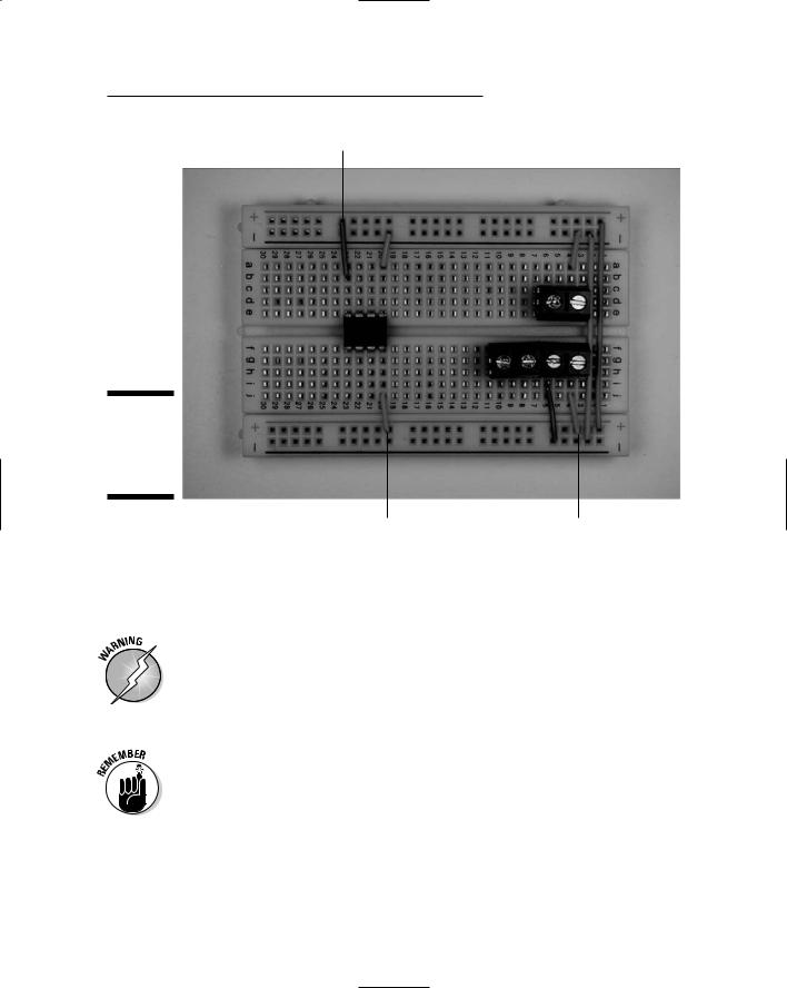
1.Place the LM555 IC and three terminal blocks on a breadboard, as shown in Figure 9-7.
Figure 9-7:
Place the
LM555 IC and terminal blocks on the breadboard.

198 Part III: Let There Be Light
The three terminal blocks shown in this figure will be used to connect two wires each to various components in the circuit. The wires from these terminal blocks go to the battery pack, IR LED, and potentiometer, respectively.
2.Insert wires to connect the IC and the terminal blocks to the ground bus (marked with a – sign on this breadboard) and insert a wire between the two ground buses to connect them to each other, as shown in Figure 9-8.
Three shorter wires connect components to the ground bus; the long wire on the right connects the two ground buses.
Figure 9-8:
Connect components to the ground bus.
3.Insert wires to connect the IC and the terminal block for the battery to the +V bus, as shown in Figure 9-9.
4.Insert wires to connect the IC, terminal blocks, and discrete components, as shown in Figure 9-10.
5.Insert discrete components on the breadboard, as shown in
Figure 9-11.
Note that the shorter of the LED leads is inserted in the ground bus.
Chapter 9: Scary Pumpkins 199
Pin 4 of IC1 to +V
Figure 9-9:
Connect components to the +V bus.
Pin 8 of IC1 to +V |
Battery terminal block to +V |
6.Solder the black wire from a battery snap to one lug of the on/off switch and solder a 5" black wire to the other lug of the on/off switch.
7.Solder two 5" wires to the potentiometer, as shown Figure 9-12.
Be sure to heed all the safety precautions about soldering that we give you in Chapter 2. For example, don’t leave your soldering iron on and unattended. And just in case a bit of solder has an air pocket and pops, wear your safety glasses!
8.Cut the leads of the IR LED to 1⁄4", keeping track of which is the long (+V) lead.
Wear your safety glasses any time you cut wires!
9. Insert the IR LED in the LED socket, making sure that the +V lead is lined up with the white wire from the socket.
Figure 9-13 shows the LED inserted into the socket.