

Electronics_Projects_For_Dummies
.pdf70 Part I: Project Prep
C3 C5 R3 |
C1 |
Battery and S1 TB |
Figure 4-10:
A breadboarded parabolic microphone circuit.
|
|
|
|
|
|
|
|
|
|
|
|
|
C4 |
C2 |
IC1 |
|
|
R1 |
|
||||
|
|
|
|
|
|
|
|
|
|
|
|
Headphone/speaker TB |
|
|
Potentiometer TB |
|
Microphone TB |
||||||
We bent the wires on the ceramic capacitors at a 45° angle so that the face of the capacitor is visible. That way, you can easily read the value of the capacitor on the board.
We cut the leads of the electrolytic capacitors to about 3⁄4" to minimize how far they stick up in the air.
When you use a breadboard, you can use and reuse components for different projects. However, be aware that the little contact wires on components can break off easily. If you remove ICs, use an IC extractor or the flat end of a small screwdriver to pry the IC up at both ends, or you will damage it and probably end up tossing it. The leads on ICs aren’t designed to be bent more than once or twice, or they will break off.
Soldering Your Circuit Board
Electronics projects involve a lot of little bits called components (think transistors and capacitors, for example) and wire, and items like microphones and light bulbs and such. In many instances, you have to solder some of

Chapter 4: Running Down the Skills You Need 71
these things together to provide an electrical connection between them. Solder is a metal material that you melt and apply to two items; when it cools, it forms a joint that holds items together and forms an electrical connection.
So why do you need to solder if you use solderless breadboards? Although we chose to not have you make circuits permanent by soldering them for the purpose of the projects in this book, we do ask you to solder wires to switches and microphones and such, so this is definitely something you need to be able to do.
Soldering perfect joints is an acquired skill — one that you just get better at with practice. Here are some valuable tips for getting started.
Please, please read the several safety precautions about soldering in Chapter 2. You’re playing around with 700°F temperatures here, and we don’t want you to get hurt!
Using a soldering iron
A soldering iron (sometimes called a soldering pencil) is like a wand that gets very, very hot so that when you touch it to the solder, it melts it. You can find a variety of soldering iron models (see an example in Figure 4-11), which will vary in price based on features, such as those we discuss in Chapter 3.
Figure 4-11:
A soldering iron.

72 Part I: Project Prep
When you’re ready to solder, make sure you attach the best tip for the job; a smaller conical or chiseled tip is your best bet. Then, make sure that the soldering iron is firmly seated in its holder. Finally, wait for it to reach the right temperature, somewhere around 700°F. Just touch the end of your solder to the tip, if the solder quickly melts, the iron is hot enough.
Before using a new solder iron — and periodically, as you use your iron — you should tin it (coat the tip with solder):
1.Heat up the iron.
2.Clean the tip by wiping it on a moist sponge.
3.Apply a little bit of solder to the tip.
4.Wipe off any extra solder with a moist sponge.
Working with solder
Solder is a rather soft metal, and the most common type for electronics projects is a 60/40 rosin core. The rosin core contains flux, which cleans the surface of the wires being soldered. This helps the solder stick to the wire surface.
Solder also comes in different diameters. You don’t need super-thick solder for electronics projects. We use 0.032" diameter solder on the projects in this book.
Molten solder sends out fumes that you wouldn’t want your worst enemy to breathe. Lead-free solder helps you avoid toxic lead fumes. Keep your workspace well ventilated no matter what kind of solder you use.
When you solder, you press the cold (solid) solder to a part and then apply heat to a part you want to join, not to the solder itself (see Figure 4-12).
|
Wire between |
|
|
||
Figure 4-12: |
solder and |
|
soldering pencil |
||
In this |
||
Solder |
||
example, |
||
Soldering |
||
apply the |
iron to the |
pencil |
|
|
wire, not |
|
the solder. |
|

Chapter 4: Running Down the Skills You Need 73
When you solder, hold the soldering iron just as you would a pencil (near the base) and be careful to avoid touching the very hot tip. Touch the iron to the elements that will be joined to heat them and then feed solder onto them.
The solder should flow like how water flows around your finger when you hold it under a running faucet.
When you’re done soldering, pull the solder and the iron away, and let the solder cool that you applied. Take a look at the joint you made; it should be shiny and shaped like a little mountain (not a deflated soccer ball).
Here are some tips for good soldering:
Keep it clean. Make sure the parts that you solder are clean and that your soldering iron has a clean, tinned tip.
See the preceding section for the skinny on tinning.
Watch the heat. Be sure to get the soldering iron hot enough and heat any parts you are soldering before you apply the solder.
Easy does it. You should need to hold the soldering iron on a joint only a few seconds.
If you heat a component for longer than a few seconds, you might damage it.
The eyes have it. Always wear safety glasses when soldering.
Pockets in solder could pop when heat is applied. Your eyes are not the place for hot solder to settle.
Keep it clean, Part 2. Keep a damp (not dripping wet) sponge handy to wipe away excess solder on the tip and to wipe the tip clean before soldering each component.
Bend before you solder. Before soldering a wire onto a component, bend the end of the wire in a U shape and insert the U through the hole in the lug you want to solder to. Use a pair of needlenose pliers to clamp the wire to the lug. Then you can solder without having to hold the wire, the solder, and the soldering iron, which is nigh impossible (assuming you have only two hands).
Read about third-hand clamps in the upcoming section, “Soldering extras.”
Figure 4-13 shows a switch and two potentiometers with wires soldered to the component lugs.

74 Part I: Project Prep
Figure 4-13:
Soldering wires to component lugs.
Bend before you solder, Part 2. Before soldering a wire to a component that has presoldered flat contact pads, do the following:
1.Bend the end of the wire at a 45° angle.
2.Heat the end of the wire.
3.Apply a light solder coating to the wire.
4.Press the wire onto the contact pad with the soldering iron.
5.Hold down the wire with the soldering iron until the solder on the pad melts.
6.Remove the iron and hold the wire on the pad with your other hand until the solder cools. (You should hold the wire several inches from
the solder joint so your fingers don’t get hot.)
Make sure that the component you’re soldering is kept steady. (Read about third-hand clamps in the next section for help with this.)
Figure 4-14 shows a microphone cartridge wire soldered with this technique.
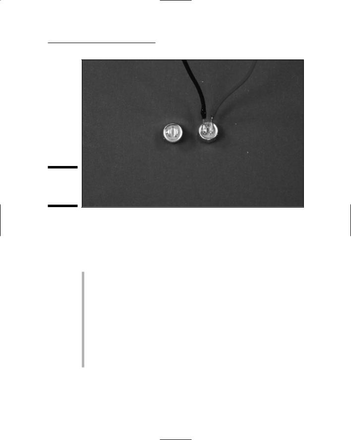
Chapter 4: Running Down the Skills You Need 75
Figure 4-14:
Soldering to flat contact pads.
Soldering extras
Your soldering iron and solder are the main tools you need to make soldered joints. However, a few accessories will make your soldering life easier. These include
Sponge: You use a damp (not dripping) sponge to wipe the tip of your soldering iron clean before soldering each component.
Tip cleaner: If you don’t keep the iron’s tip clean, it might actually repel solder — making it bead up and staying away from where you want it to go. When the tip is too grungy to be cleaned by simply wiping it on the damp sponge, use a tip cleaner paste to chemically clean it.
Solder wick: Sometimes you have to desolder a bad joint and then resolder it. To help remove the bad solder, you can use a solder wick, which is a flat, braided piece of copper that soaks up solder.
Third-hand clamp: There are fancy clamps you can buy called third-hand clamps to hold components while you solder them. Personally, we just use a vice and an alligator clip; they do just fine!

76 Part I: Project Prep
Measuring Stuff with a Multimeter
A multimeter (see Figure 4-15) is a testing device that, um, tests multiple things, including resistance, voltage, and current. Using certain multimeter models, you can test to be sure that components — such as diodes, capacitors, and transistors — function properly. You can also troubleshoot your circuit to see where current is failing and pinpoint the problem spot.
Figure 4-15:
The multifunction multimeter.
You don’t have to break into your piggy bank to buy a multimeter. You can find them for about $10; if you want fancy features, you can spend over $100. Find a model whose price you like and then splurge on the next higher-priced model. You will use a multimeter all the time. Trust us: It’s worth a few extra bucks for a better model. See Chapter 3 for more information about multimeter features.
How a multimeter works
A multimeter has a set of leads: a black one and a red one. You attach these leads to the component or portion of the circuit that you’re testing, and a digital readout provides the results. You adjust a knob to set the test you wish to perform such as resistance, voltage, or current as well as the range to test. Note: Some multimeters have an auto-ranging feature that saves you the trouble of setting the range.

Chapter 4: Running Down the Skills You Need 77
Test leads that typically come with multimeters use simple cone-shaped tips. You can buy test clips that slip onto the cone-shaped tips to make it easier to clip them onto the leads of a component. This makes testing much easier, trust us.
The two things we test most often with our multimeter are resistance and voltage.
Reading resistance
The problem with resistors is that manufacturers seem to expect you to memorize the color code that identifies the resistance rating. Here is an easier way:
1.Clip your test leads onto the resistor leads.
2.Dial your multimeter to the resistance range you think the resistor fits in.
3.Read the value.
If your multimeter reads 1, you guessed too low of a value. Move the dial to the next range up until you get a valid reading. If your multimeter reads at close to 0 (zero), you guessed too high of a value. Dial to the next range down until you get a valid reading; if you get to the lowest range and the value is still 0, whatever you’re testing has zero resistance.
Testing switches or relays is another common use of the resistance-testing feature of your multimeter. You can clip your test leads onto the lugs of an SPST switch to verify that it’s working. (Hint: Occasionally, they don’t work.) When the switch is open, you should get a value of 1, meaning that the resistance is higher than your meter can measure. When the switch is closed, you should get a low resistance — close to 0 (zero) ohms. You can also test SPDT or DPDT switches or relays, like those we use in Chapter 13, to make sure which lugs are connected in which switch position.
Measuring voltage
To run a test to measure voltage, you connect the red multimeter lead to the positive side of the battery or circuit that you’re testing and the black lead to the negative or ground side and set the dial to the voltage range you expect.
We often check the voltage at the contacts of a battery pack. To do this, touch the red lead to one of the battery pack outputs and the black test lead to the other. With a 4-battery pack loaded with fresh batteries, you should get a reading of about 6 volts. (If you get a reading of –6 volts, don’t worry: Just reverse which lead you are touching to which battery pack output.) When batteries

78 Part I: Project Prep
get old, the voltage drops. If you get less than 5 volts from a 4-battery pack, it’s time to get new batteries.
When a circuit doesn’t work, one of the first things to check is the voltage between the +V bus and the ground bus of the breadboard. Here’s how:
1.Strip both ends of a 3" piece of 22 gauge wire.
2.Clip one end of each wire to one of your test leads.
3.Slip the free end of the wire attached to your red test lead into any contact on the +V bus.
4.Slip the free end of the wire attached to your black test lead into any contact on the ground bus.
Although you might not get a reading of the full 6 volts because of drain on the battery from the circuit, you should get a reading above 3.5 volts.
If you get a reading close to 0 (zero) volts, check to make sure that your battery pack and the wires from the battery pack terminal block are connected properly.
Working with the Boxes that
Contain Your Projects
In most cases, you’ll want to put the breadboard on which you build your circuit into some kind of container. A container can make toting around your breadboard easier, help prevent little bits from falling off, and make your project look better. You might also want to add mechanisms for controlling your circuit in a box. For example, you might operate a remote control device by disconnecting and connecting wires on a breadboard, but wouldn’t it be easier to put the breadboard in a box and then add switches and buttons you can use to make it work?
In this section, we give you some advice about basic skills you need to work with these containers for your projects.
Working with boxes
Essentially, using a box involves finding the right type of box and then drilling or cutting holes in it to poke wires and items such as switches or speakers through.

Chapter 4: Running Down the Skills You Need 79
Choosing plastic or wood
You could build your own boxes, but you can find a large variety of containers that you can simply buy cheaply and put right to work, including plastic and wooden boxes in various shapes. We typically put remote control circuits in plastic boxes to make the control light and compact for handling. And we typically use wooden boxes to house other circuits because we can make them look a little more stylish than the plastic boxes.
Drilling and cutting holes
We use a drill to make holes up to 1⁄2" diameter in boxes. There’s nothing complicated about using an electric drill, but if you’re new to this tool, have someone at your local home improvement center walk you through it.
Here’s an easy way to decide what size drill bit to use. Try slipping drill bits through the nut used to secure the screws or electrical component you’re drilling the hole for. Choose a drill bit that’s too big to fit through the hole in the nut and smaller than the outside of the nut.
Drill bits sometimes bind in the material you’re drilling. When a drill bit binds, the box gets kind of edgy and begins to spin with the drill. That’s why it’s important that you clamp the box you’re drilling to your worktable or secure it in a vise. We’ve found that drill bits bind more often in plastic boxes than in wooden ones.
Mounting your project in a box
After you build your circuit and drill or cut holes in your box to accommodate anything you want to feed through from inside to outside, actually mounting things in the box has a few ins and outs, too.
Working with switches, potentiometers, and other panel-mount components
Many switches, potentiometers, and other components have a threaded shaft, a nut, and possibly washers that are meant to be mounted through a hole in a panel. Here’s the drill (pun intended):
1.Drill a hole in your box where you want to mount the component.
2.Clean up any debris around the hole from the drilling.
3.Slide the threaded shaft through the hole and tighten a nut on the threads.
If the hole turns out to be a little too big, slip a washer under the nut.
@Spy