

Electronics_Projects_For_Dummies
.pdf210 Part III: Let There Be Light
Ground pin, use black wire
+V pin, use red wire
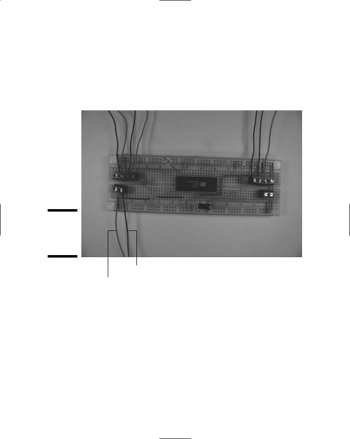
Figure 9-24:
Microphone and IR detector pin identification.
Vout pin, use black wire
Ground pin, use black wire
+V pin, use red wire
Figure 9-25:
Wires soldered to the microphone, IR detector, and record switch.
|
|
|
|
|
|
|
|
Chapter 9: Scary Pumpkins 211 |
||||||
Wire from on/off switch |
|
|||||||||||||
|
|
|
|
|
|
|
|
|||||||
|
|
Red wire from battery pack |
Black wire from ground pin of IR detector |
|||||||||||
|
|
|
|
Wires from speaker |
|
Red wire from IR detector |
|
|||||||
|
|
|
|
|
|
Black wire from Vout pin of IR detector |
|
|
||||||
|
|
|
|
|
|
|
|
|
|
|
|
|
|
|
|
|
|
|
|
|
|
|
|
|
|
|
|
|
|
|
|
|
|
|
|
|
|
|
|
|
|
|
|
|
|
|
|
|
|
|
|
|
|
|
|
|
|
|
|
Figure 9-26:
Attach wires to terminal blocks.
Black wire from microphone
Red wire from microphone
Trying It Out
Those trick-or-treaters are probably lumbering up your street as we speak, so get your pumpkins set up and working to give them a proper scare.
Follow these steps to operate the scary pumpkins:
1.Press the on/off switch of the talking pumpkin to turn it on.
2.Press and hold down the record switch and speak your greeting.
212 Part III: Let There Be Light
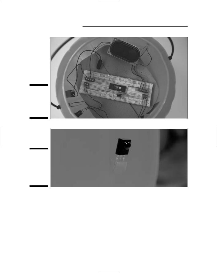
Figure 9-27:
Talking pumpkin with electronics in place.
Figure 9-28:
The IR detector mounted in the side of the pumpkin.
3.Place the talking pumpkin on one side of your entryway (just inside, or safely out of the rain because these are not waterproof) and place the silent pumpkin on the other, with the IR LED facing the IR detector.
4.Flip the on/off switch of the silent pumpkin to On and adjust the potentiometer until the talking pumpkin starts talking.
5.Wait for your guests to walk between the pumpkins, and watch them scatter in fear (or laugh in delight) when the pumpkins sound off.
Chapter 9: Scary Pumpkins 213
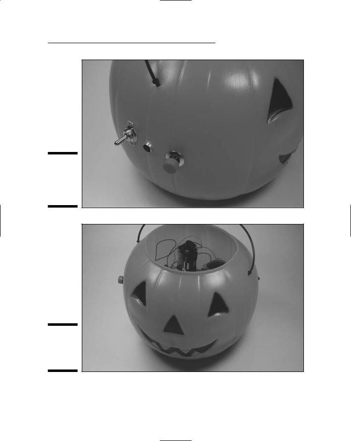
Figure 9-29:
Switches and microphone mounted on pumpkin.
Figure 9-30:
The talking pumpkin, all put together.
214 Part III: Let There Be Light
Here the obvious things to check out if you’re having a problem:
All the batteries are fresh, are tight in the battery pack, and face the right direction.
No bare wires near the microphone or IR detector touch each other.
If you need to troubleshoot your circuit beyond the obvious, here are some options:
See whether the LEDs are inserted backward or are burned out.
If the sound isn’t loud enough, go with a 4 ohm, 1 watt or greater, speaker.
If nothing’s shaking, make sure the IR detector wires are connected to the correct terminal block pins.
Make sure that the IC isn’t backward.
To test that the circuit in the silent pumpkin works, place a standard LED into the circuit instead of an IR LED. If you get a light, try a different IR LED or check the connection to the IR LED.
Taking It Further
Aren’t talking pumpkins just so cool? (Sounds like a rap group, now that we think of it!) You can morph these guys into something else or expand their functionality in a few different ways:
Obviously, you can change the containers for this light and sound event to whatever your heart desires. Plastic Santas, scarecrows, or firecrackers come to mind.
You could have a one-two punch scenario for your pumpkins: One sound goes off when somebody steps into the beam, and another sound hits when somebody steps out of it. You need a receiver and transmitter in each pumpkin. Then connect the signal output of the IR detector to Pin 23 of the voice chip in a receiver circuit in one pumpkin, and Pin 24 of the voice chip in the receiver circuit of the other pumpkin.
Try using a voice synthesizer chip. Instead of recording your own message, buy a voice synthesizer chip, such as the one we use in Chapter 7. This allows you to put together custom sound effects such as a rocket blasting off, a bit of Beethoven’s Ninth Symphony, or a red alert alarm when somebody interrupts your IR beam.

Chapter 10
Dancing Dolphins
In This Chapter
Taking a peek at the schematic
Checking off the parts list
Breadboarding the dolphin circuit
Making dolphins out of lights
Lighting up your dolphins
We all know that lighting effects make for a good time at movie premieres and parties. Building a design from lights and making the lights
move in sequence can give you a great effect.
In this project, we show you how to create a series of dolphins dancing across the water (well, the plywood). You could just as easily create a series of spaceships in sequential stages of taking off, birds flying through the sky, or just about anything you can imagine.
Along the way, you can pick up some tips about timer chips, decade counters, and the artistic opportunity of stringing lots (and we do mean lots) of LEDs in sequence.
The Big Picture: Project Overview
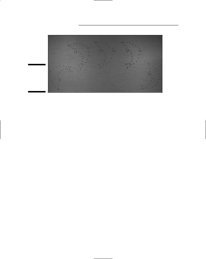
When you complete this project, you’ll have a wall display sporting five dolphins, outlined in LEDs, that light up one after the other, making them seem to dance across the wall. You can see the little guys jumping and jiving in the finished display shown in Figure 10-1.
216 Part III: Let There Be Light
Figure 10-1:
The final product: dancing dolphins.
Here’s the big picture of the dancing dolphin project:
1.Put together an electronic circuit to control the timing of the light display.
2.Create a template for the dolphins and drill holes in a plywood sheet for five dolphin outlines by using the template.
3.Wire five arrays of LEDs and resistors onto the plywood sheet.
4.Mount the circuit on the plywood, connect the arrays of LEDs to the circuit, and add a plywood board to the back of the project.
5.Turn on the juice (that is, pop in the batteries).
The circuit sends current to each group of LEDs for about two seconds, lighting up and then dimming the dolphins in sequence.
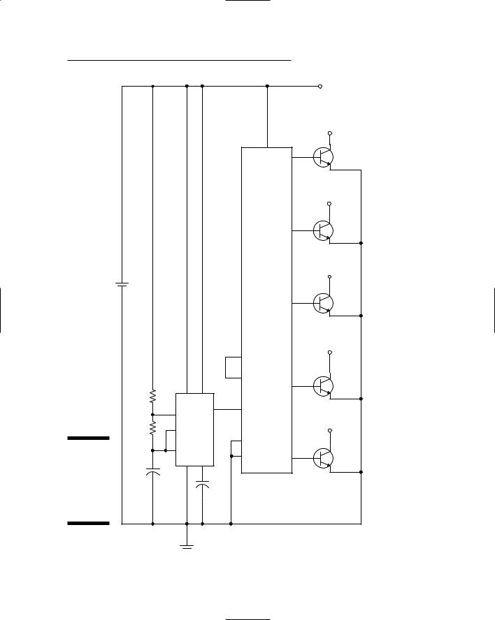
Scoping Out the Schematic
You have but one breadboard to put together for this project, but we make up for that by making you string 5 LED/resistor arrays, each containing 38 LEDs and 19 resistors.
Take a look at the schematic for the board, as shown in Figure 10-2.
Chapter 10: Dancing Dolphins 217
|
|
|
|
|
|
|
|
TO LED |
|
|
|
|
|
|
|
|
ARRAYS 1 TO 5 |
|
|
|
|
|
|
|
|
TO LED ARRAY 5 |
|
|
|
|
|
|
16 |
10 |
Q5 |
|
|
|
|
|
|
|
||
|
|
|
|
|
|
|
|
TO LED ARRAY 4 |
|
|
|
|
|
|
|
7 |
Q4 |
|
|
|
|
|
|
|
|
TO LED ARRAY 3 |
|
+ |
|
|
|
|
|
|
|
|
- 6V |
|
|
|
|
|
|
|
|
|
|
|
|
|
|
4 |
Q3 |
|
|
|
|
|
|
|
|
|
|
|
|
|
|
|
|
|
TO LED ARRAY 2 |
|
|
|
|
|
1 |
|
|
|
|
|
|
|
|
15 |
|
2 |
Q2 |
|
|
|
|
|
|
|
||
|
R1 |
|
8 |
4 |
|
|
|
|
|
|
|
|
|
|
|
||
|
|
|
7 |
3 |
14 |
|
|
|
|
|
|
|
|
|
|
TO LED ARRAY 1 |
|
|
R2 |
|
6 |
|
|
|
|
|
|
|
|
|
|
|
|
||
|
|
|
|
|
|
|
|
|
|
|
|
|
|
13 |
|
|
|
Figure 10-2: |
|
|
2 |
|
8 |
|
3 |
Q1 |
The |
|
|
1 |
5 |
|
|||
|
+ |
|
|
|||||
schematic |
C1 |
|
IC1 |
|
|
|
|
|
|
|
|
|
IC2 |
|
|||
of the |
|
|
|
C2 |
|
|
|
|
dancing |
|
|
|
|
|
|
|
|
|
|
|
|
|
|
|
|
|
dolphin |
|
|
|
|
|
|
|
|
circuit. |
|
|
|
|
|
|
|
|
218 Part III: Let There Be Light
Getting in the swim: Exploring the dolphin circuit
To make your dolphin shapes light up in sequence, you need to make a circuit that uses a timer chip and a decade counter chip in combination with some resistors and a capacitor plus some transistors. Together, these control how often each of the five dolphins lights up and how long each stays lit.
A decade counter essentially takes a square wave and breaks it up into ten pulses. For those of you who took Latin, you’ll recognize decade as related to the magic number ten. Read more about this counter in the following list.
Here’s the overview of the schematic elements that you use to control your terpsichorean dolphins:
IC1 is a key component of this circuit; it’s an LM555 timer chip that you use to generate a square wave at its output on Pin 3.
IC2 is the other key component of this circuit. This is a 4017 decade counter that takes a square wave and generates ten sequential pulse outputs. A 4017 decade counter does this by placing +V on one of its output pins at a time, one after the other. The 4017 decade counter switches to the next output pin at the start of each cycle of the square wave generated by the timer, as shown in Figure 10-3. This allows you to control the rate at which the 4017 decade counter switches +V to each output pin; this is done by controlling the frequency of the square wave generated by the LM555 timer chip. Because we didn’t want ten dolphins, we connected the sixth output pin (Pin 1) to the reset pin (Pin 15). This applies +V to the reset pin after five dolphins dance across the wall and also resets the counter to the first output pin, skipping the last four output pins altogether.
R1, R2, and C1 are, respectively, two resistors and a capacitor that form the RC circuit that determines the frequency of the square wave generated by the LM555 timer chip.
Q1, Q2, Q3, Q4, and Q5 are 2N3053 transistors that turn on when the output pin of the 4017 decade counter they’re connected to is switched to +V. You use these transistors to supply the necessary current — about 190 milliamps — to light the 38 LEDs in each group.
The 555 timer IC generates a square wave from its output. The frequency of the square wave that is generated is determined by how fast the capacitor fills and drains. You calculate how fast the capacitor fills to two-thirds of its capacity or drains to one-third of its capacity by using the RC time constant equation. You can read more about this equation in Chapter 9.
C2 is a capacitor that reduces the occurrence of noise on Pin 5 of the LM555, which could cause false triggering of the IC. This noise can occur if Pin 5 is left unconnected (also called floating).

Chapter 10: Dancing Dolphins 219
|
Square Wave |
|
|
|
|
|
|
|
|
|
|
|
|
|
|
|
|
|
|
|
|
|
|
|
|
|
|
Pin 3 |
|
|
|
|
|
|
|
|
|
|
|
|
|
|
|
||||||||||
|
|
|
|
|
|
|
|
|
|
|
|
|
|
|
|
|||||||||||
|
Pin 2 |
|
|
|
|
|
|
|
|
|
|
|
|
|
|
|||||||||||
|
|
|
|
|
|
|
|
|
|
|
|
|
|
|
|
|
||||||||||
|
|
|
|
|
|
|
|
|
|
|
|
|
|
|
|
|
|
|
|
|
|
|
|
|
|
|
|
|
|
|
|
|
|
|
|
|
|
|
|
|
|
|
|
|
|
|
|
|
|
|
|
|
|
Figure 10-3: |
|
|
|
|
|
|
|
|
|
|
|
|
|
|
|
|
|
|
|
|
|
|
|
|
|
|
|
|
|
|
|
|
|
|
|
|
|
|
|
|
|
|
|
|
|
|
|
|
|
|
|
|
|
You put in |
Pin 4 |
|
|
|
|
|
|
|
|
|
|
|
|
|||||||||||||
|
|
|
|
|
|
|
|
|
||||||||||||||||||
one square |
|
|
|
|
|
|
|
|
|
|
|
|
|
|
|
|
|
|
|
|
|
|
|
|
|
|
wave to get |
|
|
|
|
|
|
|
|
|
|
|
|
|
|
|
|
|
|
|
|
|
|
|
|
|
|
out multiple |
Pin 7 |
|
|
|
|
|
|
|
|
|
|
|||||||||||||||
|
|
|
|
|
||||||||||||||||||||||
sequential |
|
|
|
|
|
|
|
|
|
|
|
|
|
|
|
|
|
|
|
|
|
|
|
|
|
|
little pulses. |
|
|
|
|
|
|
|
|
|
|
|
|
|
|
|
|
|
|
|
|
|
|
|
|
|
|
|
Pin 10 |
|
|
|
|
|
|
|||||||||||||||||||
|
Setting up the light show |
|||||||||||||||||||||||||
|
The circuit won’t mean a thing if you don’t set up the lights for it to control. |
|||||||||||||||||||||||||
|
That’s where the elements of the LED/resistor arrays come in. An array, in |
|||||||||||||||||||||||||
|
this case, equals the lights that define one whole dolphin. |
|||||||||||||||||||||||||
|
These five arrays each include |
|||||||||||||||||||||||||
|
38 LEDs, which light up when a river of current runs through them |
|||||||||||||||||||||||||
|
19 resistors, which are resistors that limit the current running through |
|||||||||||||||||||||||||
|
the LEDs in series with each resistor to approximately 10 milliamps |
|||||||||||||||||||||||||
|
Take a look at the schematic for these in Figure 10-4. Notice that we have not |
|||||||||||||||||||||||||
|
assigned a number to each LED and resistor. That is because we have 190 |
|||||||||||||||||||||||||
|
LEDs and 95 resistors among the 5 dolphins — and we don’t have time. |
|||||||||||||||||||||||||
|
These LEDs and resistors are wired together such that two LEDs and one |
|||||||||||||||||||||||||
|
resistor are in series. When +V is applied, current runs through each compo- |
|||||||||||||||||||||||||
|
nent sequentially. Each group of two LEDs and one resistor are connected |
|||||||||||||||||||||||||
|
parallel with the other groups of LEDs and resistor. Because 19 LED/resistor |
|||||||||||||||||||||||||
|
groups are in each array, the total current running through an array is |
|||||||||||||||||||||||||
|
approximately 190 milliamps. |
|||||||||||||||||||||||||