

Electronics_Projects_For_Dummies
.pdf50 Part I: Project Prep
Let there be light: Light emitting diodes
A diode sends out light when you pass an electric current through it. LEDs, which we use quite a bit in the projects in this book, are similar to the tiny, twinkly lights you use to decorate a Christmas tree, and they come in a variety of colors, such as red, orange, yellow, green, blue, and white. Blue and white LEDs are a lot more expensive, so you don’t see them used that often in this book. (We’re thrifty!)
LED color isn’t controlled by the plastic that surrounds the light. Rather, the semiconductor material used in the LED determines the color. The plastic surrounding the semiconductor material can be clear or treated so that it diffuses the light.
In addition, you can get LEDs in several sizes and shapes. The standard LED, which is a cylinder with a diameter of 5mm, is referred to as T-1 3⁄4.
If you don’t connect LEDs the right way, you could wait forever to see the light. Connect the longer of the two leads to the positive voltage and the shorter of the two leads to ground or the more negative voltage.
Speaking up about speakers
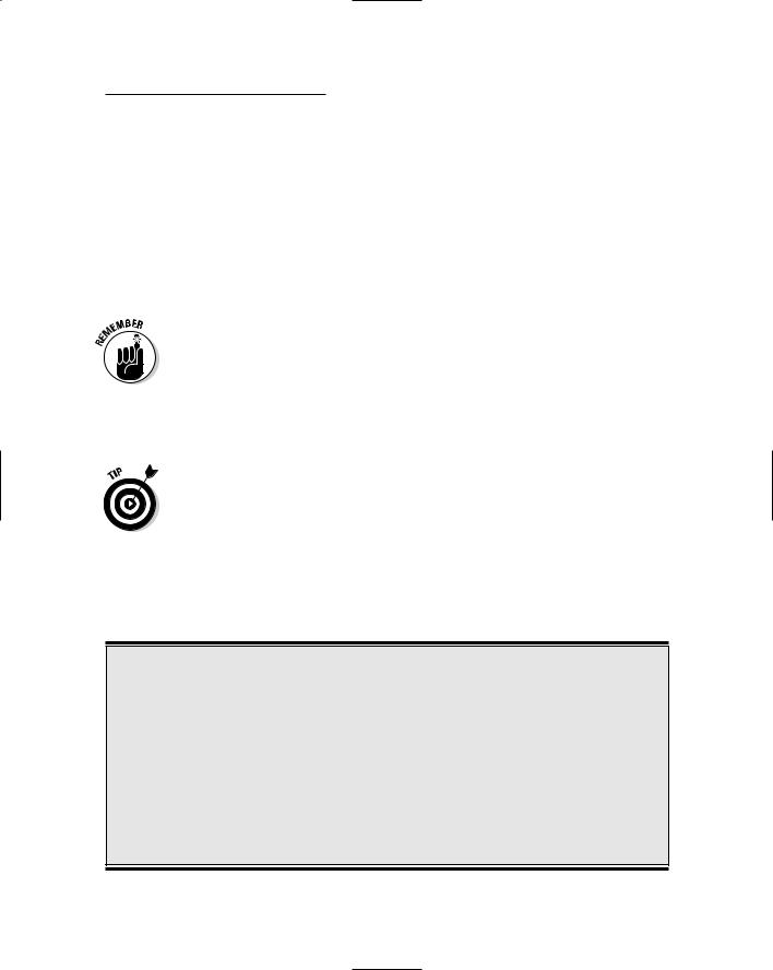
Everybody knows what a speaker is: There’s one on your DVD player, your computer, your iPod — you name it! Most speakers contain a permanent magnet, an electromagnet, and a cone-shaped device from which the sounds emerge (see Figure 3-9).
Cone
Permanent magnet
Figure 3-9:
The parts that make up a speaker.
Electromagnet

Chapter 3: Assembling Your Electronics Arsenal |
51 |
When current moves through the electromagnet, which is attached to the cone, it gets pushed toward or pulled away from the permanent magnet. This depends on which way the electric current is moving. This movement of the electromagnet is what makes the cone vibrate, and that produces sound waves.
Speakers come with a rated impedance (the degree to which a component resists electrical current): for example, 4 ohm, 8 ohm, 16 ohm, or 32 ohm. A speaker is often referred to by its impedance: for example, “I’m going out to buy an 8 ohm speaker.” When you use a speaker in a circuit, it should have an impedance rating that matches the minimum impedance rating that the amplifier hooked up to the speaker can drive. If you use a speaker with higher impedance than the amplifier can drive, you won’t get the maximum amount of sound; conversely, if you use a speaker with lower impedance than the amplifier can drive, you might overheat the amplifier. You can find this rating in the datasheet on your supplier’s Web site.
For example, in Chapter 8, we use an 8 ohm speaker because the LM386 amplifier can drive a speaker with impedance as low as 8 ohms. And in Chapter 14, we use a 16 ohm speaker because the ISD1110 voice record/ playback chip can drive a speaker with impedance as low as 16 ohms.
Speakers also come with a power rating, such as 0.2 watt, 1 watt, or 2 watt. Choose a speaker with at least as high of a power rating as the maximum output of the amplifier. Again, you can find this maximum output in the amplifier datasheet.
When you buy a speaker for electronics projects, buy one that comes with convenient holes in the corners of metal or plastic flanges that you can slip screws through. These help you to easily attach the speaker to the box you’re putting the circuit in. See Chapter 4 for more about building and assembling projects.
Buzzers
If you have an annoying friend who plays practical jokes, you’ve probably been on the receiving end of the buzzer and handshake joke. A buzzer essentially generates a sound, which you can use in projects in a variety of ways. For example, a buzzer could be the horn on a remote controlled car or an alarm that goes off when a sensor detects motion.
In a buzzer, you apply voltage to a crystal (a piezoelectric crystal), which then expands or contracts. By attaching a diaphragm to the crystal, you cause the diaphragm to vibrate when you change the voltage. This vibration causes that bzzz sound. There are electromagnet buzzers, but the piezo buzzer works just fine for electronic projects, so we stick to using them in this book.

52 Part I: Project Prep
Most buzzers give off sound in the 2–4 kHz range. Buzzers aren’t very discriminating when it comes to voltage: Their ratings are approximate, meaning that a 12V buzzer is absolutely happy to work with a 9V power supply.
Buzzers have two leads, and you have to connect a buzzers the right way round. The red lead is always positive (+).
The Nuts and Bolts of Building Materials
A pure electronics project might just consist of a breadboard containing components and wires. In most cases, though, you’ll also want to create some sort of container or chassis to hold the project. For example, if you build a simple radio, you might put the guts of it in a box and drill holes to place the dials and speaker.
You can buy ready-made boxes or other containers and make them work for your project. You can also build your own out of various materials.
Plastic
ABS (please don’t ask what this acronym means; we could tell you, but you couldn’t pronounce it) plastic boxes are available from most electronics suppliers. These are lightweight, sturdy, waterproof, and handy for housing your gadgets. We use a plastic box in Chapter 11 to house a remote control.
The plus with plastic boxes is that components such as switches are designed to be mounted on boxes or panels with thin walls. Therefore, mounting these components on these plastic boxes is often easier than on wooden boxes.
The downside is that cutting clean openings in plastic is harder than in wood — for example, to insert speakers.
Wood
We like to use wooden boxes to house many of our projects because, well, they look nice. We found simple, unfinished wooden boxes at a national craft supply superstore (Michaels), but any craft store probably stocks them.

Chapter 3: Assembling Your Electronics Arsenal |
53 |
Wood is also easier to drill and cut than plastic; however, you’ll often find that the wall of the box is 1⁄4" thick, which makes mounting components such as switches more complicated. In Chapter 4, we provide some advice on how to handle mounting components on wood.
Build it yourself
If you don’t like to buy ready-made containers, you can make your own boxes from wood or plastic. You can easily find lots of books that tell you how to make all sorts of things from wood, so we don’t get into that. To start, you might check out the Woodbox.com Web site and click the Wooden Box Making link for a good overview.
If you want to make your own boxes or build fancier shapes out of plastic, such as a model car, to mount your electronics, check out
www.talkingelectronics.com/Projects/Boxes/BJones-BoxArticle.html
This article is a nice introduction to making custom plastic boxes for electronics projects.
For some projects, you will mount boxes on a base or sandwich them between two sheets of materials. We used sheets of PVC and plywood in our projects. Quarter-inch or 6 mm thickness is a good bet for a strong base. You can use thinner sheets — for example, 1⁄8" or 3 mm — when you don’t need structural strength. Rigid, expanded PVC is often used instead of other plastics because it resists the buildup of electric charges, which might cause electrostatic discharge, which can zap your electronics components.
Robot supply houses, such as Solarbotics (www.solarbotics.com) or Budget Robotics (www.budgetrobotics.com), carry PVC sheeting. At Solarbotics, this material is sold under the product name Sintra. You can find plastics suppliers that sell rigid expanded PVC in 4' x 8' sheets, which is economical if you plan to use a lot of it.
Holding it all together
Sticking materials together to form boxes or whatever can be done in a few different ways.
You can attach many different types of materials together with glue. Look for a glue called contact cement. This can bind a wealth of materials, including metal, plastic, rubber, and wood.

54 Part I: Project Prep
To mount components such as speakers, you need screws and nuts. The parts lists in our project chapters tell you what size screws and nuts to get; we’re betting you have some of these in that leftover cake tin in your garage gathering dust, but you can buy what you need for pennies in any hardware store.
We find that 6-32 screws fit many mounting holes.
Holding down wires
Wire clips are very useful for organizing wires that you affix to your project container. These generally have an adhesive backing on the base that you use to attach them to a surface. Then you slip the wires into the clip, and they are nicely held in place. (We use RadioShack part #287-1668.)
Cable ties can also be useful when you want to run wires along something without a flat surface, like a wooden dowel.
Breadboard Basics
A breadboard is a rectangular plastic box filled with holes, which have contacts in which you can insert electronic components and wires. A breadboard is what you use to string together a temporary version of your circuit. You don’t have to solder wires or anything else; instead, you poke your components and wires into the little contact holes arranged in rows and connected by lines of metal; then you can connect your components together with wires to form your circuit.
The nice thing about breadboards is that you can change your mind and replace or rearrange components as you like. You typically create an electronics project on a breadboard to make sure that everything works. If it’s a project you wish to save, you can create a more permanent version. We use breadboarded versions of circuits exclusively in this book.
If you want to create a permanent version of your circuit, you need to create a soldered or printed circuit board; see the sidebar, “Printed circuit boards,” to find out how to go about that.
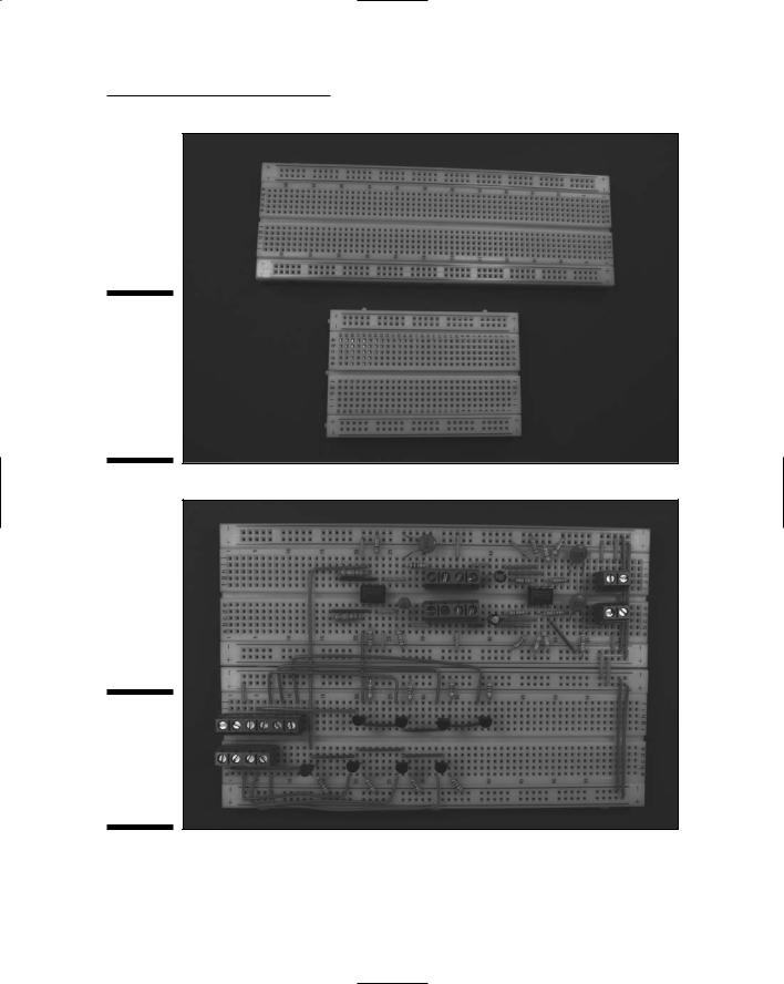
There are a few different sizes of breadboards, some of which are shown in Figure 3-10. You can link breadboards to make a larger circuit, like the one shown in Figure 3-11. See Chapter 4 for more about how to build a breadboard.
Chapter 3: Assembling Your Electronics Arsenal |
55 |
Figure 3-10:
Two breadboards, one with 830 contact holes and one with 400 contact holes.
Figure 3-11:
A large circuit built on multiple breadboards hooked together.
56 Part I: Project Prep
Printed circuit boards
If you create a circuit on a breadboard and decide that it’s worthy of immortality, you can make it permanent by soldering components in place on a printed circuit board. To do this, you have to get your hands on a universal printed circuit board. This is much like a breadboard except that you can solder all the connections you’ve made to keep them around.
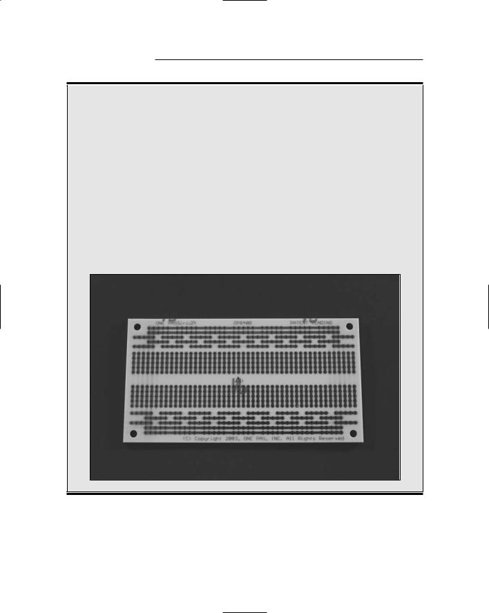
A universal printed circuit board has rows of individual holes throughout the board with copper pads around each hole and metal lines connecting the holes in each row, like in a breadboard. You mount parts on the face of the board and then pass leads through holes to the
components. You can solder the leads to the copper pads on the bottom of the board. Universal printed circuit boards are available in a variety of patterns of contact holes and metal lines. The figure here shows one we like because there are rows on either side that accommodate discrete components handily. This circuit board is made by One Pass, Inc. (www.onepassinc.com).
You can get custom printed circuit boards made for your circuit; this is typically done by submitting a drawing of your circuit to a printed circuit board company. These boards eliminate the need to solder jumper wires between components.
Wires pull it all together
When you place components in a breadboard, you don’t get much action until you connect those components with wire. Wire used in electronics is copper
Chapter 3: Assembling Your Electronics Arsenal |
57 |
surrounded by a plastic insulator, usually called hookup wire. Hookup wire comes in various diameters referred to as a gauge. The standard gauge measurement used in the U.S. is American Wire Gauge, also referred to as AWG. We generally use 22 gauge or 20 gauge wire.
Someone decided at some point that the smaller the gauge, the larger the diameter of wire. For example, 20 gauge wire is 0.032" in diameter, and 22 gauge wire is 0.025" in diameter. Don’t ask us why — just memorize this fact!
We use 22 gauge solid wire for most of the projects in this book. (Okay, in two chapters, we use 20 gauge; and in one, we use 26 gauge, but you’ll find out why when you get to those projects.)
Use solid wire — never stranded wire — between components within a breadboard because stranded tends to separate when you try to insert it into the holes of a breadboard.
You can buy hookup wire in spools; we generally get spools containing 100 feet of wire. If you are starting with only a few projects, you can get smaller spools containing as little as 30 feet of wire.
The insulating plastic that surrounds wire is made in different colors. Pick up a spool of red and a spool of black. Using different colors helps you to identify the purpose of different wires in your project.
You might also consider buying an assortment of different lengths of prestripped and prebent 22 gauge wire jumpers. Jumper wires — which are used to connect components in a breadboard — save you a lot of time you might otherwise spend cutting small wires to length, stripping them, and bending the stripped wire when you’re building a breadboard.
Insulating those naked wires
You will also use various materials to insulate bare wires. You can use electrical tape, for example, to insulate solder joints that might touch each other and cause a short.
Heat shrink tubing is a tidy way to insulate the point where wires connect in a solder joint. Heat shrink tubing is simply a plastic tube. When you slip a short length of this tubing over a solder joint and apply heat, the plastic tube
shrinks, providing an insulating layer around the wire. When working with 22 gauge wire, we use 3⁄32" heat shrink tubing.
Liquid electrical tape is also handy to insulate bare wire in situations where heat shrink tubing or conventional electrical tape doesn’t work very well. We use liquid electrical tape in Chapters 5 and 10, for example.

58 Part I: Project Prep
Connectors
Finally, terminal blocks are used to connect wires from components such as speakers, motors, and microphones to the breadboard. A terminal block is a small block of plastic that you mount on a breadboard. You insert the wires into the terminal block through a hole in the block and then tighten screws to hold the wire securely.
When choosing terminal blocks, the diameter of the pin that inserts into the breadboard or circuit board is important. Some terminal blocks that work fine in circuit boards where the components are soldered in do not stay in place on breadboards. We have had the most success with RadioShack part #276-1388.

Chapter 4
Running Down the
Skills You Need
In This Chapter
Discovering schematics
Assembling little bits and pieces on breadboards
Spiffing up your soldering skills
Troubleshooting problems with a multimeter
Working with the boxes that enclose your projects
You need three key things to build an electronics project: materials, a workspace, and certain skills that help you assemble the materials into
something that moves, beeps, lights up, or otherwise makes itself electronically known to the world. (You also need time, but we’ll leave that to you to find.)
In Chapter 3, we talk about organizing your materials and workspace. In this chapter, we address the third element — the skills that you need to read circuit designs, build, and test electronics projects. This chapter provides an overview of these skills; for more comprehensive explanations, check out Electronics For Dummies, by Gordon McComb and Earl Boysen (Wiley).
It’s Symbolic: Reading a Schematic
A schematic is your blueprint for building an electronics project. A blueprint for building a house uses various symbols to represent elements, such as doors, and lines to show walls. Instead of doors and walls, the symbols and lines in a schematic represent components such as transistors, integrated circuits (ICs), and resistors as well as the wires that connect them.
Be sure to check out the Cheat Sheet (the yellow page at the front of this book) for a table of commonly used schematic symbols.