

Kluwer - Handbook of Biomedical Image Analysis Vol
.3.pdfThree-Dimensional Registration Methods |
117 |
Figure 3.7: The effect of image cropping on registration accuracy. The light and dark bars are RMS distances between bony landmarks with and without image cropping, respectively, as defined in Methods. Conditions on the x-axis are described in Methods.
Displacements of bony landmarks might significantly overestimate the change near the prostate. Hence, as described in section 3.3, we investigated the displacement of voxels in a ROI surrounding the prostate between registrations with and without cropping. For 9 of 10 analyzed volume pairs, the average voxel displacement was <0.5 mm indicating that prostate registration is fairly insensitive to cropping. However, for V3 treatment-reference, a much larger voxel displacement of 7.4 mm was obtained indicating that cropping is critical for this volume pair.
3.2.4.6 Implementation Issues
The algorithm was quite robust and always gave very nearly the same transformation parameters (less than 0.01 voxels and 0.01◦) for the 22 volume pairs in this study using a wide variety of initial guesses. The restarting and multiresolution features are important, and we report some results for a typical volume pair
118 |
Fei, Suri, and Wilson |
registration. The multiresolution approach enabled the program to get close to the final value quickly because of the reduced number of calculations. That is, the time for reformatting at the lowest resolution (1/4) was 9.8 sec, which was less than 1/59 times that at the highest resolution, a value nearly equal to the 1/64 expected from the change in the number of voxels. The number of restarts was 5, 1, and 1 for resolutions at 1/4, 1/2, and the full number of voxels. Each call to the simplex optimization resulted in 55 to 94 MI evaluations before the tolerance (0.001) was reached. The simplex optimization method worked about 1.5–2.0 times faster than the Powell method in our implementation. The time for registration using Simplex, typically 5 minutes on a Pentium IV, 1.8GHz CPU, with 1GB of memory, could probably be greatly improved with optimized C code rather than IDL.
3.2.5 Discussion
3.2.5.1 Registration Accuracy
Our results suggest that MI can be used to accurately register, with an error on the order of a voxel, MR pelvic images obtained under similar conditions. Because it gives an independent, true 3D measurement, we like to use the method of point bony landmarks to assess accuracy. However, as argued in section 3.2.4.3, the true MI registration accuracy might be better than our ability to measure it with point bony landmarks. That is, following point landmark registration, the distance between registered, corresponding landmarks was on the order of that following MI registration. Very possibly, MI is more accurate than point registration using bony landmarks. Additional, independent evidence of excellent MI accuracy comes from the very low error value from the registration consistency measurement (0.6 ± 0.2 mm). Interestingly, this is obtained even though the interpolation artifact present in MI similarity surfaces should reduce the likelihood of subvoxel accuracy [30]. Our results for the pelvis with image volumes obtained under the same conditions compare favorably with those for the brain, where MI registers images very accurately giving errors as small as 0.7–0.8 mm for CT-MR [31].
Visual and quantitative evaluation of prostate organ movement showed good registration even when we acquired images under conditions that greatly stressed the ability to register the images. The small prostate displacements in
Three-Dimensional Registration Methods |
119 |
our study are consistent with earlier reports on respiration-induced prostate movement of ≤1 mm for most patients in supine position with “quiet” respiration [32]. The difference between the treatment and diagnostic positions resulted in the most consistent and largest displacement of the prostate. When images were acquired in the diagnostic position one week apart, there was significant displacement of the prostate due to a change in rectal filling. This is consistent with previously reported results [8, 14], which found rectal filling to be a significant factor in prostate displacement.
There are ways to limit the small displacements of the prostate. One obvious remedy is to acquire images in the same position. That is, if we want to register an image with one obtained in the treatment position, we should obtain it in the treatment position. Although it is unknown how accurately one must repeat the treatment position, a device to support and constrain the legs is probably required. In addition, there is a dependence of registration error on bladder and rectum content. One solution is use clinical preparations often employed to void the bladder and rectum prior to prostate imaging or therapy. We anticipate that this might even lessen prostate displacements between the diagnostic and treatment positions.
We must consider our results with regard to potential applications such as those described in section 3.1. First, registered images acquired before and immediately after treatment can be used to determine whether a tumor is adequately treated. Second, serial examinations can be registered to determine tumor progression or regression. Third, registration of functional images from other modalities such as nuclear medicine or from MR spectroscopy can give molecular markers for prostate cancer [33, 34]. Fourth, we want to register high quality MR images with a few live-time interventional MR images to aid treatment decisions [4, 5]. Our results indicate that registering images from the treatment and diagnostic positions can lead to errors, and potential steps are described above to limit this error. With images acquired in the same position, our results place a lower limit on registration error of about 1 voxel.
3.2.5.2 Assessment of Registration
We are involved in a long-term effort to use registration for detection, assessment, and therapy of prostate cancer. Hence, we have developed and used several methods to assess pelvic and prostate registration.
120 |
Fei, Suri, and Wilson |
It is highly desirable to have an automatic method for evaluating the quality of a registration so that a poor one can be flagged before it is used clinically. The correlation coefficient would be applicable whenever one uses MR images obtained with identical pulse sequences. It compares favorably with the bony landmark results. Registration consistency provides an additional means to evaluate registration accuracy that does not rely on operator interaction.
Other evaluation methods are applicable for clinical or research applications. RegViz provided visual inspection tools for quick evaluation of the quality of registration and potential prostate displacement. Such methods can be used to verify the quality of registration and possibly account for small displacements in some applications. Boundary overlays provide a good means to evaluate organ deformation as well as displacement. Point anatomical landmarks provide a useful, independent test, but it is time consuming to identify them and MI might be more accurate than the point landmarks. Centroids are obtained reliably because small segmentation errors are removed by integrating over the entire prostate volume. Centroids provide a good means of quantifying prostate displacements.
3.2.5.3 Algorithm with Combined Similarity Measures
Using both CC and MI at different resolutions was an important feature that increased robustness. When only mutual information was used, registrations at low resolution sometimes gave false solutions that mislead registration at the next higher resolution. However, CC performed well and gave many fewer local maximums at the lower resolutions (Figs. 3.1a and 3.1b). But MI gave a more accurate solution at the full resolution due to the peaked MI surface (Figs. 3.1c and 3.1d). Our registration algorithm combined advantages from the two similarity measures.
There are probably several reasons why mutual information does not work well at low resolution. First, the similarity curve is noisy with periodic oscillations from the so-called interpolation artifact [30] that is accentuated at reduced resolutions [35]. This results in the many local maximums in Fig. 3.1a that can trap the optimization. A similar result was reported for brain registration [19, 36]. Second, when images are of low resolution and there is only a small region of overlap, the mutual information function can even contain incorrect global maximums [35]. Such a result was found in Fig. 3.1a where the global maximum
Three-Dimensional Registration Methods |
121 |
was obtained at very large displacements where the overlap was reduced. This occurs because MI is not only a function of how well the images match in the overlap, but also by how much information is provided by the two images in the overlap [37].
3.2.5.4 Computer Implementation
Accuracy is an important issue for automatic registration, but there are others such as robustness, speed, and requirements for operator interaction. With the multiresolution and restarting features, our modified MI algorithm is quite robust. For a wide range of initial guesses, it worked well for all 22 volume pairs reported here. Three of the volume pairs were from patients, and we are confident that routinely acquired clinical images will have sufficient quality for registration. Because good starting values are unimportant, operator interaction is minimal. In one instance, cropping of the legs was important for registering an image volume obtained in the treatment position with that in the diagnostic position. It is not surprising that legs in a very different position have to be cropped. Although this is easy to do manually, we can probably determine an automated method if it is deemed desirable.
The mutual information similarity measure is quite robust. Even though our images are very similar, we had less success with some other measures such as the sum of the squared image difference. An advantage of MI is that it can be used with images from different modalities, a feature that we are starting to use.
3.3Three-Dimensional Non-Rigid Body Registration Algorithm
3.3.1 Why Non-Rigid Registration
In the previous section, we discussed rigid body registration of the prostate. For volume pairs acquired over a short time span from a supine subject with legs flat on the table, registration accuracy of both prostate centroids (typically <1 mm) and bony landmarks (average 1.6 mm) was on the order of a voxel (≈1.4 mm).
122 |
Fei, Suri, and Wilson |
We obtained somewhat larger prostate registration errors of about 3.0 mm when volume pairs were obtained under very different conditions, e.g., legs flat and legs raised, or with and without bladder or rectal filling. Rigid body registration of the pelvis cannot follow prostate movements due to changes in the postures of legs and deformation of the bladder and rectum [8]. In this section, we discuss the ability of non-rigid registration to express this deformation.
Non rigid registration studies are reported for the brain [38, 39], for the breast [40, 41, 41, 42, 42], for a variety of other organs [23, 43, 45], and for excised tissue [46]. Far few reports described results of the pelvis and prostate. Bharaha et al. reported a method using manually segmented prostate for rigid body registration followed by finite element-based warping in the application of prostate brachytherapy [47]. Voxel based methods, particularly those based upon mutual information, are robust, require no segmentation that can be prone to error, are highly accurate for brain registration [31], and are suitable for abdominal registration where there can be deformation [20]. We are discussing voxel-based non-rigid registration for the particular application in the pelvis and prostate.
In this section, we perform experiments to compare non-rigid and rigid body registration for the prostate and pelvis. By using high-resolution MR images giving distinctive anatomic detail, we test the ability of a non-rigid algorithm to correct anatomical variations throughout the pelvic region. We include conditions with very significant changes in posture possible in interventional applications, that is, we attempt to register image volumes from a diagnostic scan with legs flat to those from a treatment acquisition with legs raised. We qualitatively and quantitatively evaluated registration results using 17 volume pairs from three volunteers.
3.3.2 Non-Rigid Registration Algorithm
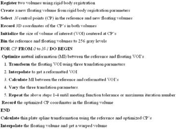
Figure 3.8 outlines the non-rigid registration algorithm that includes three major steps: control point selection, control point optimization, and thin plate spline warping. Prior to non-rigid registration, we perform rigid body registration as reported in Section 3.2. Again, the unchanging volume is the reference, and the one to be warped is floating.
The manual selection of CP’s is an important step. We used RegViz for visualizing and analyzing image volumes. Following rigid body registration, the
Three-Dimensional Registration Methods |
123 |
Figure 3.8: Flow chart of the warping registration algorithm. Following rigid body registration, N control points are selected in both the reference and floating volumes. A small cubic volume of interest (VOI) is centered on each control point. Optimization is performed by varying the x, y, and z locations of the floating VOI until the mutual information between corresponding voxels is maximized. Each control point is optimized independently, and then the optimized control points are used to establish a three-dimensional thin plate spline transformation for the entire volume.
aligned two volumes are displayed in two rows slice-by-slice. Images can be transverse, coronal, or sagittal slices. It is quite straightforward to find corresponding features at the pelvis, prostate, bladder, and rectum. We normally select control points (CPs) using recognizable organ features such as corners and intersections of edges because of their unique positions. Corresponding CPs in the two volumes are placed using a cursor, and sometimes they are in different image slices. The 3D coordinates are automatically stored in a file. Because of the optimization that occurs later, the correspondence can be up to 15 mm or ≈10 voxels in error. Experiences with CP selection are described in Section 3.3.4.4. Typically, we used 180 CPs for a volume with 256 × 256 × 140 isotropic voxels.
The next step of the non-rigid algorithm (Fig. 3.8) is the CP optimization. We define a small cubic volume of interest (VOI) centered at each CP. The VOI
124 Fei, Suri, and Wilson
can be 16, 32, 48 or 64 voxels on a side. As reported later, the selection of the VOI size depends on the amount of warping required. A simplex optimization algorithm varies the x, y, and z transformation parameters of the floating VOI until the mutual information with the reference VOI is optimized. Each control point is optimized independently and the 3D coordinates of the optimal CPs are recorded.
The final major step is to warp the floating volume using the corresponding optimal CPs coordinates to establish a three-dimensional thin-plate spline (TPS) transformation [48, 49]. We now briefly go through the three computing steps
for the TPS transformation.
First, let P1 = (x1, y1, z1), P2 = (x2, y2, z2), . . . , Pn = (xn, yn, zn) be n control
points in the image coordinate of the reference volume. Write r |
|
P |
|
for |
||||||||||
the distance between point i and j. We define matrices: |
ij = |
i − Pj |
|
|||||||||||
|
|
|
|
|
|
|
|
|
|
|
|
|
|
|
|
|
1 |
x1 |
y1 |
z1 |
|
|
|
|
|
|
|
||
|
|
|
|
|
|
|
|
|
|
|
||||
|
P = |
· · · |
· · · |
· · · |
· · · |
|
n × 4; |
|
|
|
|
|
||
|
|
1 |
x2 |
y2 |
z2 |
|
, |
|
|
|
|
|
||
|
|
|
|
|
|
|
|
|
|
|
|
|
|
|
|
|
|
|
|
|
|
|
|
|
|
|
|
|
|
|
|
|
1 |
xn |
yn |
zn |
|
|
|
|
|
|
|
|
|
0 |
|
r12 |
r13 |
|
r1n |
|
|
|
|
|
|
|
|
K = |
|
|
· · · |
· · · |
· · · |
· · · |
, |
n × n; |
|
|
|
|
|
|
|
· · · |
|
· · · |
|
|
|
|
|
|
|
|
|||
|
r21 |
|
0 r23 |
· · · |
r2n |
|
|
|
|
|
|
|
|
|
|
|
|
|
|
|
|
|
|
|
|
|
|
|
|
|
|
|
rn2 |
rn3 |
· · · |
|
|
|
|
|
|
|
|
|
|
rn1 |
|
|
0 |
|
|
|
|
|
|
|
|||
and
L = |
K |
P |
, (n + 4) × (n + 4); |
P T |
O |
where T is the matrix transpose operator and O is a 4 × 4 matrix of zero. Second, let Q1 = (u1, v1, w1), Q2 = (u2, v2, w2), . . . , Qn = (un, vn, wn) be n
corresponding control points in the image coordinate of the floating volume. We get matrices:
|
= |
|
u1 |
u2 |
· · · |
un |
|
|
|
× |
|
V |
w1 |
w2 |
· · · |
wn |
, |
3 |
n, |
||||
|
|
|
|
|
· · · |
|
|
|
|
|
|
T
Y = V | 0 0 0 0 , 3 × (n + 4),
Three-Dimensional Registration Methods |
125 |
and define the vector W = (w1, w2, . . . , wn) and the coefficients α1, αx, αy, and
αz by the equation
L−1Y = (W | α1 αu αv αw )T .
Third, use the elements of L−1Y to define a function f (u , v , w ) everywhere in the entire volume:
n
f (u , v , w ) = α1 + αuu + αv v + αw w + wi |Pi − (u, v, w)|.
i=0
Thus, any voxel (ui, vi, wi) in the floating volume is transformed to a new coordinate (ui, vi, wi) and a warped volume can be obtained by trilinear interpolation.
Additional algorithm details are now described. For both VOI optimization and rigid body registration, we use trilinear interpolation. Optimization of similarity ends either when the maximum number of calculations is reached (typically 500) or the fractional change in the similarity function is smaller than a tolerance (typically 0.001). We use IDL as the programming language.
3.3.3 Registration Evaluation
We used the multiple visualization features of RegViz to visually evaluate registration results. First, we manually segmented prostate boundaries in image slices and copied them to corresponding slices from the other volume. This enabled visual determination of the overlap of prostate boundaries over the entire volume. We applied the same method to evaluate pelvic registration. Second, color overlay displays were used to evaluate overlap of structures. One image was rendered in gray and the other in the “hot-iron” color scheme available in IDL. To visualize potential differences, it was quite useful to interactively change the contribution of each image using the transparency scale. Third, we used a sector display, which divided the reference and registered images into rectangular sectors and created an output image by alternating sectors from the two input images. Even subtle shifts of edges could be clearly seen [1].
Voxel gray value measures were calculated as indicators of registration quality. Mutual information and correlation coefficient between registered volumes were computed. Since volumes to be registered were acquired using the same acquisition parameters, high absolute CC values were obtained when registration was good [41]. Because voxel intensities were comparable, we created
126 |
Fei, Suri, and Wilson |
difference images and calculated statistics such as the voxel mean and standard deviation following registration.
Finally, we used a variety of tools in RegViz to evaluate registration quality. We used contour overlap and color overlay to assess the prostate registration. We manually segmented the prostate across all slices and calculated the potential displacements of the prostate 3D centroid.
3.3.4 Examples and Results
3.3.4.1 Image Acquisition
All MRI volumes were acquired using a 1.5 T Siemens MRI system (Magnetom Symphony, Siemens Medical Systems, Erlangen, Germany). As described in Section 3.2.4.1, we used two MR sequences. First, a 3D FLASH sequence with TR/TE/flip parameters of 12/5.0/60 gave 256 × 256 × 128 voxels over a 330 × 330 × 256-mm field of view (FOV) to yield 1.29 × 1.29 × 2.0-mm voxels oriented to give the highest resolution for transverse slices. This sequence was used for volunteer S1. Second, a 3D PSIF sequence with 9.4/5.0/60 (TR/TE/flip) yielded 160 × 256 × 128 voxels over a 219 × 350 × 192-mm rectangular FOV and 1.4 × 1.4 × 1.5-mm voxels oriented to give the highest resolution for transverse slices. The second sequence was used for volunteers S2 and S3.
3.3.4.2 Imaging Experiments
We acquired 3D MRI volume images from three normal volunteers under a variety of conditions simulating anticipated conditions in diagnostic and treatment applications. Before image acquisition, each volunteer drank water and had a relatively full bladder. In the diagnostic position, the subject laid supine throughout MR scanning. In the treatment position, the subject was supine, and his legs were supported at 30◦–60◦ relative to the horizon. In some experiments, the subject micturated to create an empty bladder prior to imaging. We imaged volunteers a week before the standard imaging session, and we refer to these volumes as diagnosis 1 week. Between volume acquisitions, volunteers got off the MRI table, stretched, and walked around to ensure that they would assume a different position when they laid back on the table. All images of a volunteer were acquired with the same MRI acquisition parameters so as to ensure very