

Getting Started and Creating Applications |
183 |
|
|
Chapter 9. Using On-chip Peripherals
There are a number of techniques you must know to create programs that utilize |
9 |
the various on-chip peripherals and features of the 8051 family. Many of these |
are described in this chapter. You may use the code examples provided here to quickly get started working with the 8051.
There is no single standard set of on-chip peripherals for the 8051 family. Instead, 8051 chip vendors use a wide variety of on-chip peripherals to distinguish their parts from each other. The code examples in this chapter demonstrate how to use the peripherals of a particular chip or family. Be aware that there are more configuration options than are presented in this text.
Topic |
Page |
Special Function Registers |
183 |
Register Banks |
184 |
Interrupt Service Routines |
185 |
Parallel Port I/O |
187 |
Timers/Counters |
189 |
Serial Interface |
190 |
Watchdog Timer |
193 |
D/A Converter |
194 |
A/D Converter |
195 |
Power Reduction Modes |
196 |
|
|
NOTE
The code examples presented here were tested using the µVision2 Debugger. Each of the examples may be downloaded from the Keil web site by selecting the appropriate chip from the on-line device database at www.keil.com/dd.
Special Function Registers
The on-chip peripherals of the 8051 are accessed using special function registers or SFRs. SRFs are located in on-chip directly addressable memory from 80h to 0FFh. The Keil development tools provide include files or header files that define these registers for you. You may include the provided header files or you may create and include your own header files to access the on-chip peripherals.
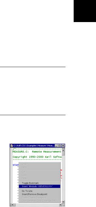
When you are creating projects with µVision2 you can insert the special function register definition of the device via the local menu in an editor window.
Use the local editor menu to insert correct register header files.

184 Chapter 9. Using On-chip Peripherals
|
|
Many of the example programs presented in this chapter begin with a line of |
|||
|
|
code that is similar to the following: |
|||
9 |
|||||
|
|
|
|||
|
#include <reg51.h> |
|
|||
|
The register definition files are located in the folder C:\KEIL\C51\INC or in sub- |
||||
|
|
||||
|
|||||
|
|
folders. The following excerpt from such a register definition file shows the |
|||
|
|
definitions for the parallel I/O ports. |
|||
|
|
|
|
|
|
|
|
sfr P0 |
= 0x80; |
// 8-bit I/O Port P0 |
|
|
|
sfr P1 |
= 0x90; |
// 8-bit I/O Port P1 |
|
|
|
sfr P2 |
= 0xA0; |
// 8-bit I/O Port P2 |
|
|
|
sfr P3 |
= 0xB0; |
// 8-bit I/O Port P3 |
|
You may define own SFR symbols directly in your C source or header files. The C51 compiler supports both: byte SFR and bit SFR symbols as shown in the following example:
sfr IE |
= |
0xA8; |
// |
Interrupt Enable |
register at |
SFR address 0xA8 |
sbit EA |
= |
IE^7; |
// |
global Interrupt |
Enable Flag |
(bit 7 of SFR IE) |
NOTES
Before you can read from or write to a Special Function Register, you must declare the SFR symbol in your source file.
Bit SFR symbols can be defined only for bit-addressable SFR registers that are located on sfr address 0x80, 0x88, 0x90, .. 0xF8.
Register Banks
The 8051 is an accumulator-based microcontroller with eight general-purpose registers (R0-R7). Each register is a single byte register. All eight general-purpose registers may be considered a bank of registers or a register bank.
The 8051 provides four register banks you can use. The primary reason for multiple register banks becomes apparent when you use interrupts.
For typical 8051 C programs there is no need to select or switch register banks. Register bank 0 is used by default.
Register bank 1, 2, or 3 are best used in interrupt service routines to avoid saving and restoring registers on the stack.

Getting Started and Creating Applications |
185 |
|
|
Interrupt Service Routines
The C51 compiler lets you write interrupt service routines in C. The compiler |
9 |
generates very efficient entry and exit code and accommodates register bank |
switching. Interrupt routines are declared as follows:
void function_name (void) interrupt interrupt_number using register_bank
The interrupt_number determines the interrupt vector address of the interrupt function. Use the following table to determine the interrupt number.
|
Interrupt Number |
Address |
0 |
(EXTERNAL INT 0) |
0003h |
1 |
(TIMER/COUNTER 0) |
000Bh |
2 |
(EXTERNAL INT 1) |
0013h |
3 |
(TIMER/COUNTER 1) |
001Bh |
4 |
(SERIAL PORT) |
0023h |
5 |
(TIMER/COUNTER 2) |
002Bh |
6 |
(PCA) |
0033h |
|
7 |
003Bh |
|
8 |
0043h |
|
9 |
004Bh |
|
10 |
0053h |
|
11 |
005Bh |
|
12 |
0063h |
|
13 |
006Bh |
|
14 |
0073h |
|
15 |
007Bh |
Interrupt Number |
Address |
16 |
0083h |
17 |
008Bh |
18 |
0093h |
19 |
009Bh |
20 |
00A3h |
21 |
00ABh |
22 |
00B3h |
23 |
00BBh |
24 |
00C3h |
25 |
00CBh |
26 |
00D3h |
27 |
00DBh |
28 |
00E3h |
29 |
00EBh |
30 |
00F3h |
31 |
00FBh |
The using attribute lets you specify a register_bank that is selected during the execution of the interrupt function. Small interrupt routines might be more efficient without the using attribute, since they use the default register bank 0. You should compare the assembly code generated both with and without the using directive to see which is more efficient in your application.
NOTE
Functions that are invoked from an interrupt procedure should be compiled with the NOAREGS directive. This ensures that the compiler does not generate absolute register accesses

|
186 |
Chapter 9. Using On-chip Peripherals |
|
|
|
|
The following example program shows a typical interrupt function: |
|
9 |
#include <reg51.h> |
// Special Function Registers of 80C51 CPU |
#pragma NOAREGS |
// do not use absolute register symbols (ARx) |
|
|
// for functions called from interrupt routines. |
|
|
|
|
static void HandleTransmitInterrupt (void) {
:
:
}
static void HandleReceiveInterrupt (void) {
:
:
}
#pragma AREGS |
// for other code it is save to use ARx symbols |
static void com_isr (void) interrupt 4 using 1 { if (TI) HandleTransmitInterrupt ();
if (RI) HandleReceiveInterrupt ();
}
In the example above an interrupt service routine for interrupt number 4 is defined. The name of the interrupt function is com_isr. Once the interrupt is invoked, the entry code saves CPU registers and selects register bank 1. When the interrupt service routine exits, the CPU registers are restored.
The following listing shows the code generated by the C51 compiler for the above interrupt routine. Note that the register bank context is swapped on entry to the interrupt routine and is restored on exit.
|
|
; FUNCTION com_isr (BEGIN) |
||
0000 |
C0E0 |
PUSH |
ACC |
; Save the Accumulator and Data |
Pointer |
|
|
|
|
0002 |
C083 |
PUSH |
DPH |
|
0004 |
C082 |
PUSH |
DPL |
|
0006 |
C0D0 |
PUSH |
PSW |
; Save PSW (and the current Register |
Bank) |
|
|
|
|
0008 |
75D008 |
MOV |
PSW,#08H |
; This selects Register Bank 1 |
|
|
: |
|
|
|
|
: |
|
|
0052 |
D0D0 |
POP |
PSW |
; Restore PSW (and prior reg bank) |
0054 |
D082 |
POP |
DPL |
|
0056 |
D083 |
POP |
DPH |
|
0058 |
D0E0 |
POP |
ACC |
; Restore the Accumulatorand DPTR |
005A |
32 |
RETI |
|
|
; FUNCTION com_isr (END)