

64 |
Chapter 4. Creating Applications |
|
|
Now you can modify existing source code or add new source files to the project. The Build Target toolbar button translates only modified or new source files and generates the executable file. µVision2 maintains a file dependency list and knows all include files used within a source file. Even the tool options are saved in the file dependency list, so that µVision2 rebuilds files only when needed. With the Rebuild Target command, all source files are translated, regardless of modifications.
Project Targets and File Groups
By using different Project Targets µVision2 lets you create several programs from a single project. You may need one target for testing and another target for a release version of your application. Each target allows individual tool settings within the same project file.
Files Groups let you group associated files together in a project. This is useful 4 for grouping files into functional blocks or for identifying engineers in your
software team. We have already used file groups in our example to separate the CPU related files from other source files. With these techniques it is easily possible to maintain complex projects with several 100 files in µVision2.
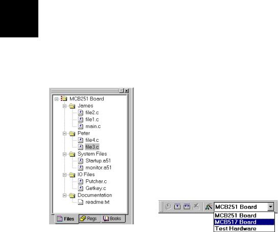
The Project – Targets, Groups, Files… dialog allows you to create project targets and file groups. We have already used this dialog to add the system configuration files. An example project structure is shown below.
The Project Windows shows all groups and the related files. Files are built and linked in the same order as shown in this window. You can move file positions with Drag & Drop. You may select a target or group name and Click to rename it. The local menu opens with a right mouse Click and allows you to:
• Set tool options |
• Add files to a group |
• Remove the item |
• Open the file. |
In the build toolbar you can quickly change the current project target to build.
Getting Started and Creating Applications |
65 |
|
|
Viewing File and Group Attributes in the
Project Window
Different icons are used in the Project Window – Files page to show the attributes of files and file groups. These icons are explained below:
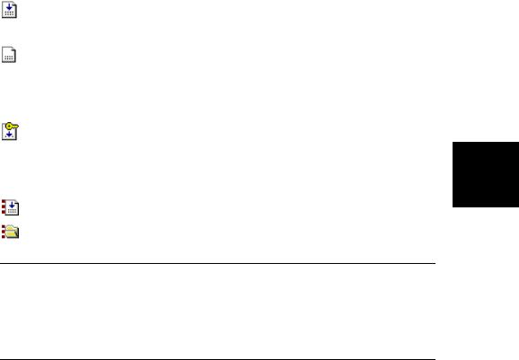
Files that are translated and linked into the project are marked with an arrow in the file icon.
Files that are excluded from the link run do not have the arrow. This is typical for document files. However you may exclude also source files when you disable Include in Target Build in the Properties dialog. See also “File and Group Specific Options – Properties Dialog” on page 87.
Read only files are marked with a key. This is typical for files that are checked into a Software Version Control System, since the SVCS makes
the local copy of such files read only. See also “Using the SVCS Menu” 4 on page 76.
Files or file groups with specific options are marked with dots. Refer to “File and Group Specific Options – Properties Dialog” on page 87 for more information.
NOTE
The different icons give you quick overview of the tool settings in the various targets of a project. The icons reflect always the attributes of the current selected target. For example, if you have set specific options on a file or file group in one target, then the dots in the icon are only shown if this target is currently selected.
66 |
Chapter 4. Creating Applications |
|
|
Overview of Configuration Dialogs
The options dialog lets you set all the tool options. Via the local menu in the Project Window – Files you may set different options for a file group or even a single file; in this case you get only the related dialog pages. With the context help button  you get help on most dialog items. The following table describes the options of the Target dialog.
|
|
Dialog Page |
Description |
|
|
|
Target |
Specify the hardware of your application. See page 62 for details. |
|
|
|
Output |
Define the output files of the tool chain and allows you to start user programs after |
|
|
|
|
the build process. See page 82 for more information. |
|
|
|
Listing |
Specify all listing files generated by the tool chain. |
|
|
|
C51 |
Set C51 Compiler specific tool options like code optimization or variable allocation. |
|
|
|
|
Refer to “Other C51 Compiler Directives” on page 80 for information. |
|
|
|
A51, AX51 |
Set assembler specific tool options like macro processing. |
|
4 |
|
|||
|
L51 Locate |
Define the location of memory classes and segments. Typical you will enable Use |
|
|
|
LX51 Locate |
Memory Layout from Target Dialog as show below to get automatic settings. |
|
|
|
|
Refer to “Locating Segments to Absolute Memory Locations” on page 86 for more |
|
|
|
|
|
information on this dialog. |
|
|
|
L51 Misc |
Other linker related settings like Warning or memory Reserve directive. |
|
|
|
|||
|
|
LX51 Misc |
|
|
|
|
Debug |
Settings for the µVision2 Debugger. Refer to page 101 for more information. |
|
|
|
Properties |
File information and special options for files and groups refer to “File and Group |
|
|
|
|
Specific Options – Properties Dialog” on page 87. |
|
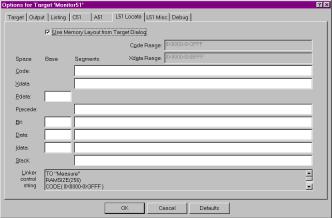
Below the L51 Locate dialog page is shown. When you enable Use Memory Layout from Target Dialog µVision2 uses the memory information from the selected Device and the Target page. You may still add additional segments to these settings.

Getting Started and Creating Applications |
67 |
|
|
Code Banking
A standard 8051 device has an address range of 64 KBytes for code space. To expand program code beyond this 64KB limit, the Keil 8051 tools support code banking. This technique lets you manage one common area and 32 banks of up to 64 Kbytes each for a total of 2 Mbytes of bank-switched memory.
For example, your hardware design |
|
|
|
|
|
|
|
|
|
|
|
|
|
|
|
may include one 32K ROM |
|
|
|
|
|
|
|
|
|
|
|
|
|
|
0xFFFF |
|
|
|
|
|
|
|
|
|
|
|
|
|
|
||
mapped from address 0000h to |
|
ROM |
|
ROM |
|
|
ROM |
|
ROM |
|
|
||||
7FFFh (known as the common area |
|
|
|
|
|
|
|
||||||||
|
Bank #0 |
|
Bank #1 |
|
|
Bank #2 |
|
Bank #3 |
|
|
|||||
or common ROM) and four 32K |
|
|
|
|
|
|
|
|
|
|
|
|
|
|
|
ROMs mapped from code address |
|
|
|
|
|
|
|
|
|
|
|
|
|
|
0x8000 |
|
|
|
|
|
|
|
|
|
|
|
|
|
|
||
|
|
|
|
|
|
|
|
|
|
|
|
|
|
||
8000h to 0FFFFh (known as the |
|
|
|
|
|
|
|
|
|
|
0x7FFF |
|
|||
|
|
|
|
|
|
|
|
|
|
|
|||||
|
|
|
|
|
|
|
|
|
|
|
|||||
code bank ROMs). The code bank |
|
|
|
|
|
|
ROM |
|
|
|
|
|
|
||
ROMs are typically selected via |
|
|
|
|
|
|
|
|
|
|
|
|
|||
|
|
|
|
|
Common |
|
|
|
|
|
4 |
||||
port bits. The figure on the right |
|
|
|
|
|
|
Area |
|
|
|
|
|
|||
|
|
|
|
|
|
|
|
|
|
|
|
|
|
||
shows this memory structure. |
|
|
|
|
|
|
|
|
|
|
0x0000 |
||||
|
|
|
|
|
|
|
|
|
|
|
|||||
Code banking is enabled and configured in the Options for Target – Target dialog. Here you enter the number of code banks supported by your hardware and the banked area. For the above memory example the entries shown on the right are required.
For the configuration of your banking hardware you need to add
the file C51\LIB\L51_BANK.A51 to
your project. Copy this file into the project folder together with the other source files of your project and add it to a file group. The
L51_BANK.A51 file must be
modified to match the your target hardware.
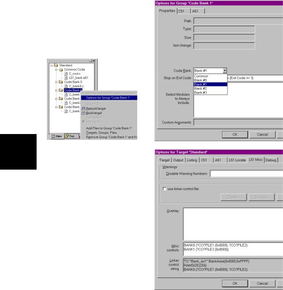
For each source file or file group of your project the code bank for the program code can be specified for in the Options – Properties dialog.
68 |
Chapter 4. Creating Applications |
|
|
The Options – Properties dialog opens with a right mouse click in the project window on the file or file group. This dialog allows you to select the code bank or the common area.
4 |
The common code area can be |
accessed in all code banks. The |
common area usually includes routines and constant data that must always be accessible, such as: interrupt routines, interrupt and reset vectors, string constants, and bank switch routines. The linker therefore locates only the program segments of a module into the bank area. However, if you can ensure that your program accesses information in constant segments only within a specific code bank, you may locate these segments into this bank using the BANKx linker directives in the dialog Options for Target – L51 Misc.
The above steps complete the configuration of a your code banking application. The µVision2 debugger fully supports code banking and allows you to test your program. If you enable “Create HEX File” in the Options for Target – Output dialog, the tools generate for each code bank a physical 64KB image that starts at address 0. You need to program these HEX files using your PROM programmer into the correct memory location of your EPROM.