

Getting Started and Creating Applications |
107 |
|
|
Debug Commands
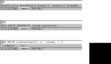
You may interact with the µVision2 debugger by entering commands in the Output Window – Command page. In the following tables all available µVision2 debug commands are listed in categories. Use the underlined characters in the command names to enter commands. For example, the WATCHSET command must be entered as WS.
During command entry, the syntax generator displays possible commands, options and parameters. As you enter commands µVision2 reduces the list of likely commands to coincide with the characters you type.
If you type B, the syntax generator reduces the commands listed.
Available command options are listed if the command is clear.
The syntax generator leads you through the command
entry and helps you to avoid 5 errors.
108 |
Chapter 5. Testing Programs |
|
|
Memory Commands
The following memory commands let you display and alter memory contents.
Command |
Description |
ASM |
Assembles in-line code. |
DEFINE |
Defines typed symbols that you may use with µVision2 debug functions. |
DISPLAY |
Display the contents of memory. |
ENTER |
Enters values into a specified memory area. |
EVALUATE |
Evaluates an expression and outputs the results. |
MAP |
Specifies access parameters for memory areas. |
UNASSEMBLE |
Disassembles program memory. |
WATCHSET |
Adds a watch variable to the Watch window. |
Program Execution Commands
Program commands let you run code and step through your program one instruction at a time.
5 |
|
|
|
|
|
Command |
Description |
|
|
|
Esc |
Stops program execution. |
|
|
|
GO |
Starts program execution. |
|
|
|
|
PSTEP |
Steps over instructions but does not step into procedures or functions. |
|
|
|
|||
|
|
OSTEP |
Steps out of the current function. |
|
|
|
TSTEP |
Steps over instructions and into functions. |
|
Breakpoint Commands
µVision2 provides breakpoints you may use to conditionally halt the execution of your target program. Breakpoints can be set on read operations, write operations and execution operations.
Command |
Description |
BREAKDISABLE |
Disables one or more breakpoints. |
BREAKENABLE |
Enables one or more breakpoints. |
BREAKKILL |
Removes one or more breakpoints from the breakpoint list. |
BREAKLIST |
Lists the current breakpoints. |
BREAKSET |
Adds a breakpoint expression to the list of breakpoints. |
Getting Started and Creating Applications |
109 |
|
|
General Commands
The following general commands do not belong in any other particular command group. They are included to make debugging easier and more convenient.
Command |
Description |
|
|
ASSIGN |
Assigns input and output sources for the Serial window. |
|
|
COVERAGE |
List code coverage statistics. |
|
|
DEFINE BUTTON |
Creates a Toolbox button. |
|
|
DIR |
Generates a directory of symbol names. |
|
|
EXIT |
Exits the µVision2 debug mode. |
|
|
INCLUDE |
Reads and executes the commands in a command file. |
|
|
KILL |
Deletes µVision2 debug functions and Toolbox buttons. |
|
|
LOAD |
Loads CPU drivers, object modules, and HEX files. |
|
|
LOG |
Creates log files, queries log status, and closes log files for the Debug |
|
|
|
window. |
|
|
MODE |
Sets the baud rate, parity, and number of stop bits for PC COM ports. |
|
|
PerformanceAnalyze |
Setup the performance analyzer or list PA information. |
|
|
RESET |
Resets CPU, memory map assignments, Performance Analyzer or |
|
|
|
predefined variables. |
|
|
SAVE |
Saves a memory range in an Intel HEX386 file. |
|
5 |
SCOPE |
Displays address assignments of modules and functions of a target |
|
|
|
program. |
|
|
SET |
Sets the string value for predefined variable. |
|
|
SETMODULE |
Assigns a source file to a module. |
|
|
|
|||
SIGNAL |
Displays signal function status and removes active signal functions. |
|
|
SLOG |
Creates log files, queries log status, and closes log files for the Serial |
|
|
|
window. |
|
|
You can interactively display and change variables, registers, and memory locations from the command window. For example, you can type the following text commands at the command prompt:
Text |
Effect |
MDH |
Display the MDH register. |
R7 = 12 |
Assign the value 12 to register R7. |
time.hour |
Displays the member hour of the time structure. |
time.hour++ |
Increments the member hour of the time structure. |
index = 0 |
Assigns the value 0 to index. |

110 |
Chapter 5. Testing Programs |
|
|
Expressions
Many debug commands accept numeric expressions as parameters. A numeric expression is a number or a complex expressions that contains numbers, debug objects, or operands. An expression may consist of any of the following components.
Component |
Description |
Bit Addresses |
Bit addresses reference bit-addressable data memory. |
Constants |
Constants are fixed numeric values or character strings. |
Line Numbers |
Line numbers reference code addresses of executable programs. When |
|
you compile or assemble a program, the compiler and assembler |
|
include line number information in the generated object module. |
Operators |
Operators include +, -, *, and /. Operators may be used to combine |
|
subexpressions into a single expression. You may use all operators that |
|
are available in the C programming language. |
Program Variables |
Program variables are those variables in your target program. They are |
(Symbols) |
often called symbols or symbolic names. |
System Variables |
System variables alter or affect the way µVision2 operates. |
Type Specifications |
Type specifications let you specify the data type of an expression or |
|
subexpression. |
5
Getting Started and Creating Applications |
111 |
|
|
Constants
The µVision2 accepts decimal constants, HEX constants, octal constants, binary constants, floating-point constants, character constants, and string constants.
Binary, Decimal, HEX, and Octal Constants
By default, numeric constants are decimal or base ten numbers. When you enter 10, this is the number ten and not the HEX value 10h. The following table shows the prefixes and suffixes that are required to enter constants in base 2 (binary), base 8 (octal), base 10 (decimal), and base 16 (HEX).
Base |
Prefix |
Suffix |
Example |
Binary: |
None |
Y or y |
11111111Y |
Decimal: |
None |
T or none |
1234T or 1234 |
Hexadecimal: |
0x or 0X |
H or h |
1234H or 0x1234 |
Octal: |
None |
Q, q, O, or o |
777q or 777Q or 777o |
Following are a few points to note about numeric constants.
|
Numbers may be grouped with the dollar sign character (“$”) to make them |
5 |
|
easier to read. For example, 1111$1111y is the same as 11111111y. |
|
|
HEX constants must begin prefixed with a leading zero when the first digit in |
|
|
the constant is A-F. |
|
|
|
|
|
By default, numeric constants are 16-bit values. They may be followed with |
|
|
an L to make them long, 32-bit values. For example: 0x1234L, 1234L, 1255HL. |
|
|
When a number is entered that is larger than the range of a 16-bit integer , the |
|
|
number is promoted automatically to a 32-bit integer. |
|

112 |
Chapter 5. Testing Programs |
|
|
Floating-Point Constants
Floating-point constants are entered in one of the following formats.
number . number number e +|- number
number . number e +|- number
For example, 4.12, 0.1e3, and 12.12e–5. In contrast with the C programming language, floating-point numbers must have a digit before the decimal point. For example, .12 is not allowed. It must be entered as 0.12.
Character Constants
The rules of the C programming language for character constants apply to the µVision2 debugger. For example, the following are all valid character constants.
'a', '1', '\n', '\v', '\x0FE', '\015'
Also escape sequences are supported as listed in the following table:
5 |
|
|
|
|
|
|
|
|
|
Sequence |
|
Description |
|
|
Sequence |
Description |
|
|
\\ |
|
Backslash character (“\”). |
|
|
\n |
Newline. |
|
|
|
\" |
|
Double quote. |
|
|
\r |
Carriage return. |
|
|
\' |
|
Single quote. |
|
|
\t |
Tab. |
|
|
\a |
|
Alert, bell. |
|
|
\0nn |
Octal constant. |
|
|
\b |
|
Backspace. |
|
|
\Xnnn |
HEX constant. |
|
|
\f |
|
Form feed. |
|
|
|
|

Getting Started and Creating Applications |
113 |
|
|
String Constants
The rules of the C programming language for string constants also apply to µVision2. For example:
"string\x007\n" |
"value of %s = %04XH\n" |
Nested strings may be required in some cases. For example, double quotes for a nested string must be escaped. For example:
"printf (\"hello world!\n\")"
In contrast with the C programming language, successive strings are not concatenated into a single string. For example, is not combined into a single string.
System Variables |
|
|||
System variables allow access to specific functions and may be used anywhere a |
|
|||
program variable or other expression is used. The following table lists the |
|
|||
available system variables, the data types, and their uses. |
5 |
|||
|
|
|
|
|
Variable |
Type |
Description |
|
|
$ |
unsigned long |
Represents the program counter. You may use $ to display and |
|
|
|
||||
|
|
change the program counter. For example, |
|
|
|
|
$ = C:0x4000 |
|
|
|
|
sets the program counter to address C:0x4000. |
|
|
_break_ |
unsigned int |
Allows you to stop executing the target program. When you set |
|
|
|
|
_break_ to a non-zero value, µVision2 halts target program |
|
|
|
|
execution. You may use this variable in user and signal functions to |
|
|
|
|
halt program execution. Refer to “Chapter 6. µVision2 Debug |
|
|
|
|
Functions” on page 131 for more information. |
|
|
_iip_ |
unsigned char |
Indicates the number of interrupts that are currently nested. Debug |
|
|
|
|
functions may use this system variable to determine in an interrupt is |
|
|
|
|
currently in process. |
|
|
states |
unsigned long |
Current value of the CPU instruction state counter; starts counting |
|
|
|
|
from 0 when your target program begins execution and increases for |
|
|
|
|
each instruction that is executed. |
|
|
|
|
NOTE: states is a read-only variable. |
|
|
itrace |
unsigned int |
Indicates whether or not trace recording is performed during target |
|
|
|
|
program execution. When itrace is 0, no trace recording is |
|
|
|
|
performed. When itrace has a non-zero value, trace information is |
|
|
|
|
recorded. Refer to page 95 for more information. |
|
|
radix |
unsigned int |
Determines the base used for numeric values displayed. radix may |
|
|
|
|
be 10 or 16. The default setting is 16 for HEX output. |
|
|
|
|
|
|
|

114 Chapter 5. Testing Programs
On-chip Peripheral Symbols
µVision2 automatically defines a number of symbols depending on the CPU you have selected for your project. There are two types of symbols that are defined: special function registers (SFRs) and CPU pin registers (VTREGs).
Special Function Registers (SFRs)
µVision2 supports all special function registers of the microcontroller you have selected. Special function registers have an associated address and may be used in expressions.
CPU Pin Registers (VTREGs)
CPU pin registers, or VTREGs, let you use the CPU’s simulated pins for input and output. VTREGs are not public symbols nor do they reside in a memory space of the CPU. They may be used in expressions, but their values and utilization are CPU dependent. VTREGs provide a way to specify signals coming into the CPU from a simulated piece of hardware. You can list these symbols with the DIR VTREG command.
5 |
|
The following table describes the VTREG symbols. The VTREG symbols that |
|
|
|
are actually available depend on the selected CPU. |
|
||
|
|
VTREG |
Description |
|
|
|
|||
|
|
AINx |
An analog input pin on the chip. Your target program may read values you write to |
|
|
|
|
AINx VTREGs. |
|
|
|
CLOCK |
The internal CPU clock frequency; specifies the number of instruction states executed |
|
|
|
|
within one second in the target CPU. The system variable states and the VTREG |
|
|
|
|
CLOCK are used to calculate the CPU execution time in seconds. CLOCK is read- |
|
|
|
|
only and derived from the XTAL frequency entry in the Options – Target dialog. |
|
|
|
PORTx |
A group of I/O pins for a port on the chip. For example, PORT2 refers to all 8 or 16 |
|
|
|
|
pins of P2. These registers allow you to simulate port I/O. |
|
|
|
SxIN |
The input buffer of serial interface x. You may write 8-bit or 9-bit values to SxIN. |
|
|
|
|
These are read by your target program. You may read SxIN to determine when the |
|
|
|
|
input buffer is ready for another character. The value 0xFFFF signals that the previous |
|
|
|
|
value is completely processed and a new value may be written. |
|
|
|
SxOUT |
The output buffer of serial interface x. µVision2 copies 8-bit or 9-bit values (as |
|
|
|
|
programmed) to the SxOUT VTREG. |
|
|
|
SxTIME |
Defines the baudrate timing of the serial interface x. When SxTIME is 1, µVision2 |
|
|
|
|
simulates the timing of the serial interface using the programmed baudrate. When |
|
|
|
|
SxTIME is 0 (the default value), the programmed baudrate timing is ignored and serial |
|
|
|
|
transmission time is instantaneous. |
|
|
|
XTAL |
The XTAL frequency of the simulated CPU as defined in the Options – Target dialog. |
|

Getting Started and Creating Applications |
115 |
|
|
NOTE
You may use the VTREGs to simulate external input and output including interfacing to internal peripherals like interrupts and timers. For example, if you toggle bit 2 of PORT3 (on the 8051 drivers), the CPU driver simulates external interrupt 0.
For the C517 CPU the following VTREG symbols for the on-chip peripheral registers are available:
CPU-pin Symbol |
Description |
|
|
AIN0 |
Analog input line AIN0 (floating-point value) |
|
|
AIN1 |
Analog input line AIN1 (floating-point value) |
|
|
AIN2 |
Analog input line AIN2 (floating-point value) |
|
|
AIN3 |
Analog input line AIN3 (floating-point value) |
|
|
AIN4 |
Analog input line AIN4 (floating-point value) |
|
|
AIN5 |
Analog input line AIN5 (floating-point value) |
|
|
AIN6 |
Analog input line AIN6 (floating-point value) |
|
|
AIN7 |
Analog input line AIN7 (floating-point value) |
|
|
AIN8 |
Analog input line AIN8 (floating-point value) |
|
|
AIN9 |
Analog input line AIN9 (floating-point value) |
|
5 |
AIN10 |
Analog input line AIN10 (floating-point value) |
|
|
AIN11 |
Analog input line AIN11 (floating-point value) |
|
|
CLOCK |
Internal CPU clock frequency for instruction execution |
|
|
PORT0 |
Digital I/O lines of PORT 0 (8-bit) |
|
|
PORT1 |
Digital I/O lines of PORT 1 (8-bit) |
|
|
PORT2 |
Digital I/O lines of PORT 2 (8-bit) |
|
|
PORT3 |
Digital I/O lines of PORT 3 (8-bit) |
|
|
PORT4 |
Digital I/O lines of PORT 4 (8-bit) |
|
|
PORT5 |
Digital I/O lines of PORT 5 (8-bit) |
|
|
PORT6 |
Digital I/O lines of PORT 6 (8-bit) |
|
|
PORT7 |
Digital I/O lines of PORT 7 (8-bit) |
|
|
PORT8 |
Digital I/O lines of PORT 8 (8-bit) |
|
|
S0IN |
Serial input for SERIAL CHANNEL 0 (9-bit) |
|
|
S0OUT |
Serial output for SERIAL CHANNEL 0 (9-bit) |
|
|
S1IN |
Serial input for SERIAL CHANNEL 1 (9-bit) |
|
|
S1OUT |
Serial output for SERIAL CHANNEL 1 (9-bit) |
|
|
STIME |
Serial timing enable |
|
|
VAGND |
Analog reference voltage VAGND (floating-point value) |
|
|
VAREF |
Analog reference voltage VAREF (floating-point value) |
|
|
XTAL |
Oscillator frequency |
|
|

116 |
Chapter 5. Testing Programs |
|
|
The following examples show how VTREGs may be used to aid in simulating your target program. In most cases, you use VTREGs in signal functions to simulate some part of your target hardware.
I/O Ports
µVision2 defines a VTREG for each I/O port: i.e. PORT2. Do not confuse these VTREGs with the SFRs for each port (i.e. P2). The SFRs can be accessed inside the CPU memory space. The VTREGs are the signals present on the pins.
With µVision2, it is easy to simulate input from external hardware. If you have a pulse train coming into a port pin, you can use a signal function to simulate the signal. For example, the following signal function inputs a square wave on P2.1 with a frequency of 1000Hz.
signal void one_thou_hz (void) { |
|
while (1) { |
/* repeat forever */ |
PORT2 |= 1; |
/* set P1.2 */ |
twatch ((CLOCK / 2) / 2000); |
/* delay for .0005 secs */ |
PORT2 &= ~1; |
/* clear P1.2 */ |
twatch ((CLOCK / 2) / 2000); |
/* delay for .0005 secs */ |
} |
/* repeat */ |
} |
|
The following command starts this signal function:
5 one_thou_hz ()
Refer to “Chapter 6. µVision2 Debug Functions” on page 131 for more information about user and signal functions.
Simulating external hardware that responds to output from a port pin is only slightly more difficult. Two steps are required. First, write a µVision2 user or signal function to perform the desired operations. Second, create a breakpoint that invokes the user function.
Suppose you use an output pin (P2.0) to enable or disable an LED. The following signal function uses the PORT2 VTREG to check the output from the CPU and display a message in the Command window.
signal void check_p20 (void) { |
|
if (PORT2 & 1)) { |
/* Test P2.0 */ |
printf ("LED is ON\n"); } |
/* 1? LED is ON */ |
else { |
/* 0? LED is OFF */ |
printf ("LED is OFF\n"): } |
|
} |
|
Now, you must add a breakpoint for writes to port 1. The following command line adds a breakpoint for all writes to PORT2.

Getting Started and Creating Applications |
117 |
|
|
BS WRITE PORT2, 1, "check_p20 ()"
Now, whenever your target program writes to PORT2, the check_P20 function prints the current status of the LED. Refer to page 96 for more information about setting breakpoints.
Serial Ports
The on-chip serial port is controlled with: S0TIME, S0IN, and S0OUT. S0IN and S0OUT represent the serial input and output streams on the CPU. S0TIME lets you specify whether the serial port timing instantaneous (STIME = 0) or the serial port timing is relative to the specified baudrate (SxTIME = 1). When S0TIME is 1, serial data displayed in the Serial window is output at the specified baudrate. When S0TIME is 0, serial data is displayed in the Serial window much more quickly.
Simulating serial input is just as easy as simulating digital input. Suppose you have an external serial device that inputs specific data periodically (every second). You can create a signal function that feeds the data into the CPU’s serial port.
signal void serial_input (void) { |
|
|
|
|
while (1) { |
/* repeat forever */ |
|
|
|
5 |
||||
twatch (CLOCK); |
/* Delay for 1 second */ |
|
||
S0IN = 'A'; |
/* Send first character */ |
|
||
twatch (CLOCK / 900); |
/* Delay for 1 character time */ |
|
||
|
/* 900 is good for 9600 baud */ |
|
|
|
S0IN = 'B'; |
/* Send next character */ |
|
|
|
twatch (CLOCK / 900); |
|
|
|
|
S0IN = 'C'; |
/* Send final character */ |
|
|
|
} |
/* repeat */ |
|
|
|
} |
|
|
|
When this signal function runs, it delays for 1 second, inputs ‘A’, ‘B’, and ‘C’ into the serial input line and repeats.
Serial output is simulated in a similar fashion using a user or signal function and a write access breakpoint as described above.

118 |
Chapter 5. Testing Programs |
|
|
Program Variables (Symbols)
µVision2 lets you access variables, or symbols, in your target program by simply typing their name. Variable names, or symbol names, represent numeric values and addresses. Symbols make the debugging process easier by allowing you to use the same names in the debugger as you use in your program.
When you load a target program module and the symbol information is loaded into the debugger. The symbols include local variables (declared within functions), the function names, and the line number information. You must enable Options for Target – Output – Debug Information. Without debug information, µVision2 cannot perform source-level and symbolic debugging.
Module Names
A module name is the name of an object module that makes up all or part of a target program. Source-level debugging information as well as symbolic information is stored in each module.
The module name is derived from the name of the source file. If the target program consists of a source file named MCOMMAND.C and the C compiler generates an object file called MCOMMAND.OBJ, the module name is
5 MCOMMAND.
Symbol Naming Conventions
The following conventions apply to symbols.
The case of symbols is ignored: SYMBOL is equivalent to Symbol.
The first character of a symbol name must be: ‘A’-’Z’, ‘a’-’z’, ‘_’, or ‘?’.
Subsequent characters may be: ‘A’-’Z’, ‘a’-’z’, ‘0’-’9’, ‘_’, or ‘?’.
NOTE
When using the ternary operator (“?:”) in µVision2 with a symbol that begins with a question mark (“?”), you must insert a space between the ternary operator and the symbol name. For example, R5 = R6 ? ?symbol : R7.
Getting Started and Creating Applications |
119 |
|
|
Fully Qualified Symbols
Symbols may be entered using a fully qualified name that includes the name of the module and name of the function in which the symbol is defined. A fully qualified symbol name is composed of the following components:
Module Name identifies the module where a symbol is defined.
Line Number identifies the address of the code generated for a particular line in the module.
Function Name identifies the function in a module where a local symbol is defined.
Symbol Name identifies the name of the symbol.
This components may combined as shown in the following table:
Symbol Components |
|
Full Qualified Symbol Name addresses … |
|
|
|
\ModuleName\LineNumber |
|
… line number LineNumber in ModuleName. |
|
|
|
\ModuleName\FunctionName |
|
… FunctionName function in ModuleName. |
|
|
|
\ModuleName\SymbolName |
|
… global symbol SymbolName in ModuleName. |
|
|
|
5 |
|||||
\ModuleName\FunctionName\SymbolName |
… local symbol SymbolName in the |
|
|||
|
|
FunctionName function in ModuleName. |
|
|
|
Examples of fully qualified symbol names: |
|
||||
|
|||||
|
|
|
|
||
Full Qualified Symbol Name |
Identifies … |
|
|
||
\MEASURE\clear_records\idx |
… local symbol idx in the clear_records function in the |
|
|
||
|
MEASURE module. |
|
|
||
\MEASURE\MAIN\cmdbuf |
… cmdbuf local symbol in the MAIN function in the |
|
|
||
|
MEASURE module. |
|
|
||
\MEASURE\sindx |
… sindex symbol in the MEASURE module. |
|
|
||
\MEASURE\225 |
… line number 225 in the MEASURE module. |
|
|
||
\MCOMMAND\82 |
… line number 82 in the MCOMMAND module. |
|
|
||
\MEASURE\TIMER0 |
… the TIMER0 symbol in the MEASURE module. This |
|
|
||
|
symbol may be a function or a global variable. |
|
|
||

120 Chapter 5. Testing Programs
Non-Qualified Symbols
Symbols may be entered using the only name of the variable or function they reference. These symbols are not fully qualified and searched in a number of tables until a matching symbol name is found. This search works as follows:
|
1. |
Register Symbols of the CPU: R0 – R15, RL0 – RH7, DPP0 – DPP3. |
|
2. |
Local Variables in the Current Function in the target program. The |
|
|
current function is determined by the value of the program counter. |
|
3. |
Static Variables in the Current Module. As with the current function, the |
|
|
current module is determined by the value of the program counter. Symbols |
|
|
in the current module represent variables that were declared in the module but |
|
|
outside a function. |
|
4. |
Global or Public Symbols of your target program. SFR symbols defined by |
|
|
µVision2 are considered to be public symbols and are also searched. |
|
5. |
Symbols Created with the µVision2 DEFINE Command. These symbols |
|
|
are used for debugging and are not a part of the target program. |
5 |
6. |
System Variables that monitor and change debugger characteristics. They |
|
||
|
|
are not a part of the target program. Refer to “System Variables” on page 113 |
|
|
for more information. |
|
7. |
CPU Driver Symbole (VTREGs) defined by the CPU driver. Refer to |
|
|
“CPU Pin Registers (VTREGs)” on page 114 for a description of VTREG |
|
|
symbols. |
NOTES
The search order for symbols changes when creating user or signal functions. µVision2 first searches the table of symbols defined in the user or signal function. Then, the above list is searched. Refer to “Chapter 6. µVision2 Debug Functions” on page 131 for more information about user and signal functions.
A literal symbol that is preceded with a back quote character (`) modifies the search order: CPU driver symbols (VTREGs) are searched instead of CPU register symbols.
Getting Started and Creating Applications |
121 |
|
|
Literal Symbols
With the back quote character (`) you get a literal symbol name. Literal symbols must be used to access:
A program variable or symbol which is identical with a predefined Reserved Word. Reserved Words are µVision2 debug commands & options, data type names, CPU register names and assembler mnemonics.
A CPU driver symbol (VTREG) that is identical to program variable name.
If a literal symbol name is given, µVision2 changes the search order for nonqualified symbols that is described above. For a literal symbol CPU Driver Symbols (VTREGs) are searched instead of CPU Register Symbols.
Examples for using Literal Symbols
If you define a variable named R5 in your program and you attempt to access it, you will actually access the R5 CPU register. To access the R5 variable, you must prefix the variable name with the back quote character.
Accessing the R5 Register |
Accessing the R5 Variable |
|
|
|
|
|
|
>R5 = 121 |
>`R5 = 212 |
|
|
|
|
|
|
If your program contains a function named clock and you attempt to clock |
5 |
||
VTREG, you will get the address of the clock function. To access the clock |
|||
VTREG, you must prefix the variable name with the back quote character. |
|||
Accessing the clock function |
Accessing the clock VTREG |
|
|
|
|||
|
|
|
|
>clock |
>`clock |
|
|
0x00000DB2 |
20000000 |
|
|

122 Chapter 5. Testing Programs
Line Numbers
Line numbers enable source-level debugging and are produced by the compiler or assembler. The line number specifies the physical address in the source module of the associated program code. Since a line number represents a code address, µVision2 lets you use in an expression. The syntax for a line number is shown in the following table.
Line Number Symbol |
Code Address … |
\LineNumber |
… for line number LineNumber in the current module. |
\ModuleName\LineNumber |
… for line number LineNumber in ModuleName. |
Example
\measure\108 |
/* |
Line |
108 |
in |
module "MEASURE" */ |
\143 |
/* |
Line |
143 |
in |
the current module */ |
Bit Addresses
|
|
Bit addresses represent bits in the memory. This includes bits in special function |
|||
5 |
|||||
|
registers. The syntax for a bit address is expression . bit_position |
||||
|
Examples |
|
|
||
|
|
|
|
|
|
|
|
ACC.2 |
/* Bit 2 |
of register A */ |
|
|
|
0x20.5 |
/* Value |
of the 8051 bit space */ |
|

Getting Started and Creating Applications |
123 |
|
|
Memory Spaces
The 8051 microcontrollers provide different memory areas for variables and program code. These memory areas are reflected in the prefixes that might be used with expressions. The prefixes available are listed in the following table.
Prefix |
Memory Space |
Description |
B: |
BIT |
Bit-addressable RAM. |
C: |
CODE |
Code Memory. |
Bx: |
CODE BANK |
Code Memory Bank; x specifies a bank number, example B1: |
D: |
DATA |
Internal, directly-addressable RAM. |
I: |
IDATA |
Internal, indirectly-addressable RAM. |
X: |
XDATA |
Xdata RAM. |
NOTE
Prefixes are not necessary with symbols since symbolic names typically have an associated memory space.
Examples
|
|
|
|
|
C:0x100 |
/* Address 0x100 in code memory */ |
|
5 |
|
I:100 |
/* Address 0x64 in internal RAM of the 8051 */ |
|
||
X:0FFFFH |
/* Address 0xFFFF in the external data memory */ |
|
||
B:0x7F |
/* Bit address 127 or 2FH.7 */ |
|
|
|
B2:0x9000 |
/* Address 0x9000 in code bank |
2 */ |
|
|
|
|
|
|
|
Type Specifications
µVision2 automatically performs implicit type casting in an expression. You may explicitly cast expressions to specific data types. Type casting follows the conventions used in the C programming language. Example:
(unsigned int) 31.2 /* gives unsigned int 31 from the float value */
Operators
µVision2 supports all operators of the C programming language. The operators have the same meaning as their C equivalents.

124 |
Chapter 5. Testing Programs |
|
|
Differences Between µVision2 and C
There are a number of differences between expressions in µVision2 and expressions in the C programming language:
µVision2 does not differentiate between uppercase and lowercase characters for symbolic names and command names.
µVision2 does not support converting an expression to a typed pointer like char * or int *. Pointer types are obtained from the symbol information in the target program. They cannot be created.
Function calls entered in the µVision2 Output Window – Command page refer to debug functions. You cannot invoke functions in your target from the command line. Refer to “Chapter 6. µVision2 Debug Functions” on page 131 for more information.
µVision2 does not support structure assignments.
Expression Examples
The following expressions were entered in the Command page of the Output 5 Window. All applicable output is included with each example. The MEASURE
example program was used for all examples.
Constant
>0x1234 |
|
/* Simple constant */ |
|
0x1234 |
|
/* Output */ |
|
>EVAL |
0x1234 |
|
|
4660T |
11064Q |
1234H '...4' |
/* Output in several number bases */ |
Register
>R1 |
/* Interrogate value of register R1 */ |
0x000A |
/* Address from ACC = 0xE0, mem type = D: */ |
>R1 = --R7 |
/* Set R1 and R7 equal to value R7-1 */ |
Function Symbol
>main |
/* Get |
address of main() |
from MEASURE.C */ |
||||||||
0x00233DA |
/* Reply, |
main starts |
at |
0x233DA */ |
|||||||
>&main |
/* Same as before */ |
|
|
|
|
||||||
0x00233DA |
|
|
|
|
|
|
|
|
|
|
|
>d main |
/* Display: address = |
main */ |
|
||||||||
0x0233DA: 76 E2 00 04 76 E3 00 |
04 |
- |
66 |
E3 |
FF F7 |
E6 |
B6 |
80 |
00 |
v...v...f...... |
|
0x0233EA: E6 B7 00 00 E6 5A 40 |
00 |
- |
E6 |
D8 |
11 80 |
E6 |
2A |
3C |
F6 |
.....Z@......*< |
|
Getting Started and Creating Applications |
|
125 |
|
|||
|
|
|
|
|||
|
|
|
|
|||
|
0x0233FA: E6 28 3C F6 E6 CE 44 00 - BF 88 E6 A8 40 00 BB D8 .(<...D.....@.. |
|
|
|||
|
0x02340A: E6 F8 7A 40 CA 00 CE 39 - E6 F8 18 44 CA 00 CE 39 ..z@...9...D... |
|
|
|||
|
Address Utilization Examples |
|
|
|
||
|
|
|
|
|
||
|
>&\measure\main\cmdbuf[0] + 10 /* Address calculation */ |
|
|
|
||
|
0x23026 |
|
|
|
|
|
|
>_RBYTE (0x233DA) |
|
/* Read byte from code address 0x233DA */ |
|
|
|
|
0x76 |
|
/* Reply */ |
|
|
|
|
Symbol Output Examples |
|
|
|
||
|
|
|
|
|
||
|
>dir \measure\main |
/* Output symbols from main() in module MEASURE */ |
|
|
||
|
R14 idx . . . uint |
/* Output */ |
|
|
||
|
R13 i . . . uint |
|
|
|
|
|
|
0x0002301C |
cmdbuf . . . array[15] of char |
|
|
|
|
|
Program Counter Examples |
|
|
|
||
|
|
|
|
|
|
|
|
>$ = main |
|
/* Set program counter to main() */ |
|
|
|
|
>dir |
|
/* points to local mem sym. |
from main() */ |
|
|
|
R14 idx . . . uint |
|
/* Output */ |
|
|
|
|
R13 i . . . uint |
|
|
|
|
|
|
0x0002301C |
cmdbuf . . . array[15] of char |
|
|
|
|
|
Program Variable Examples |
|
|
|
||
|
|
|
|
|
|
|
|
>cmdbuf |
|
/* Interrogate address from cmdbuf */ |
|
5 |
|
|
0x0002301C |
|
/* Output of address due to aggregate type (Array)*/ |
|
||
|
>cmdbuf[0] |
|
/* Output contents of first array element */ |
|
||
|
0x00 |
|
|
|
|
|
|
>I |
|
/* Output contents from i */ |
|
||
|
0x00 |
|
|
|
|
|
|
>idx |
|
/* Output contents from idx */ |
|
|
|
|
0x0000 |
|
|
|
|
|
|
>idx = DPP2 |
|
/* Set contents from index equal to register DPP2 */ |
|
|
|
|
>idx |
|
/* Output contents from idx */ |
|
|
|
|
0x0008 |
|
|
|
|
|
|
Line Number Examples |
|
|
|
||
|
|
|
|
|
||
|
>\163 |
|
/* Address of the line number #104 */ |
|
|
|
|
0x000230DA |
|
|
/* Reply */ |
|
|
|
>\MCOMMAND\91 |
|
/* A line number of module "MCOMMAND" */ |
|
|
|
|
0x000231F6 |
|
|
|
|
|
|
Operator Examples |
|
|
|
|
|
|
|
|
|
|
|
|
|
>--R5 |
|
/* Auto-decrement also for CPU registers */ |
|
|
|
|
0xFE |
|
|
|
|
|
|
>mdisplay |
|
/* Output a PUBLIC bit variable */ |
|
|
|
|
0 |
|
|
|
|
|
|
>mdisplay = 1 |
|
|
/* Change */ |
|
|
|
>mdisplay |
|
/* Check result */ |
|
|
|
|
1 |
|
|
|
|
|