

- •Chapter 1 Intel® Advanced Vector Extensions
- •1.1 About This Document
- •1.2 Overview
- •1.3.2 Instruction Syntax Enhancements
- •1.3.3 VEX Prefix Instruction Encoding Support
- •1.4 Overview AVX2
- •1.5 Functional Overview
- •1.6 General Purpose Instruction Set Enhancements
- •2.1 Detection of PCLMULQDQ and AES Instructions
- •2.2 Detection of AVX and FMA Instructions
- •2.2.1 Detection of FMA
- •2.2.3 Detection of AVX2
- •2.3.1 FMA Instruction Operand Order and Arithmetic Behavior
- •2.4 Accessing YMM Registers
- •2.5 Memory alignment
- •2.7 Instruction Exception Specification
- •2.7.1 Exceptions Type 1 (Aligned memory reference)
- •2.7.2 Exceptions Type 2 (>=16 Byte Memory Reference, Unaligned)
- •2.7.3 Exceptions Type 3 (<16 Byte memory argument)
- •2.7.5 Exceptions Type 5 (<16 Byte mem arg and no FP exceptions)
- •2.7.7 Exceptions Type 7 (No FP exceptions, no memory arg)
- •2.7.8 Exceptions Type 8 (AVX and no memory argument)
- •2.8.1 Clearing Upper YMM State Between AVX and Legacy SSE Instructions
- •2.8.3 Unaligned Memory Access and Buffer Size Management
- •2.9 CPUID Instruction
- •3.1 YMM State, VEX Prefix and Supported Operating Modes
- •3.2 YMM State Management
- •3.2.1 Detection of YMM State Support
- •3.2.2 Enabling of YMM State
- •3.2.4 The Layout of XSAVE Area
- •3.2.5 XSAVE/XRSTOR Interaction with YMM State and MXCSR
- •3.2.6 Processor Extended State Save Optimization and XSAVEOPT
- •3.2.6.1 XSAVEOPT Usage Guidelines
- •3.3 Reset Behavior
- •3.4 Emulation
- •4.1 Instruction Formats
- •4.1.1 VEX and the LOCK prefix
- •4.1.2 VEX and the 66H, F2H, and F3H prefixes
- •4.1.3 VEX and the REX prefix
- •4.1.4 The VEX Prefix
- •4.1.4.1 VEX Byte 0, bits[7:0]
- •4.1.4.2 VEX Byte 1, bit [7] - ‘R’
- •4.1.5 Instruction Operand Encoding and VEX.vvvv, ModR/M
- •4.1.6 The Opcode Byte
- •4.1.7 The MODRM, SIB, and Displacement Bytes
- •4.1.8 The Third Source Operand (Immediate Byte)
- •4.1.9.1 Vector Length Transition and Programming Considerations
- •4.1.10 AVX Instruction Length
- •4.2 Vector SIB (VSIB) Memory Addressing
- •4.3 VEX Encoding Support for GPR Instructions
- •5.1 Interpreting InstructIon Reference Pages
- •5.1.1 Instruction Format
- •5.1.2 Opcode Column in the Instruction Summary Table
- •5.1.3 Instruction Column in the Instruction Summary Table
- •5.1.4 Operand Encoding column in the Instruction Summary Table
- •5.1.5 64/32 bit Mode Support column in the Instruction Summary Table
- •5.1.6 CPUID Support column in the Instruction Summary Table
- •5.2 Summary of Terms
- •5.3 Instruction SET Reference
- •MPSADBW - Multiple Sum of Absolute Differences
- •PALIGNR - Byte Align
- •PBLENDW - Blend Packed Words
- •PHADDW/PHADDD - Packed Horizontal Add
- •PHADDSW - Packed Horizontal Add with Saturation
- •PHSUBW/PHSUBD - Packed Horizontal Subtract
- •PHSUBSW - Packed Horizontal Subtract with Saturation
- •PMOVSX - Packed Move with Sign Extend
- •PMOVZX - Packed Move with Zero Extend
- •PMULDQ - Multiply Packed Doubleword Integers
- •PMULHRSW - Multiply Packed Unsigned Integers with Round and Scale
- •PMULHUW - Multiply Packed Unsigned Integers and Store High Result
- •PMULHW - Multiply Packed Integers and Store High Result
- •PMULLW/PMULLD - Multiply Packed Integers and Store Low Result
- •PMULUDQ - Multiply Packed Unsigned Doubleword Integers
- •POR - Bitwise Logical Or
- •PSADBW - Compute Sum of Absolute Differences
- •PSHUFB - Packed Shuffle Bytes
- •PSHUFD - Shuffle Packed Doublewords
- •PSHUFLW - Shuffle Packed Low Words
- •PSIGNB/PSIGNW/PSIGND - Packed SIGN
- •PSLLDQ - Byte Shift Left
- •PSLLW/PSLLD/PSLLQ - Bit Shift Left
- •PSRAW/PSRAD - Bit Shift Arithmetic Right
- •PSRLDQ - Byte Shift Right
- •PSRLW/PSRLD/PSRLQ - Shift Packed Data Right Logical
- •PSUBB/PSUBW/PSUBD/PSUBQ -Packed Integer Subtract
- •PSUBSB/PSUBSW -Subtract Packed Signed Integers with Signed Saturation
- •PSUBUSB/PSUBUSW -Subtract Packed Unsigned Integers with Unsigned Saturation
- •PXOR - Exclusive Or
- •VPBLENDD - Blend Packed Dwords
- •VPERMD - Full Doublewords Element Permutation
- •VPERMPD - Permute Double-Precision Floating-Point Elements
- •VPERMPS - Permute Single-Precision Floating-Point Elements
- •VPERMQ - Qwords Element Permutation
- •VPSLLVD/VPSLLVQ - Variable Bit Shift Left Logical
- •VPSRAVD - Variable Bit Shift Right Arithmetic
- •VPSRLVD/VPSRLVQ - Variable Bit Shift Right Logical
- •VGATHERDPD/VGATHERQPD - Gather Packed DP FP values Using Signed Dword/Qword Indices
- •VGATHERDPS/VGATHERQPS - Gather Packed SP FP values Using Signed Dword/Qword Indices
- •VPGATHERDD/VPGATHERQD - Gather Packed Dword values Using Signed Dword/Qword Indices
- •VPGATHERDQ/VPGATHERQQ - Gather Packed Qword values Using Signed Dword/Qword Indices
- •6.1 FMA InstructIon SET Reference
- •Chapter 7 Instruction Set Reference - VEX-Encoded GPR Instructions
- •7.1 Instruction Format
- •7.2 INSTRUCTION SET REFERENCE
- •BZHI - Zero High Bits Starting with Specified Bit Position
- •INVPCID - Invalidate Processor Context ID
- •Chapter 8 Post-32nm Processor Instructions
- •8.1 Overview
- •8.2 CPUID Detection of New Instructions
- •8.4 Vector Instruction Exception Specification
- •8.6 Using RDRAND Instruction and Intrinsic
- •8.7 Instruction Reference
- •A.1 AVX Instructions
- •A.2 Promoted Vector Integer Instructions in AVX2
- •B.1 Using Opcode Tables
- •B.2 Key to Abbreviations
- •B.2.1 Codes for Addressing Method
- •B.2.2 Codes for Operand Type
- •B.2.3 Register Codes
- •B.2.4 Opcode Look-up Examples for One, Two, and Three-Byte Opcodes
- •B.2.4.1 One-Byte Opcode Instructions
- •B.2.4.2 Two-Byte Opcode Instructions
- •B.2.4.3 Three-Byte Opcode Instructions
- •B.2.4.4 VEX Prefix Instructions
- •B.2.5 Superscripts Utilized in Opcode Tables
- •B.3 One, Two, and THREE-Byte Opcode Maps
- •B.4.1 Opcode Look-up Examples Using Opcode Extensions
- •B.4.2 Opcode Extension Tables
- •B.5 Escape Opcode Instructions
- •B.5.1 Opcode Look-up Examples for Escape Instruction Opcodes
- •B.5.2 Escape Opcode Instruction Tables
- •B.5.2.1 Escape Opcodes with D8 as First Byte
- •B.5.2.2 Escape Opcodes with D9 as First Byte
- •B.5.2.3 Escape Opcodes with DA as First Byte
- •B.5.2.4 Escape Opcodes with DB as First Byte
- •B.5.2.5 Escape Opcodes with DC as First Byte
- •B.5.2.6 Escape Opcodes with DD as First Byte
- •B.5.2.7 Escape Opcodes with DE as First Byte
- •B.5.2.8 Escape Opcodes with DF As First Byte

POST-32NM PROCESSOR INSTRUCTIONS
CHAPTER 8 POST-32NM PROCESSOR INSTRUCTIONS
8.1OVERVIEW
This chapter describes additional instructions targeted for Intel 64 architecture processors in process technology smaller than 32 nm. These instructions include:
•Two instructions to support 16-bit floating-point data type conversion to and from single-precision floating-point type. Conversion to packed 16-bit floating-point values from packed single-precision floating-point values also provides rounding control using an immediate byte. These float-16 instructions convert packed data types of different sizes following the same manner as the 256-bit vector SIMD extension, AVX.
•One instruction that generates random numbers of 16/32/64 bit wide random integers. The random number generator instruction operates on general-purpose registers.
•Four instructions that allow software working in 64-bit environment to read and write FS base and GS base registers in all privileged levels.
8.2CPUID DETECTION OF NEW INSTRUCTIONS
Application using float 16 instruction must follow a detection sequence similar to AVX to ensure:
•The OS has enabled YMM state management support,
•The processor support AVX as indicated by the CPUID feature flag, i.e. CPUID.01H:ECX.AVX[bit 28] = 1.
•The processor support 16-bit floating-point conversion instructions via a CPUID feature flag (CPUID.01H:ECX.F16C[bit 29] = 1).
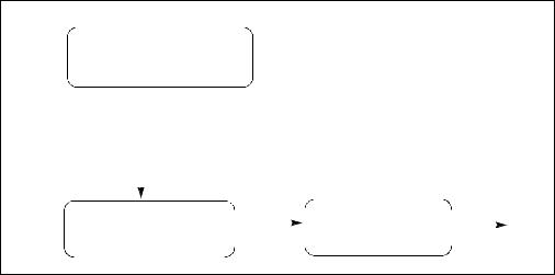
Application detection of Float-16 conversion instructions follow the general procedural flow in Figure 8-1.
Ref. # 319433-011 |
8-1 |
POST-32NM PROCESSOR INSTRUCTIONS
Check feature flag
CPUID.1H:ECX.OXSAVE = 1?
|
OS provides processor |
|
extended state management |
Yes |
Implied HW support for |
|
XSAVE, XRSTOR, XGETBV, XFEATURE_ENABLED_MASK |
|
|
Check enabled YMM state in |
|
Check feature flags |
|
|
|
|
|
||
XFEM via XGETBV |
State |
for AVX and F16C |
ok to use |
|
|
enabled |
|
Instructions |
|
Figure 8-1. General Procedural Flow of Application Detection of Float-16
----------------------------------------------------------------------------------------
INT supports_f16c() { ; result in eax mov eax, 1
cpuid
and ecx, 038000000H
cmp ecx, 038000000H; check OSXSAVE, AVX, F16C feature flags jne not_supported
; processor supports AVX,F16C instructions and XGETBV is enabled by OS mov ecx, 0; specify 0 for XFEATURE_ENABLED_MASK register
XGETBV; result in EDX:EAX and eax, 06H
cmp eax, 06H; check OS has enabled both XMM and YMM state support jne not_supported
mov eax, 1 jmp done
NOT_SUPPORTED: mov eax, 0
done:
8-2 |
Ref. # 319433-011 |
POST-32NM PROCESSOR INSTRUCTIONS
}
-------------------------------------------------------------------------------
RDRAND, RDFSBASE/RDGSBASE, WRFSBASE/WRGSBASE operates on general purpose registers only.
Before software attempts to use the RDRAND instruction, it must check that the CPUID feature flag indicating processor supports RDRAND, i.e., if CPUID.01H:ECX.RDRAND[bit 30] = 1.
CPUID.(EAX=07H, ECX=0H):EBX.FSGSBASE[bit 0] = 1 indicates availability of instructions that are primarily targeting use by system software manipulating the base of FS and GS segments. These instructions require enabling by OS (see Section 8.5). An OS may provide programming interfaces indicating its support of application use of RDFSBASE/RDGSBASE, WRFSBASE/WRGSBASE instructions.
8.316-BIT FLOATING-POINT DATA TYPE SUPPORT
Two new instructions support half-precision floating-point data type with conversion to and from single-precision floating-point data types. Table 8-1 gives the length, precision, and approximate normalized range that can be represented by half and single precision data types. Denormal values are also supported in these types.
Table 8-1. Length, Precision, and Range of Floating-Point Data Types
Data Type |
Length |
Precision |
Approximate Normalized Range |
|
|
|
(Bits) |
|
|
|
|
Binary |
Decimal |
|
|
|
|
||
|
|
|
|
|
Half Precision |
16 |
11 |
2–14 to 215 |
3.1 × 10⁻⁵ to 6.50 × 10⁴ |
Single Precision |
32 |
24 |
2–126 to 2127 |
1.18 × 10–38 to 3.40 × 1038 |
Double Precision |
64 |
53 |
2–1022 to 21023 |
2.23 × 10–308 to 1.79 × 10308 |
Table 8-2 shows the floating-point encodings for zeros, denormalized finite numbers, normalized finite numbers, infinities, and NaNs for each of the three floating-point data types.
Ref. # 319433-011 |
8-3 |
POST-32NM PROCESSOR INSTRUCTIONS
Table 8-2. Half-Precision Floating-Point Number and NaN Encodings
|
Class |
|
Sign |
Biased Exponent |
Significand |
|
|||
|
|
|
|
|
|
|
|
|
|
|
|
|
|
|
|
|
Integer1 |
Fraction |
|
Positive |
|
+∞ |
|
0 |
11..11 |
|
1 |
00..00 |
|
|
|
|
|
|
|
|
|
|
|
|
|
+Normals |
|
0 |
11..10 |
|
1 |
11..11 |
|
|
|
|
|
. |
. |
|
. |
. |
|
|
|
|
|
. |
. |
|
. |
. |
|
|
|
|
|
0 |
00..01 |
|
1 |
00..00 |
|
|
|
|
|
|
|
|
|
|
|
|
|
+Denormals |
|
0 |
00..00 |
|
0 |
11.11 |
|
|
|
|
|
. |
. |
|
. |
. |
|
|
|
|
|
. |
. |
|
. |
. |
|
|
|
|
|
0 |
00..00 |
|
0 |
00..01 |
|
|
|
|
|
|
|
|
|
|
|
|
|
+Zero |
|
0 |
00..00 |
|
0 |
00..00 |
|
|
|
|
|
|
|
|
|
|
|
Negative |
|
−Zero |
|
1 |
00..00 |
|
0 |
00..00 |
|
|
|
|
|
|
|
|
|
|
|
|
|
−Denormals |
|
1 |
00..00 |
|
0 |
00..01 |
|
|
|
|
|
. |
. |
|
. |
. |
|
|
|
|
|
. |
. |
|
. |
. |
|
|
|
|
|
1 |
00..00 |
|
0 |
11..11 |
|
|
|
|
|
|
|
|
|
|
|
|
|
−Normals |
|
1 |
00..01 |
|
1 |
00..00 |
|
|
|
|
|
. |
. |
|
. |
. |
|
|
|
|
|
. |
. |
|
. |
. |
|
|
|
|
|
1 |
11..10 |
|
1 |
11..11 |
|
|
|
|
|
|
|
|
|
|
|
|
|
-• |
|
1 |
11..11 |
|
1 |
00..00 |
|
|
|
|
|
|
|
|
|
|
|
NaNs |
|
SNaN |
|
X |
11..11 |
|
1 |
0X..XX2 |
|
|
|
QNaN |
|
X |
11..11 |
|
1 |
1X..XX |
|
|
|
|
|
|
|
|
|
|
|
|
|
QNaN |
|
1 |
11..11 |
|
1 |
10..00 |
|
|
|
Floating-Point |
|
|
|
|
|
|
|
|
|
Indefinite |
|
|
|
|
|
|
|
|
|
|
|
|
|
|
|
||
|
|
Half-Precision: |
|
← 5Bits → |
|
← 10 Bits → |
|||
|
|
Single-Precision; |
|
← 8 Bits |
→ |
|
← 23Bits |
→ |
|
|
|
Double-Precision; |
|
← 11 Bits → |
|
← 52Bits |
→ |
||
NOTES:
1.Integer bit is implied and not stored in memory format.
2.The fraction for SNaN encodings must be non-zero with the most-significant bit 0.
3.The most-significant bit of the fraction for QNaN encoding must be 1.
8-4 |
Ref. # 319433-011 |

POST-32NM PROCESSOR INSTRUCTIONS
Half-precision floating-point data type consists of a sign bit, a 5-bit exponent field, and a 11-bit significand field. The 11-bit significand consists of an implied integer bit that is not stored and a 10-bit fraction field that is stored as the 10 least-significant bits along with the sign bit (bit 15) and the exponent field (bits 14:10), see Figure 8-2.
|
|
|
|
|
|
|
|
Sign |
|
|
Half Precision |
||
|
|
|
|
|
|
|
|
|
|
|
|
|
|
|
|
|
|
|
|
|
|
|
|
|
|
|
Floating-Point |
|
|
|
|
|
|
|
15 14 |
9 |
0 |
||||
|
|
|
|
|
|
|
|
||||||
|
|
|
|
Sign |
|
|
|
|
|
|
Single Precision |
||
|
|
|
|
|
|
|
|
|
|
|
|
|
|
|
|
|
|
|
|
|
|
|
|
|
|
|
Floating-Point |
|
|
|
31 30 |
23 22 |
|
|
|
0 |
|||||
|
|
|
|
|
|
|
|||||||
Sign |
|
|
|
|
|
|
|
|
|
|
Double Precision |
||
|
|
|
|
|
|
|
|
|
|
|
|
|
|
|
|
|
|
|
|
|
|
|
|
|
|
|
|
|
|
|
|
|
|
|
|
|
|
|
|
|
Floating-Point |
63 62 |
52 51 |
|
|
|
|
|
|
|
0 |
|
|||
Figure 8-2. Floating-Point Data Types
The exponent of each floating-point data type is encoded in biased format, the bias constant is 15 for half-precision floating-point data type. When storing floating-point values in memory, half-precision values are stored in 2 consecutive bytes in memory. Table 8-3 shows how the real number 178.125 (in ordinary decimal format) is stored in IEEE Standard 754 floating-point format. The table lists a progression of real number notations that leads to the half-precision, 16-bit floating-point format.
Table 8-3. Real and Floating-Point Number Notation
Notation |
|
Value |
|
|
|
|
|
Ordinary Decimal |
178.125 |
|
|
|
|
|
|
Scientific Decimal |
1.78125E10 2 |
|
|
Scientific Binary |
1.0110010001E2111 |
|
|
Scientific Binary |
1.0110010001E210110 |
|
|
(Biased Exponent) |
|
|
|
|
|
|
|
Half-Precision Format |
Sign |
Biased Exponent |
Normalized Significand |
|
|
|
|
|
0 |
10110 |
0110010001 |
|
|
|
1. (Implied) |
|
|
|
|
Ref. # 319433-011 |
8-5 |
POST-32NM PROCESSOR INSTRUCTIONS
8.3.1Half-Precision Floating-Point Conversion
Half-precision floating-point values are not used by the processor directly for arithmetic operations. Two instructions, VCVTPH2PS, VCVTPS2PH, provide conversion between half-precision and single-precision floating-point values.
The conversion operations of VCVTPS2PH allow programmer to specify rounding control using control fields in an immediate byte. The effects of the immediate byte are listed in Table 8-4.
Rounding control can use Imm[2] to select an override RC field specified in Imm[1:0] or use MXCSR setting.
Table 8-4. Immediate Byte Encoding for 16-bit Floating-Point Conversion Instructions
Bits |
Field Name/value |
Description |
Comment |
|
|
|
|
Imm[1:0] |
RC=00B |
Round to nearest even |
If Imm[2] = 0 |
|
|
|
|
|
RC=01B |
Round down |
|
|
|
|
|
|
RC=10B |
Round up |
|
|
|
|
|
|
RC=11B |
Truncate |
|
|
|
|
|
Imm[2] |
MS1=0 |
Use imm[1:0] for round- |
Ignore MXCSR.RC |
|
|
ing |
|
|
|
|
|
|
MS1=1 |
Use MXCSR.RC for round- |
|
|
|
ing |
|
|
|
|
|
Imm[7:3] |
Ignored |
Ignored by processor |
|
|
|
|
|
VCVTPH2PS and VCVTPS2PH are subject to SIMD floating-point exceptions. Specifically, they can cause invalid operation exception (see Table 8-6), the result of which is shown in Table 8-5.
Table 8-5. Non-Numerical Behavior for VCVTPH2PS, VCVTPS2PH
Source Operands |
Masked Result |
Unmasked Result |
|
|
|
QNaN |
QNaN11 |
QNaN11 (not an exception) |
SNaN |
QNaN12 |
None |
NOTES:
1.The half precision output QNaN1 is created from the single precision input QNaN as follows: the sign bit is preserved, the 8-bit exponent FFH is replaced by the 5-bit exponent 1FH, and the 24-bit significand is truncated to an 11-bit significand by removing its 14 least significant bits.
8-6 |
Ref. # 319433-011 |
POST-32NM PROCESSOR INSTRUCTIONS
2.The half precision output QNaN1 is created from the single precision input SNaN as follows: the sign bit is preserved, the 8-bit exponent FFH is replaced by the 5-bit exponent 1FH, and the 24-bit significand is truncated to an 11-bit significand by removing its 14 least significant bits. The second most significant bit of the significand is changed from 0 to 1 to convert the signaling NaN into a quiet NaN.
Table 8-6. Invalid Operation for VCVTPH2PS, VCVTPS2PH
Instruction |
Condition |
Masked Result |
Unmasked Result |
|
|
|
|
VCVTPH2PS |
SRC = NaN |
See Table 8-5 |
#I=1 |
|
|
|
|
VCVTPS2PH |
SRC = NaN |
SeeTable 8-5 |
#I=1 |
|
|
|
|
VCVTPS2PH can cause denormal exceptions if the value of the source operand is denormal relative to the numerical range represented by the source format (see Table 8-7).
Table 8-7. Denormal Condition for VCVTPS2PH
Instruction |
Condition |
Masked Result1 |
Unmasked Result |
VCVTPH2PS |
SRC is denormal relative |
res = Result rounded to the |
Same as masked |
|
to input format1 |
destination precision and using the |
result. |
|
|
bounded exponent, but only if no |
|
|
|
unmasked post-computation |
|
|
|
exception occurs. |
|
|
|
#DE unchanged |
|
|
|
|
|
VCVTPS2PH |
SRC is denormal relative |
res = Result rounded to the |
#DE=1 |
|
to input format1 |
destination precision and using the |
|
|
|
bounded exponent, but only if no |
|
|
|
unmasked post-computation |
|
|
|
exception occurs. |
|
|
|
#DE=1 |
|
|
|
|
|
NOTES:
1. Masked and unmasked result is shown in Table 7-7.
VCVTPS2PH can cause an underflow exception if the result of the conversion is less than the underflow threshold for half-precision floating-point data type , i.e. | x | < 1.0 2−14.
Ref. # 319433-011 |
8-7 |
POST-32NM PROCESSOR INSTRUCTIONS
Table 8-8. Underflow Condition for VCVTPS2PH
Instruction |
Condition |
Masked Result1 |
Unmasked Result |
VCVTPS2PH |
Result < smallest |
Result = +0 or -0, denormal, |
#UE=1, |
|
destination precision |
normal. |
#PE = 1 if the |
|
finial normal value2 |
#UE =1. |
result is inexact. |
|
|
#PE = 1 if the result is inexact. |
|
|
|
|
|
NOTES:
1.Masked and unmasked result is shown in Table 7-7.
2.If FTZ is not set ( MXCSR.FTZ = 1 ), masked and unmasked result is shown in Table 7-8. If FTZ is set (MXCSR.FTZ = 1), inexact result = +0 or - 0, #PE and #UE are reported.
VCVTPS2PH can cause an overflow exception if the result of the conversion is greater than the maximum representable value for half-precision floating-point data type, i.e. | x | ≥ 1.0 216.
Table 8-9. Overflow Condition for VCVTPS2PH
Instruction |
Condition |
Masked Result |
Unmasked Result |
|
|
|
|
VCVTPS2PH |
Result ≥ largest |
Result = +Inf or -Inf. |
#OE=1. |
|
destination precision |
#OE=1. |
|
|
finial normal value1 |
|
|
VCVTPS2PH can cause an inexact exception if the result of the conversion is not exactly representable in the destination format.
Table 8-10. Inexact Condition for VCVTPS2PH
Instruction |
Condition |
Masked Result1 |
Unmasked Result |
VCVTPS2PH |
The result is not |
res = Result rounded to the |
Only if no underflow/overflow |
|
representable in |
destination precision and |
condition occurred, or if the |
|
the destination |
using the bounded |
corresponding exceptions are |
|
format |
exponent, but only if no |
masked: |
|
|
unmasked underflow or |
• Set #OE if masked overflow |
|
|
overflow conditions occur |
and set result as described |
|
|
(this exception can occur in |
above for masked overflow. |
|
|
|
|
|
|
the presence of a masked |
• Set #UE if masked underflow |
|
|
underflow or overflow). |
|
|
|
and set result as described |
|
|
|
#PE=1. |
above for masked underflow. |
|
|
|
If neither underflow nor |
|
|
|
overflow, result equals the result |
|
|
|
rounded to the destination |
|
|
|
precision and using the bounded |
|
|
|
exponent set #PE = 1. |
|
|
|
|
8-8 |
Ref. # 319433-011 |