

Intel® 64 and IA-32 Architectures
Software Developer’s Manual
Volume 2B:
Instruction Set Reference, N-Z
NOTE: The Intel 64 and IA-32 Architectures Software Developer's Manual consists of five volumes: Basic Architecture, Order Number 253665;
Instruction Set Reference A-M, Order Number 253666; Instruction Set Reference N-Z, Order Number 253667; System Programming Guide, Part 1, Order Number 253668; System Programming Guide, Part 2, Order Number 253669. Refer to all five volumes when evaluating your design needs.
Order Number: 253667-022US
November 2006

INFORMATION IN THIS DOCUMENT IS PROVIDED IN CONNECTION WITH INTEL PRODUCTS. NO LICENSE, EXPRESS OR IMPLIED, BY ESTOPPEL OR OTHERWISE, TO ANY INTELLECTUAL PROPERTY RIGHTS IS GRANTED BY THIS DOCUMENT. EXCEPT AS PROVIDED IN INTEL’S TERMS AND CONDITIONS OF SALE FOR SUCH PRODUCTS, INTEL ASSUMES NO LIABILITY WHATSOEVER, AND INTEL DISCLAIMS ANY EXPRESS OR IMPLIED WARRANTY, RELATING TO SALE AND/OR USE OF INTEL PRODUCTS INCLUDING LIABILITY OR WARRANTIES RELATING TO FITNESS FOR A PARTICULAR PURPOSE, MERCHANTABILITY, OR INFRINGEMENT OF ANY PATENT, COPYRIGHT OR OTHER INTELLECTUAL PROPERTY RIGHT. INTEL PRODUCTS ARE NOT INTENDED FOR USE IN MEDICAL, LIFE SAVING, OR LIFE SUSTAINING APPLICATIONS.
Intel may make changes to specifications and product descriptions at any time, without notice.
Developers must not rely on the absence or characteristics of any features or instructions marked “reserved” or “undefined.” Improper use of reserved or undefined features or instructions may cause unpredictable behavior or failure in developer's software code when running on an Intel processor. Intel reserves these features or instructions for future definition and shall have no responsibility whatsoever for conflicts or incompatibilities arising from their unauthorized use.
The Intel® 64 architecture processors may contain design defects or errors known as errata. Current characterized errata are available on request.
Hyper-Threading Technology requires a computer system with an Intel® processor supporting HyperThreading Technology and an HT Technology enabled chipset, BIOS and operating system. Performance will vary depending on the specific hardware and software you use. For more information, see http://www.intel.com/technology/hyperthread/index.htm; including details on which processors support HT Technology.
Intel® Virtualization Technology requires a computer system with an enabled Intel® processor, BIOS, virtual machine monitor (VMM) and for some uses, certain platform software enabled for it. Functionality, performance or other benefits will vary depending on hardware and software configurations. Intel® Virtualization Technology-enabled BIOS and VMM applications are currently in development.
64-bit computing on Intel architecture requires a computer system with a processor, chipset, BIOS, operating system, device drivers and applications enabled for Intel® 64 architecture. Processors will not operate (including 32-bit operation) without an Intel® 64 architecture-enabled BIOS. Performance will vary depending on your hardware and software configurations. Consult with your system vendor for more information.
Enabling Execute Disable Bit functionality requires a PC with a processor with Execute Disable Bit capability and a supporting operating system. Check with your PC manufacturer on whether your system delivers Execute Disable Bit functionality.
Intel, Pentium, Intel Xeon, Intel NetBurst, Intel Core Solo, Intel Core Duo, Intel Core 2 Duo, Intel Core 2 Extreme, Intel Pentium D, Itanium, Intel SpeedStep, MMX, and VTune are trademarks or registered trademarks of Intel Corporation or its subsidiaries in the United States and other countries.
*Other names and brands may be claimed as the property of others.
Contact your local Intel sales office or your distributor to obtain the latest specifications and before placing your product order.
Copies of documents which have an ordering number and are referenced in this document, or other Intel literature, may be obtained from:
Intel Corporation P.O. Box 5937
Denver, CO 80217-9808
or call 1-800-548-4725
or visit Intel’s website at http://www.intel.com
Copyright © 1997-2006 Intel Corporation
ii Vol. 2B

CHAPTER 4
INSTRUCTION SET REFERENCE, N-Z
4.1INSTRUCTIONS (N-Z)
Chapter 4 continues an alphabetical discussion of Intel® 64 and IA-32 instructions (N-Z). See also: Chapter 3, “Instruction Set Reference, A-M,” in the Intel® 64 and IA-32 Architectures Software Developer’s Manual, Volume 2A.
Vol. 2B 4-1

INSTRUCTION SET REFERENCE, N-Z
NEG—Two's Complement Negation
|
|
64-Bit |
Compat/ |
|
Opcode |
Instruction |
Mode |
Leg Mode |
Description |
F6 /3 |
NEG r/m8 |
Valid |
Valid |
Two's complement negate |
|
|
|
|
r/m8. |
REX + F6 /3 |
NEG r/m8* |
Valid |
N.E. |
Two's complement negate |
|
|
|
|
r/m8. |
F7 /3 |
NEG r/m16 |
Valid |
Valid |
Two's complement negate |
|
|
|
|
r/m16. |
F7 /3 |
NEG r/m32 |
Valid |
Valid |
Two's complement negate |
|
|
|
|
r/m32. |
REX.W + F7 /3 |
NEG r/m64 |
Valid |
N.E. |
Two's complement negate |
|
|
|
|
r/m64. |
NOTES:
*In 64-bit mode, r/m8 can not be encoded to access the following byte registers if a REX prefix is used: AH, BH, CH, DH.
Description
Replaces the value of operand (the destination operand) with its two's complement. (This operation is equivalent to subtracting the operand from 0.) The destination operand is located in a general-purpose register or a memory location.
This instruction can be used with a LOCK prefix to allow the instruction to be executed atomically.
In 64-bit mode, the instruction’s default operation size is 32 bits. Using a REX prefix in the form of REX.R permits access to additional registers (R8-R15). Using a REX prefix in the form of REX.W promotes operation to 64 bits. See the summary chart at the beginning of this section for encoding data and limits.
Operation
IF DEST = 0
THEN CF ← 0;
ELSE CF ← 1;
FI;
DEST ← [– (DEST)]
Flags Affected
The CF flag set to 0 if the source operand is 0; otherwise it is set to 1. The OF, SF, ZF, AF, and PF flags are set according to the result.
4-2 Vol. 2B
|
INSTRUCTION SET REFERENCE, N-Z |
Protected Mode Exceptions |
|
#GP(0) |
If the destination is located in a non-writable segment. |
|
If a memory operand effective address is outside the CS, DS, |
|
ES, FS, or GS segment limit. |
|
If the DS, ES, FS, or GS register contains a NULL segment |
|
selector. |
#SS(0) |
If a memory operand effective address is outside the SS |
|
segment limit. |
#PF(fault-code) |
If a page fault occurs. |
#AC(0) |
If alignment checking is enabled and an unaligned memory |
|
reference is made while the current privilege level is 3. |
Real-Address Mode Exceptions |
|
#GP |
If a memory operand effective address is outside the CS, DS, |
|
ES, FS, or GS segment limit. |
#SS |
If a memory operand effective address is outside the SS |
|
segment limit. |
Virtual-8086 Mode Exceptions |
|
#GP(0) |
If a memory operand effective address is outside the CS, DS, |
|
ES, FS, or GS segment limit. |
#SS(0) |
If a memory operand effective address is outside the SS |
|
segment limit. |
#PF(fault-code) |
If a page fault occurs. |
#AC(0) |
If alignment checking is enabled and an unaligned memory |
|
reference is made. |
Compatibility Mode Exceptions
Same as for protected mode exceptions.
64-Bit Mode Exceptions
#SS(0) |
If a memory address referencing the SS segment is in a non-canonical |
|
form. |
#GP(0) |
If the memory address is in a non-canonical form. |
#PF(fault-code) For a page fault. #AC(0)
INSTRUCTION SET REFERENCE, N-Z
NOP—No Operation
|
|
Instructio |
64-Bit |
Compat/ |
|
Opcode |
|
n |
Mode |
Leg Mode |
Description |
90 |
|
NOP |
Valid |
Valid |
One byte no-operation instruction. |
0F 1F |
/0 |
NOP |
Valid |
Valid |
Multi-byte no-operation instruction. |
|
|
r/m16 |
|
|
|
0F 1F |
/0 |
NOP |
Valid |
Valid |
Multi-byte no-operation instruction. |
|
|
r/m32 |
|
|
|
|
|
|
|
|
|
Description
This instruction performs no operation. It is a one-byte or multi-byte NOP that takes up space in the instruction stream but does not impact machine context, except for the EIP register.
The multi-byte form of NOP is available on processors with model encoding:
•CPUID.01H.EAX[Bytes 11:8] = 0110B or 1111B
The multi-byte NOP instruction does not alter the content of a register and will not issue a memory operation. The instruction’s operation is the same in non-64-bit modes and 64-bit mode.
Operation
The one-byte NOP instruction is an alias mnemonic for the XCHG (E)AX, (E)AX instruction.
The multi-byte NOP instruction performs no operation on supported processors and generates undefined opcode exception on processors that do not support the multibyte NOP instruction.
The memory operand form of the instruction allows software to create a byte sequence of “no operation” as one instruction. For situations where multiple-byte NOPs are needed, the recommended operations (32-bit mode and 64-bit mode) are:
Table 4-1. Recommended Multi-Byte Sequence of NOP Instruction
Length |
Assembly |
Byte Sequence |
|||
|
|
|
|
|
|
2 bytes |
66 NOP |
66 90H |
|
|
|
3 bytes |
NOP DWORD ptr [EAX] |
0F 1F |
00H |
|
|
4 bytes |
NOP DWORD ptr [EAX + 00H] |
0F 1F |
40 |
00H |
|
5 bytes |
NOP DWORD ptr [EAX + EAX*1 + 00H] |
0F 1F |
44 |
00 |
00H |
6 bytes |
66 NOP DWORD ptr [EAX + EAX*1 + 00H] |
66 0F 1F |
44 |
00 00H |
|
|
|
|
|
|
|
4-4 Vol. 2B
INSTRUCTION SET REFERENCE, N-Z
Table 4-1. Recommended Multi-Byte Sequence of NOP Instruction (Contd.)
Length |
Assembly |
Byte Sequence |
|
|
|
|
|
|
|
|
|
7 bytes |
NOP DWORD ptr [EAX + 00000000H] |
0F 1F 80 |
00 00 00 |
00H |
|
8 bytes |
NOP DWORD ptr [EAX + EAX*1 + 00000000H] |
0F 1F 84 |
00 00 00 |
00 |
00H |
9 bytes |
66 NOP DWORD ptr [EAX + EAX*1 + |
66 0F 1F |
84 00 00 |
00 |
00 |
|
00000000H] |
00H |
|
|
|
|
|
|
|
|
|
Flags Affected
None.
Exceptions (All Operating Modes)
None.
Vol. 2B 4-5
INSTRUCTION SET REFERENCE, N-Z
NOT—One's Complement Negation
|
Instructio |
64-Bit |
Compat/ |
|
Opcode |
n |
Mode |
Leg Mode |
Description |
F6 /2 |
NOT r/m8 |
Valid |
Valid |
Reverse each bit of r/m8. |
REX + F6 /2 |
NOT r/m8* |
Valid |
N.E. |
Reverse each bit of r/m8. |
F7 /2 |
NOT r/m16 |
Valid |
Valid |
Reverse each bit of r/m16. |
F7 /2 |
NOT r/m32 |
Valid |
Valid |
Reverse each bit of r/m32. |
REX.W + F7 |
NOT r/m64 |
Valid |
N.E. |
Reverse each bit of r/m64. |
/2 |
|
|
|
|
|
|
|
|
|
NOTES: |
|
|
|
|
*In 64-bit mode, r/m8 can not be encoded to access the following byte registers if a REX prefix is used: AH, BH, CH, DH.
Description
Performs a bitwise NOT operation (each 1 is set to 0, and each 0 is set to 1) on the destination operand and stores the result in the destination operand location. The destination operand can be a register or a memory location.
This instruction can be used with a LOCK prefix to allow the instruction to be executed atomically.
In 64-bit mode, the instruction’s default operation size is 32 bits. Using a REX prefix in the form of REX.R permits access to additional registers (R8-R15). Using a REX prefix in the form of REX.W promotes operation to 64 bits. See the summary chart at the beginning of this section for encoding data and limits.
Operation
DEST ← NOT DEST;
Flags Affected
None.
Protected Mode Exceptions
#GP(0) |
If the destination operand points to a non-writable segment. |
|
If a memory operand effective address is outside the CS, DS, |
|
ES, FS, or GS segment limit. |
|
If the DS, ES, FS, or GS register contains a NULL segment |
|
selector. |
#SS(0) |
If a memory operand effective address is outside the SS |
|
segment limit. |
#PF(fault-code) |
If a page fault occurs. |
4-6 Vol. 2B
|
INSTRUCTION SET REFERENCE, N-Z |
#AC(0) |
If alignment checking is enabled and an unaligned memory |
|
reference is made while the current privilege level is 3. |
Real-Address Mode Exceptions |
|
#GP |
If a memory operand effective address is outside the CS, DS, |
|
ES, FS, or GS segment limit. |
#SS |
If a memory operand effective address is outside the SS |
|
segment limit. |
Virtual-8086 Mode Exceptions |
|
#GP(0) |
If a memory operand effective address is outside the CS, DS, |
|
ES, FS, or GS segment limit. |
#SS(0) |
If a memory operand effective address is outside the SS |
|
segment limit. |
#PF(fault-code) |
If a page fault occurs. |
#AC(0) |
If alignment checking is enabled and an unaligned memory |
|
reference is made. |
Compatibility Mode Exceptions
Same as for protected mode exceptions.
64-Bit Mode Exceptions
#SS(0) |
If a memory address referencing the SS segment is in a non-canonical |
|
form. |
#GP(0) |
If the memory address is in a non-canonical form. |
#PF(fault-code)If a page fault occurs. #AC(0)

INSTRUCTION SET REFERENCE, N-Z
OR—Logical Inclusive OR
|
|
|
64-Bit |
Compat/ |
|
Opcode |
Instruction |
Mode |
Leg Mode |
Description |
|
0C ib |
OR AL, imm8 |
Valid |
Valid |
AL OR imm8. |
|
0D iw |
OR AX, imm16 |
Valid |
Valid |
AX OR imm16. |
|
0D id |
OR EAX, imm32 |
Valid |
Valid |
EAX OR imm32. |
|
REX.W + 0D id |
OR RAX, imm32 |
Valid |
N.E. |
RAX OR imm32 (sign- |
|
|
|
|
|
|
extended). |
80 |
/1 ib |
OR r/m8, imm8 |
Valid |
Valid |
r/m8 OR imm8. |
REX + 80 /1 ib |
OR r/m8*, imm8 |
Valid |
N.E. |
r/m8 OR imm8. |
|
81 |
/1 iw |
OR r/m16, imm16 |
Valid |
Valid |
r/m16 OR imm16. |
81 |
/1 id |
OR r/m32, imm32 |
Valid |
Valid |
r/m32 OR imm32. |
REX.W + 81 /1 id |
OR r/m64, imm32 |
Valid |
N.E. |
r/m64 OR imm32 (sign- |
|
|
|
|
|
|
extended). |
83 |
/1 ib |
OR r/m16, imm8 |
Valid |
Valid |
r/m16 OR imm8 (sign- |
|
|
|
|
|
extended). |
83 |
/1 ib |
OR r/m32, imm8 |
Valid |
Valid |
r/m32 OR imm8 (sign- |
|
|
|
|
|
extended). |
REX.W + 83 /1 ib |
OR r/m64, imm8 |
Valid |
N.E. |
r/m64 OR imm8 (sign- |
|
|
|
|
|
|
extended). |
08 |
/r |
OR r/m8, r8 |
Valid |
Valid |
r/m8 OR r8. |
REX + 08 /r |
OR r/m8*, r8* |
Valid |
N.E. |
r/m8 OR r8. |
|
09 |
/r |
OR r/m16, r16 |
Valid |
Valid |
r/m16 OR r16. |
09 |
/r |
OR r/m32, r32 |
Valid |
Valid |
r/m32 OR r32. |
REX.W + 09 /r |
OR r/m64, r64 |
Valid |
N.E. |
r/m64 OR r64. |
|
0A /r |
OR r8, r/m8 |
Valid |
Valid |
r8 OR r/m8. |
|
REX + 0A /r |
OR r8*, r/m8* |
Valid |
N.E. |
r8 OR r/m8. |
|
0B /r |
OR r16, r/m16 |
Valid |
Valid |
r16 OR r/m16. |
|
0B /r |
OR r32, r/m32 |
Valid |
Valid |
r32 OR r/m32. |
|
REX.W + 0B /r |
OR r64, r/m64 |
Valid |
N.E. |
r64 OR r/m64. |
|
NOTES:
*In 64-bit mode, r/m8 can not be encoded to access the following byte registers if a REX prefix is used: AH, BH, CH, DH.
Description
Performs a bitwise inclusive OR operation between the destination (first) and source (second) operands and stores the result in the destination operand location. The source operand can be an immediate, a register, or a memory location; the destination operand can be a register or a memory location. (However, two memory operands cannot be used in one instruction.) Each bit of the result of the OR instruction is
4-8 Vol. 2B
INSTRUCTION SET REFERENCE, N-Z
set to 0 if both corresponding bits of the first and second operands are 0; otherwise, each bit is set to 1.
This instruction can be used with a LOCK prefix to allow the instruction to be executed atomically.
In 64-bit mode, the instruction’s default operation size is 32 bits. Using a REX prefix in the form of REX.R permits access to additional registers (R8-R15). Using a REX prefix in the form of REX.W promotes operation to 64 bits. See the summary chart at the beginning of this section for encoding data and limits.
Operation
DEST ← DEST OR SRC;
Flags Affected
The OF and CF flags are cleared; the SF, ZF, and PF flags are set according to the result. The state of the AF flag is undefined.
Protected Mode Exceptions
#GP(0) |
If the destination operand points to a non-writable segment. |
|
If a memory operand effective address is outside the CS, DS, |
|
ES, FS, or GS segment limit. |
|
If the DS, ES, FS, or GS register contains a NULL segment |
|
selector. |
#SS(0) |
If a memory operand effective address is outside the SS |
|
segment limit. |
#PF(fault-code) |
If a page fault occurs. |
#AC(0) |
If alignment checking is enabled and an unaligned memory |
|
reference is made while the current privilege level is 3. |
Real-Address Mode Exceptions
#GP |
If a memory operand effective address is outside the CS, DS, |
|
ES, FS, or GS segment limit. |
#SS |
If a memory operand effective address is outside the SS |
|
segment limit. |
Virtual-8086 Mode Exceptions
#GP(0) |
If a memory operand effective address is outside the CS, DS, |
|
ES, FS, or GS segment limit. |
#SS(0) |
If a memory operand effective address is outside the SS |
|
segment limit. |
#PF(fault-code) |
If a page fault occurs. |
Vol. 2B 4-9
INSTRUCTION SET REFERENCE, N-Z
#AC(0) |
If alignment checking is enabled and an unaligned memory |
|
reference is made. |
Compatibility Mode Exceptions
Same as for protected mode exceptions.
64-Bit Mode Exceptions
#SS(0) |
If a memory address referencing the SS segment is in a non- |
|
canonical form. |
#GP(0) |
If the memory address is in a non-canonical form. |
#PF(fault-code) |
If a page fault occurs. |
#AC(0) |
If alignment checking is enabled and an unaligned memory |
|
reference is made while the current privilege level is 3. |
4-10 Vol. 2B
INSTRUCTION SET REFERENCE, N-Z
ORPD—Bitwise Logical OR of Double-Precision Floating-Point Values
|
|
64-Bit |
Compat/ |
|
Opcode |
Instruction |
Mode |
Leg Mode |
Description |
66 0F 56 /r |
ORPD xmm1, |
Valid |
Valid |
Bitwise OR of |
|
xmm2/m128 |
|
|
xmm2/m128 and xmm1. |
|
|
|
|
|
Description
Performs a bitwise logical OR of the two packed double-precision floating-point values from the source operand (second operand) and the destination operand (first operand), and stores the result in the destination operand. The source operand can be an XMM register or a 128-bit memory location. The destination operand is an XMM register.
In 64-bit mode, using a REX prefix in the form of REX.R permits this instruction to access additional registers (XMM8-XMM15).
Operation
DEST[127:0] ← DEST[127:0] BitwiseOR SRC[127:0];
Intel® C/C++ Compiler Intrinsic Equivalent
ORPD __m128d _mm_or_pd(__m128d a, __m128d b)
SIMD Floating-Point Exceptions
None.
Protected Mode Exceptions
#GP(0) |
For an illegal memory operand effective address in the CS, DS, |
|
ES, FS or GS segments. |
|
If a memory operand is not aligned on a 16-byte boundary, |
|
regardless of segment. |
#SS(0) |
For an illegal address in the SS segment. |
#PF(fault-code) |
For a page fault. |
#NM |
If CR0.TS[bit 3] = 1. |
#UD |
If CR0.EM[bit 2] = 1. |
|
If CR4.OSFXSR[bit 9] = 0. |
|
If CPUID.01H:EDX.SSE2[bit 26] = 0. |
Vol. 2B 4-11
INSTRUCTION SET REFERENCE, N-Z
Real-Address Mode Exceptions
#GP(0) |
If a memory operand is not aligned on a 16-byte boundary, |
|
regardless of segment. |
|
If any part of the operand lies outside the effective address |
|
space from 0 to FFFFH. |
#NM |
If CR0.TS[bit 3] = 1. |
#UD |
If CR0.EM[bit 2] = 1. |
|
If CR4.OSFXSR[bit 9] = 0. |
|
If CPUID.01H:EDX.SSE2[bit 26] = 0. |
Virtual-8086 Mode Exceptions
Same exceptions as in Real Address Mode #PF(fault-code) For a page fault.
Compatibility Mode Exceptions
Same as for protected mode exceptions.
64-Bit Mode Exceptions
#SS(0) |
If a memory address referencing the SS segment is in a non- |
|
canonical form. |
#GP(0) |
If the memory address is in a non-canonical form. |
|
If memory operand is not aligned on a 16-byte boundary, |
|
regardless of segment. |
#PF(fault-code) |
For a page fault. |
#NM |
If CR0.TS[bit 3] = 1. |
#UD |
If CR0.EM[bit 2] = 1. |
|
If CR4.OSFXSR[bit 9] = 0. |
|
If CPUID.01H:EDX.SSE2[bit 26] = 0. |
4-12 Vol. 2B
INSTRUCTION SET REFERENCE, N-Z
ORPS—Bitwise Logical OR of Single-Precision Floating-Point Values
|
|
64-Bit |
Compat/ |
|
Opcode |
Instruction |
Mode |
Leg Mode |
Description |
0F 56 /r |
ORPS xmm1, xmm2/m128 |
Valid |
Valid |
Bitwise OR of |
|
|
|
|
xmm2/m128 and |
|
|
|
|
xmm1. |
|
|
|
|
|
Description
Performs a bitwise logical OR of the four packed single-precision floating-point values from the source operand (second operand) and the destination operand (first operand), and stores the result in the destination operand. The source operand can be an XMM register or a 128-bit memory location. The destination operand is an XMM register.
In 64-bit mode, using a REX prefix in the form of REX.R permits this instruction to access additional registers (XMM8-XMM15).
Operation
DEST[127:0] ← DEST[127:0] BitwiseOR SRC[127:0];
Intel C/C++ Compiler Intrinsic Equivalent
ORPS __m128 _mm_or_ps(__m128 a, __m128 b)
SIMD Floating-Point Exceptions
None.
Protected Mode Exceptions
#GP(0) |
For an illegal memory operand effective address in the CS, DS, |
|
ES, FS or GS segments. |
|
If a memory operand is not aligned on a 16-byte boundary, |
|
regardless of segment. |
#SS(0) |
For an illegal address in the SS segment. |
#PF(fault-code) |
For a page fault. |
#NM |
If CR0.TS[bit 3] = 1. |
#UD |
If CR0.EM[bit 2] = 1. |
|
If CR4.OSFXSR[bit 9] = 0. |
|
If CPUID.01H:EDX.SSE[bit 25] = 0. |
Vol. 2B 4-13
INSTRUCTION SET REFERENCE, N-Z
Real-Address Mode Exceptions
#GP(0) |
If a memory operand is not aligned on a 16-byte boundary, |
|
regardless of segment. |
|
If any part of the operand lies outside the effective address |
|
space from 0 to FFFFH. |
#NM |
If CR0.TS[bit 3] = 1. |
#UD |
If CR0.EM[bit 2] = 1. |
|
If CR4.OSFXSR[bit 9] = 0. |
|
If CPUID.01H:EDX.SSE[bit 25] = 0. |
Virtual-8086 Mode Exceptions
Same exceptions as in Real Address Mode #PF(fault-code) For a page fault.
Compatibility Mode Exceptions
Same as for protected mode exceptions.
64-Bit Mode Exceptions
#SS(0) |
If a memory address referencing the SS segment is in a non- |
|
canonical form. |
#GP(0) |
If the memory address is in a non-canonical form. |
|
If memory operand is not aligned on a 16-byte boundary, |
|
regardless of segment. |
#PF(fault-code) |
For a page fault. |
#NM |
If CR0.TS[bit 3] = 1. |
#UD |
If CR0.EM[bit 2] = 1. |
|
If CR4.OSFXSR[bit 9] = 0. |
|
If CPUID.01H:EDX.SSE[bit 25] = 0. |
4-14 Vol. 2B
|
|
|
|
INSTRUCTION SET REFERENCE, N-Z |
OUT—Output to Port |
|
|
|
|
|
|
|
|
|
|
|
64-Bit |
Compat/ |
|
Opcode* |
Instruction |
Mode |
Leg Mode |
Description |
E6 ib |
OUT imm8, AL |
Valid |
Valid |
Output byte in AL to I/O port |
|
|
|
|
address imm8. |
E7 ib |
OUT imm8, AX |
Valid |
Valid |
Output word in AX to I/O port |
|
|
|
|
address imm8. |
E7 ib |
OUT imm8, EAX |
Valid |
Valid |
Output doubleword in EAX to |
|
|
|
|
I/O port address imm8. |
EE |
OUT DX, AL |
Valid |
Valid |
Output byte in AL to I/O port |
|
|
|
|
address in DX. |
EF |
OUT DX, AX |
Valid |
Valid |
Output word in AX to I/O port |
|
|
|
|
address in DX. |
EF |
OUT DX, EAX |
Valid |
Valid |
Output doubleword in EAX to |
|
|
|
|
I/O port address in DX. |
|
|
|
|
|
NOTES: |
|
|
|
|
* See IA-32 Architecture Compatibility section below. |
|
|||
Description
Copies the value from the second operand (source operand) to the I/O port specified with the destination operand (first operand). The source operand can be register AL, AX, or EAX, depending on the size of the port being accessed (8, 16, or 32 bits, respectively); the destination operand can be a byte-immediate or the DX register. Using a byte immediate allows I/O port addresses 0 to 255 to be accessed; using the DX register as a source operand allows I/O ports from 0 to 65,535 to be accessed.
The size of the I/O port being accessed is determined by the opcode for an 8-bit I/O port or by the operand-size attribute of the instruction for a 16or 32-bit I/O port.
At the machine code level, I/O instructions are shorter when accessing 8-bit I/O ports. Here, the upper eight bits of the port address will be 0.
This instruction is only useful for accessing I/O ports located in the processor’s I/O address space. See Chapter 13, “Input/Output,” in the Intel® 64 and IA-32 Architectures Software Developer’s Manual, Volume 1, for more information on accessing I/O ports in the I/O address space.
This instruction’s operation is the same in non-64-bit modes and 64-bit mode.
IA-32 Architecture Compatibility
After executing an OUT instruction, the Pentium® processor insures that the EWBE# pin has been sampled active before it begins to execute the next instruction. (Note that the instruction can be prefetched if EWBE# is not active, but it will not be
Vol. 2B 4-15
INSTRUCTION SET REFERENCE, N-Z
executed until the EWBE# pin is sampled active.) Only the Pentium processor family has the EWBE# pin.
Operation
IF ((PE = 1) and ((CPL > IOPL) or (VM = 1)))
THEN (* Protected mode with CPL > IOPL or virtual-8086 mode *) IF (Any I/O Permission Bit for I/O port being accessed = 1)
THEN (* I/O operation is not allowed *) #GP(0);
ELSE ( * I/O operation is allowed *)
DEST ← SRC; (* Writes to selected I/O port *)
FI;
ELSE (Real Mode or Protected Mode with CPL ≤ IOPL *) DEST ← SRC; (* Writes to selected I/O port *)
FI;
Flags Affected
None.
Protected Mode Exceptions
#GP(0) |
If the CPL is greater than (has less privilege) the I/O privilege |
|
level (IOPL) and any of the corresponding I/O permission bits in |
|
TSS for the I/O port being accessed is 1. |
Real-Address Mode Exceptions
None.
Virtual-8086 Mode Exceptions
#GP(0) |
If any of the I/O permission bits in the TSS for the I/O port being |
|
accessed is 1. |
#PF(fault-code) |
If a page fault occurs. |
Compatibility Mode Exceptions
Same as protected mode exceptions.
64-Bit Mode Exceptions
Same as protected mode exceptions.
4-16 Vol. 2B

INSTRUCTION SET REFERENCE, N-Z
OUTS/OUTSB/OUTSW/OUTSD—Output String to Port
|
|
64-Bit |
Compat/ |
|
Opcode* |
Instruction |
Mode |
Leg Mode |
Description |
6E |
OUTS DX, m8 |
Valid |
Valid |
Output byte from memory |
|
|
|
|
location specified in DS:(E)SI or |
|
|
|
|
RSI to I/O port specified in |
|
|
|
|
DX**. |
6F |
OUTS DX, m16 |
Valid |
Valid |
Output word from memory |
|
|
|
|
location specified in DS:(E)SI or |
|
|
|
|
RSI to I/O port specified in |
|
|
|
|
DX**. |
6F |
OUTS DX, m32 |
Valid |
Valid |
Output doubleword from |
|
|
|
|
memory location specified in |
|
|
|
|
DS:(E)SI or RSI to I/O port |
|
|
|
|
specified in DX**. |
6E |
OUTSB |
Valid |
Valid |
Output byte from memory |
|
|
|
|
location specified in DS:(E)SI or |
|
|
|
|
RSI to I/O port specified in |
|
|
|
|
DX**. |
6F |
OUTSW |
Valid |
Valid |
Output word from memory |
|
|
|
|
location specified in DS:(E)SI or |
|
|
|
|
RSI to I/O port specified in |
|
|
|
|
DX**. |
6F |
OUTSD |
Valid |
Valid |
Output doubleword from |
|
|
|
|
memory location specified in |
|
|
|
|
DS:(E)SI or RSI to I/O port |
|
|
|
|
specified in DX**. |
NOTES:
*See IA-32 Architecture Compatibility section below.
**In 64-bit mode, only 64-bit (RSI) and 32-bit (ESI) address sizes are supported. In non-64-bit mode, only 32-bit (ESI) and 16-bit (SI) address sizes are supported.
Description
Copies data from the source operand (second operand) to the I/O port specified with the destination operand (first operand). The source operand is a memory location, the address of which is read from either the DS:SI, DS:ESI or the RSI registers (depending on the address-size attribute of the instruction, 16, 32 or 64, respectively). (The DS segment may be overridden with a segment override prefix.) The destination operand is an I/O port address (from 0 to 65,535) that is read from the DX register. The size of the I/O port being accessed (that is, the size of the source and destination operands) is determined by the opcode for an 8-bit I/O port or by the operand-size attribute of the instruction for a 16or 32-bit I/O port.
Vol. 2B 4-17
INSTRUCTION SET REFERENCE, N-Z
At the assembly-code level, two forms of this instruction are allowed: the “explicitoperands” form and the “no-operands” form. The explicit-operands form (specified with the OUTS mnemonic) allows the source and destination operands to be specified explicitly. Here, the source operand should be a symbol that indicates the size of the I/O port and the source address, and the destination operand must be DX. This explicit-operands form is provided to allow documentation; however, note that the documentation provided by this form can be misleading. That is, the source operand symbol must specify the correct type (size) of the operand (byte, word, or doubleword), but it does not have to specify the correct location. The location is always specified by the DS:(E)SI or RSI registers, which must be loaded correctly before the OUTS instruction is executed.
The no-operands form provides “short forms” of the byte, word, and doubleword versions of the OUTS instructions. Here also DS:(E)SI is assumed to be the source operand and DX is assumed to be the destination operand. The size of the I/O port is specified with the choice of mnemonic: OUTSB (byte), OUTSW (word), or OUTSD (doubleword).
After the byte, word, or doubleword is transferred from the memory location to the I/O port, the SI/ESI/RSI register is incremented or decremented automatically according to the setting of the DF flag in the EFLAGS register. (If the DF flag is 0, the (E)SI register is incremented; if the DF flag is 1, the SI/ESI/RSI register is decremented.) The SI/ESI/RSI register is incremented or decremented by 1 for byte operations, by 2 for word operations, and by 4 for doubleword operations.
The OUTS, OUTSB, OUTSW, and OUTSD instructions can be preceded by the REP prefix for block input of ECX bytes, words, or doublewords. See “REP/REPE/REPZ /REPNE/REPNZ—Repeat String Operation Prefix” in this chapter for a description of the REP prefix. This instruction is only useful for accessing I/O ports located in the processor’s I/O address space. See Chapter 13, “Input/Output,” in the Intel® 64 and IA-32 Architectures Software Developer’s Manual, Volume 1, for more information on accessing I/O ports in the I/O address space.
In 64-bit mode, the default operand size is 32 bits; operand size is not promoted by the use of REX.W. In 64-bit mode, the default address size is 64 bits, and 64-bit address is specified using RSI by default. 32-bit address using ESI is support using the prefix 67H, but 16-bit address is not supported in 64-bit mode.
IA-32 Architecture Compatibility
After executing an OUTS, OUTSB, OUTSW, or OUTSD instruction, the Pentium processor insures that the EWBE# pin has been sampled active before it begins to execute the next instruction. (Note that the instruction can be prefetched if EWBE# is not active, but it will not be executed until the EWBE# pin is sampled active.) Only the Pentium processor family has the EWBE# pin.
For the Pentium 4, Intel® Xeon®, and P6 processor family, upon execution of an OUTS, OUTSB, OUTSW, or OUTSD instruction, the processor will not execute the next instruction until the data phase of the transaction is complete.
4-18 Vol. 2B
INSTRUCTION SET REFERENCE, N-Z
Operation
IF ((PE = 1) and ((CPL > IOPL) or (VM = 1)))
THEN (* Protected mode with CPL > IOPL or virtual-8086 mode *) IF (Any I/O Permission Bit for I/O port being accessed = 1)
THEN (* I/O operation is not allowed *) #GP(0);
ELSE (* I/O operation is allowed *)
DEST ← SRC; (* Writes to I/O port *)
FI;
ELSE (Real Mode or Protected Mode or 64-Bit Mode with CPL ≤ IOPL *) DEST ← SRC; (* Writes to I/O port *)
FI;
Byte transfer:
IF 64-bit mode
Then
IF 64-Bit Address Size
THEN
IF DF = 0
THEN RSI ← RSI RSI + 1;
ELSE RSI ← RSI or – 1;
FI;
ELSE (* 32-Bit Address Size *)
IF DF = 0 |
|
THEN |
ESI ← ESI + 1; |
ELSE |
ESI ← ESI – 1; |
FI; |
|
FI;
ELSE
IF DF = 0
THEN (E)SI ← (E)SI + 1;
ELSE (E)SI ← (E)SI – 1;
FI;
FI;
Word transfer:
IF 64-bit mode
Then
IF 64-Bit Address Size
THEN
IF DF = 0
THEN RSI ← RSI RSI + 2;
ELSE RSI ← RSI or – 2;
FI;
Vol. 2B 4-19
INSTRUCTION SET REFERENCE, N-Z
ELSE (* 32-Bit Address Size *)
IF DF = 0 |
|
THEN |
ESI ← ESI + 2; |
ELSE |
ESI ← ESI – 2; |
FI; |
|
FI;
ELSE
IF DF = 0
THEN (E)SI ← (E)SI + 2;
ELSE (E)SI ← (E)SI – 2;
FI;
FI;
Doubleword transfer:
IF 64-bit mode
Then
IF 64-Bit Address Size
THEN
IF DF = 0
THEN RSI ← RSI RSI + 4;
ELSE RSI ← RSI or – 4;
FI;
ELSE (* 32-Bit Address Size *)
IF DF = 0 |
|
THEN |
ESI ← ESI + 4; |
ELSE |
ESI ← ESI – 4; |
FI; |
|
FI;
ELSE
IF DF = 0
THEN (E)SI ← (E)SI + 4;
ELSE (E)SI ← (E)SI – 4;
FI;
FI;
Flags Affected
None.
Protected Mode Exceptions
#GP(0) |
If the CPL is greater than (has less privilege) the I/O privilege |
|
level (IOPL) and any of the corresponding I/O permission bits in |
|
TSS for the I/O port being accessed is 1. |
4-20 Vol. 2B
|
INSTRUCTION SET REFERENCE, N-Z |
|
If a memory operand effective address is outside the limit of the |
|
CS, DS, ES, FS, or GS segment. |
|
If the segment register contains a NULL segment selector. |
#PF(fault-code) |
If a page fault occurs. |
#AC(0) |
If alignment checking is enabled and an unaligned memory |
|
reference is made while the current privilege level is 3. |
Real-Address Mode Exceptions
#GP |
If a memory operand effective address is outside the CS, DS, |
|
ES, FS, or GS segment limit. |
#SS |
If a memory operand effective address is outside the SS |
|
segment limit. |
Virtual-8086 Mode Exceptions
#GP(0) |
If any of the I/O permission bits in the TSS for the I/O port being |
|
accessed is 1. |
#PF(fault-code) |
If a page fault occurs. |
#AC(0) |
If alignment checking is enabled and an unaligned memory |
|
reference is made. |
Compatibility Mode Exceptions
Same as for protected mode exceptions.
64-Bit Mode Exceptions
#SS(0) |
If a memory address referencing the SS segment is in a non- |
|
canonical form. |
#GP(0) |
If the CPL is greater than (has less privilege) the I/O privilege |
|
level (IOPL) and any of the corresponding I/O permission bits in |
|
TSS for the I/O port being accessed is 1. |
|
If the memory address is in a non-canonical form. |
#PF(fault-code) |
If a page fault occurs. |
#AC(0) |
If alignment checking is enabled and an unaligned memory |
|
reference is made while the current privilege level is 3. |
Vol. 2B 4-21
INSTRUCTION SET REFERENCE, N-Z
PABSB/PABSW/PABSD — Packed Absolute Value
|
|
|
64-Bit |
Compat/ |
|
Opcode |
Instruction |
Mode |
Leg Mode |
Description |
|
0F 38 |
1C /r |
PABSB mm1, |
Valid |
Valid |
Compute the absolute value of |
|
|
mm2/m64 |
|
|
bytes in mm2/m64 and store |
|
|
|
|
|
UNSIGNED result in mm1. |
66 0F |
38 1C |
PABSB xmm1, |
Valid |
Valid |
Compute the absolute value of |
/r |
|
xmm2/m128 |
|
|
bytes in xmm2/m128 and store |
|
|
|
|
|
UNSIGNED result in xmm1. |
0F 38 |
1D /r |
PABSW mm1, |
Valid |
Valid |
Compute the absolute value of 16- |
|
|
mm2/m64 |
|
|
bit integers in mm2/m64 and store |
|
|
|
|
|
UNSIGNED result in mm1. |
66 0F |
38 1D |
PABSW xmm1, |
Valid |
Valid |
Compute the absolute value of 16- |
/r |
|
xmm2/m128 |
|
|
bit integers in xmm2/m128 and |
|
|
|
|
|
store UNSIGNED result in xmm1. |
0F 38 |
1E /r |
PABSD mm1, |
Valid |
Valid |
Compute the absolute value of 32- |
|
|
mm2/m64 |
|
|
bit integers in mm2/m64 and store |
|
|
|
|
|
UNSIGNED result in mm1. |
66 0F |
38 1E |
PABSD xmm1, |
Valid |
Valid |
Compute the absolute value of 32- |
/r |
|
xmm2/m128 |
|
|
bit integers in xmm2/m128 and |
|
|
|
|
|
store UNSIGNED result in xmm1. |
|
|
|
|
|
|
Description
PABSB/W/D computes the absolute value of each data element of the source operand (the second operand) and stores the UNSIGNED results in the destination operand (the first operand). PABSB operates on signed bytes, PABSW operates on 16-bit words, and PABSD operates on signed 32-bit integers. The source operand can be an MMX register or a 64-bit memory location, or it can be an XMM register or a 128-bit memory location. The destination operand can be an MMX or an XMM register. Both operands can be MMX register or XMM registers. When the source operand is a 128-bit memory operand, the operand must be aligned on a 16byte boundary or a general-protection exception (#GP) will be generated.
In 64-bit mode, use the REX prefix to access additional registers.
Operation
PABSB with 64 bit operands
Unsigned DEST[7..0] <- ABS(SRC[7..0])
Repeat operation for 2nd through 7th bytes
Unsigned DEST[63..56] <- ABS(SRC[63..56])
4-22 Vol. 2B
INSTRUCTION SET REFERENCE, N-Z
PABSB with 128 bit operands:
Unsigned DEST[7..0] <- ABS(SRC[7..0])
Repeat operation for 2nd through 15th bytes
Unsigned DEST[127..120] <- ABS(SRC[127..120])
PABSW with 64 bit operands:
Unsigned DEST[15..0] <- ABS(SRC[15..0])
Repeat operation for 2nd through 3rd 16-bit words
Unsigned DEST[63..48] <- ABS(SRC[63..48])
PABSW with 128 bit operands:
Unsigned DEST[15..0] <- ABS(SRC[15..0])
Repeat operation for 2nd through 7th 16-bit words
Unsigned DEST[127..112] <- ABS(SRC[127..112])
PABSD with 64 bit operands:
Unsigned DEST[31..0] <- ABS(SRC[31..0])
Unsigned DEST[63..32] <- ABS(SRC[63..32])
PABSD with 128 bit operands:
Unsigned DEST[31..0] <- ABS(SRC[31..0])
Repeat operation for 2nd through 3rd 32-bit double words
Unsigned DEST[127..96] <- ABS(SRC[127..96])
Intel C/C++ Compiler Intrinsic Equivalents
PABSB |
__m64 _mm_abs_pi8 (__m64 a) |
PABSB |
__m128i _mm_abs_epi8 (__m128i a) |
PABSW |
__m64 _mm_abs_pi16 (__m64 a) |
PABSW |
__m128i _mm_abs_epi16 (__m128i a) |
PABSD |
__m64 _mm_abs_pi32 (__m64 a) |
PABSD |
__m128i _mm_abs_epi32 (__m128i a) |
Protected Mode Exceptions
#GP(0): |
If a memory operand effective address is outside the CS, DS, |
|
ES, FS or GS segments. |
|
(128-bit operations only) If not aligned on 16-byte boundary, |
|
regardless of segment. |
#SS(0) |
If a memory operand effective address is outside the SS |
|
segment limit. |
#PF(fault-code) |
If a page fault occurs. |
Vol. 2B 4-23
INSTRUCTION SET REFERENCE, N-Z
#UD |
If CR0.EM = 1. |
|
(128-bit operations only) If CR4.OSFXSR(bit 9) = 0. |
|
If CPUID.SSSE3(ECX bit 9) = 0. |
#NM |
If TS bit in CR0 is set. |
#MF |
(64-bit operations only) If there is a pending x87 FPU exception. |
#AC(0) |
(64-bit operations only) If alignment checking is enabled and |
|
unaligned memory reference is made while the current privilege |
|
level is 3. |
Real Mode Exceptions
#GP(0): |
If any part of the operand lies outside of the effective address |
|
space from 0 to 0FFFFH. |
|
(128-bit operations only) If not aligned on 16-byte boundary, |
|
regardless of segment. |
#UD: |
If CR0.EM = 1. |
|
(128-bit operations only) If CR4.OSFXSR(bit 9) = 0. |
|
If CPUID.SSSE3(ECX bit 9) = 0 |
#NM |
If TS bit in CR0 is set. |
#MF |
(64-bit operations only) If there is a pending x87 FPU exception. |
Virtual 8086 Mode Exceptions
Same exceptions as in Real Address Mode.
#PF(fault-code) |
If a page fault occurs. |
#AC(0) |
(64-bit operations only) If alignment checking is enabled and |
|
unaligned memory reference is made. |
Compatibility Mode Exceptions
Same as for protected mode exceptions.
64-Bit Mode Exceptions
#SS(0) |
If a memory address referencing the SS segment is in a non- |
|
canonical form. |
#GP(0) |
If the memory address is in a non-canonical form. |
|
(128-bit operations only) If memory operand is not aligned on a |
|
16-byte boundary, regardless of segment. |
#UD |
If CR0.EM[bit 2] = 1. |
|
(128-bit operations only) If CR4.OSFXSR[bit 9] = 0. |
|
If CPUID.01H:ECX.SSSE3[bit 9] = 0. |
#NM |
If CR0.TS[bit 3] = 1. |
4-24 Vol. 2B
|
INSTRUCTION SET REFERENCE, N-Z |
#MF |
(64-bit operations only) If there is a pending x87 FPU exception. |
#PF(fault-code) |
If a page fault occurs. |
#AC(0) |
(64-bit operations only) If alignment checking is enabled and an |
|
unaligned memory reference is made while the current privilege |
|
level is 3. |
Vol. 2B 4-25

INSTRUCTION SET REFERENCE, N-Z
PACKSSWB/PACKSSDW—Pack with Signed Saturation
|
|
64-Bit |
Compat/ |
|
Opcode |
Instruction |
Mode |
Leg Mode |
Description |
0F 63 /r |
PACKSSWB mm1, |
Valid |
Valid |
Converts 4 packed signed word |
|
mm2/m64 |
|
|
integers from mm1 and from |
|
|
|
|
mm2/m64 into 8 packed signed |
|
|
|
|
byte integers in mm1 using signed |
|
|
|
|
saturation. |
66 0F 63 /r |
PACKSSWB xmm1, |
Valid |
Valid |
Converts 8 packed signed word |
|
xmm2/m128 |
|
|
integers from xmm1 and from |
|
|
|
|
xxm2/m128 into 16 packed |
|
|
|
|
signed byte integers in xxm1 |
|
|
|
|
using signed saturation. |
0F 6B /r |
PACKSSDW mm1, |
Valid |
Valid |
Converts 2 packed signed |
|
mm2/m64 |
|
|
doubleword integers from mm1 |
|
|
|
|
and from mm2/m64 into 4 packed |
|
|
|
|
signed word integers in mm1 |
|
|
|
|
using signed saturation. |
66 0F 6B /r |
PACKSSDW xmm1, |
Valid |
Valid |
Converts 4 packed signed |
|
xmm2/m128 |
|
|
doubleword integers from xmm1 |
|
|
|
|
and from xxm2/m128 into 8 |
|
|
|
|
packed signed word integers in |
|
|
|
|
xxm1 using signed saturation. |
|
|
|
|
|
Description
Converts packed signed word integers into packed signed byte integers (PACKSSWB) or converts packed signed doubleword integers into packed signed word integers (PACKSSDW), using saturation to handle overflow conditions. See Figure 4-1 for an example of the packing operation.
64-Bit SRC |
|
|
64-Bit DEST |
||
D |
|
C |
|
B |
A |
|
|
|
|
|
|
D’ C’ B’ A’
64-Bit DEST
Figure 4-1. Operation of the PACKSSDW Instruction Using 64-bit Operands
The PACKSSWB instruction converts 4 or 8 signed word integers from the destination operand (first operand) and 4 or 8 signed word integers from the source operand (second operand) into 8 or 16 signed byte integers and stores the result in the desti-
4-26 Vol. 2B
INSTRUCTION SET REFERENCE, N-Z
nation operand. If a signed word integer value is beyond the range of a signed byte integer (that is, greater than 7FH for a positive integer or greater than 80H for a negative integer), the saturated signed byte integer value of 7FH or 80H, respectively, is stored in the destination.
The PACKSSDW instruction packs 2 or 4 signed doublewords from the destination operand (first operand) and 2 or 4 signed doublewords from the source operand (second operand) into 4 or 8 signed words in the destination operand (see Figure 4-1). If a signed doubleword integer value is beyond the range of a signed word (that is, greater than 7FFFH for a positive integer or greater than 8000H for a negative integer), the saturated signed word integer value of 7FFFH or 8000H, respectively, is stored into the destination.
The PACKSSWB and PACKSSDW instructions operate on either 64-bit or 128-bit operands. When operating on 64-bit operands, the destination operand must be an MMX technology register and the source operand can be either an MMX technology register or a 64-bit memory location. When operating on 128-bit operands, the destination operand must be an XMM register and the source operand can be either an XMM register or a 128-bit memory location.
In 64-bit mode, using a REX prefix in the form of REX.R permits this instruction to access additional registers (XMM8-XMM15).
Operation
PACKSSWB instruction with 64-bit operands:
DEST[7:0] ← SaturateSignedWordToSignedByte DEST[15:0];
DEST[15:8] ← SaturateSignedWordToSignedByte DEST[31:16];
DEST[23:16] ← SaturateSignedWordToSignedByte DEST[47:32];
DEST[31:24] ← SaturateSignedWordToSignedByte DEST[63:48];
DEST[39:32] ← SaturateSignedWordToSignedByte SRC[15:0];
DEST[47:40] ← SaturateSignedWordToSignedByte SRC[31:16];
DEST[55:48] ← SaturateSignedWordToSignedByte SRC[47:32];
DEST[63:56] ← SaturateSignedWordToSignedByte SRC[63:48];
PACKSSDW instruction with 64-bit operands:
DEST[15:0] ← SaturateSignedDoublewordToSignedWord DEST[31:0]; DEST[31:16] ← SaturateSignedDoublewordToSignedWord DEST[63:32]; DEST[47:32] ← SaturateSignedDoublewordToSignedWord SRC[31:0]; DEST[63:48] ← SaturateSignedDoublewordToSignedWord SRC[63:32];
PACKSSWB instruction with 128-bit operands:
DEST[7:0] ← SaturateSignedWordToSignedByte (DEST[15:0]);
DEST[15:8] ← SaturateSignedWordToSignedByte (DEST[31:16]);
DEST[23:16] ← SaturateSignedWordToSignedByte (DEST[47:32]);
DEST[31:24] ← SaturateSignedWordToSignedByte (DEST[63:48]);
DEST[39:32] ← SaturateSignedWordToSignedByte (DEST[79:64]);
DEST[47:40] ← SaturateSignedWordToSignedByte (DEST[95:80]);
Vol. 2B 4-27
INSTRUCTION SET REFERENCE, N-Z
DEST[55:48] ← SaturateSignedWordToSignedByte (DEST[111:96]);
DEST[63:56] ← SaturateSignedWordToSignedByte (DEST[127:112]);
DEST[71:64] ← SaturateSignedWordToSignedByte (SRC[15:0]);
DEST[79:72] ← SaturateSignedWordToSignedByte (SRC[31:16]);
DEST[87:80] ← SaturateSignedWordToSignedByte (SRC[47:32]);
DEST[95:88] ← SaturateSignedWordToSignedByte (SRC[63:48]);
DEST[103:96] ← SaturateSignedWordToSignedByte (SRC[79:64]);
DEST[111:104] ← SaturateSignedWordToSignedByte (SRC[95:80]);
DEST[119:112] ← SaturateSignedWordToSignedByte (SRC[111:96]);
DEST[127:120] ← SaturateSignedWordToSignedByte (SRC[127:112]);
PACKSSDW instruction with 128-bit operands:
DEST[15:0] ← SaturateSignedDwordToSignedWord (DEST[31:0]);
DEST[31:16] ← SaturateSignedDwordToSignedWord (DEST[63:32]);
DEST[47:32] ← SaturateSignedDwordToSignedWord (DEST[95:64]);
DEST[63:48] ← SaturateSignedDwordToSignedWord (DEST[127:96]);
DEST[79:64] ← SaturateSignedDwordToSignedWord (SRC[31:0]);
DEST[95:80] ← SaturateSignedDwordToSignedWord (SRC[63:32]);
DEST[111:96] ← SaturateSignedDwordToSignedWord (SRC[95:64]);
DEST[127:112] ← SaturateSignedDwordToSignedWord (SRC[127:96]);
Intel C/C++ Compiler Intrinsic Equivalents
PACKSSWB |
__m64 |
_mm_packs_pi16(__m64 m1, __m64 m2) |
PACKSSDW |
__m64 |
_mm_packs_pi32 (__m64 m1, __m64 m2) |
Flags Affected
None.
Protected Mode Exceptions
#GP(0) |
If a memory operand effective address is outside the CS, DS, |
|
ES, FS, or GS segment limit. |
|
(128-bit operations only) If a memory operand is not aligned on |
|
a 16-byte boundary, regardless of segment. |
#SS(0) |
If a memory operand effective address is outside the SS |
|
segment limit. |
#UD |
If CR0.EM[bit 2] = 1. |
|
(128-bit operations only) If CR4.OSFXSR[bit 9] = 0. |
#NM |
If CR0.TS[bit 3] = 1. |
#MF |
(64-bit operations only) If there is a pending x87 FPU exception. |
#PF(fault-code) |
If a page fault occurs. |
4-28 Vol. 2B
|
INSTRUCTION SET REFERENCE, N-Z |
#AC(0) |
(64-bit operations only) If alignment checking is enabled and an |
|
unaligned memory reference is made while the current privilege |
|
level is 3. |
Real-Address Mode Exceptions |
|
#GP(0) |
(128-bit operations only) If a memory operand is not aligned on |
|
a 16-byte boundary, regardless of segment. |
|
If any part of the operand lies outside of the effective address |
|
space from 0 to FFFFH. |
#UD |
If CR0.EM[bit 2] = 1. |
|
(128-bit operations only) If CR4.OSFXSR[bit 9] = 0. |
#NM |
If CR0.TS[bit 3] = 1. |
#MF |
(64-bit operations only) If there is a pending x87 FPU exception. |
Virtual-8086 Mode Exceptions
Same exceptions as in Real Address Mode
#PF(fault-code) |
For a page fault. |
#AC(0) |
(64-bit operations only) If alignment checking is enabled and an |
|
unaligned memory reference is made. |
Compatibility Mode Exceptions
Same as for protected mode exceptions.
64-Bit Mode Exceptions
#SS(0) |
If a memory address referencing the SS segment is in a non- |
|
canonical form. |
#GP(0) |
If the memory address is in a non-canonical form. |
|
(128-bit operations only) If memory operand is not aligned on a |
|
16-byte boundary, regardless of segment. |
#UD |
If CR0.EM[bit 2] = 1. |
|
(128-bit operations only) If CR4.OSFXSR[bit 9] = 0. |
|
(128-bit operations only) If CPUID.01H:EDX.SSE2[bit 26] = 0. |
#NM |
If CR0.TS[bit 3] = 1. |
#MF |
(64-bit operations only) If there is a pending x87 FPU exception. |
#PF(fault-code) |
If a page fault occurs. |
#AC(0) |
(64-bit operations only) If alignment checking is enabled and an |
|
unaligned memory reference is made while the current privilege |
|
level is 3. |
Vol. 2B 4-29

INSTRUCTION SET REFERENCE, N-Z
PACKUSWB—Pack with Unsigned Saturation
|
|
64-Bit |
Compat/ |
|
Opcode |
Instruction |
Mode |
Leg Mode |
Description |
0F 67 /r |
PACKUSWB mm, |
Valid |
Valid |
Converts 4 signed word integers |
|
mm/m64 |
|
|
from mm and 4 signed word |
|
|
|
|
integers from mm/m64 into 8 |
|
|
|
|
unsigned byte integers in mm |
|
|
|
|
using unsigned saturation. |
66 0F 67 /r PACKUSWB xmm1, |
Valid |
Valid |
Converts 8 signed word integers |
|
|
xmm2/m128 |
|
|
from xmm1 and 8 signed word |
|
|
|
|
integers from xmm2/m128 into |
16 unsigned byte integers in xmm1 using unsigned saturation.
Description
Converts 4 or 8 signed word integers from the destination operand (first operand) and 4 or 8 signed word integers from the source operand (second operand) into 8 or 16 unsigned byte integers and stores the result in the destination operand. (See Figure 4-1 for an example of the packing operation.) If a signed word integer value is beyond the range of an unsigned byte integer (that is, greater than FFH or less than 00H), the saturated unsigned byte integer value of FFH or 00H, respectively, is stored in the destination.
The PACKUSWB instruction operates on either 64-bit or 128-bit operands. When operating on 64-bit operands, the destination operand must be an MMX technology register and the source operand can be either an MMX technology register or a 64-bit memory location. When operating on 128-bit operands, the destination operand must be an XMM register and the source operand can be either an XMM register or a 128-bit memory location.
In 64-bit mode, using a REX prefix in the form of REX.R permits this instruction to access additional registers (XMM8-XMM15).
Operation
PACKUSWB instruction with 64-bit operands:
DEST[7:0] ← SaturateSignedWordToUnsignedByte DEST[15:0];
DEST[15:8] ← SaturateSignedWordToUnsignedByte DEST[31:16];
DEST[23:16] ← SaturateSignedWordToUnsignedByte DEST[47:32];
DEST[31:24] ← SaturateSignedWordToUnsignedByte DEST[63:48];
DEST[39:32] ← SaturateSignedWordToUnsignedByte SRC[15:0];
DEST[47:40] ← SaturateSignedWordToUnsignedByte SRC[31:16];
DEST[55:48] ← SaturateSignedWordToUnsignedByte SRC[47:32];
DEST[63:56] ← SaturateSignedWordToUnsignedByte SRC[63:48];
4-30 Vol. 2B
INSTRUCTION SET REFERENCE, N-Z
PACKUSWB instruction with 128-bit operands:
DEST[7:0] ← SaturateSignedWordToUnsignedByte (DEST[15:0]); DEST[15:8] ← SaturateSignedWordToUnsignedByte (DEST[31:16]); DEST[23:16] ← SaturateSignedWordToUnsignedByte (DEST[47:32]); DEST[31:24] ← SaturateSignedWordToUnsignedByte (DEST[63:48]); DEST[39:32] ← SaturateSignedWordToUnsignedByte (DEST[79:64]); DEST[47:40] ← SaturateSignedWordToUnsignedByte (DEST[95:80]); DEST[55:48] ← SaturateSignedWordToUnsignedByte (DEST[111:96]); DEST[63:56] ← SaturateSignedWordToUnsignedByte (DEST[127:112]); DEST[71:64] ← SaturateSignedWordToUnsignedByte (SRC[15:0]); DEST[79:72] ← SaturateSignedWordToUnsignedByte (SRC[31:16]); DEST[87:80] ← SaturateSignedWordToUnsignedByte (SRC[47:32]); DEST[95:88] ← SaturateSignedWordToUnsignedByte (SRC[63:48]); DEST[103:96] ← SaturateSignedWordToUnsignedByte (SRC[79:64]); DEST[111:104] ← SaturateSignedWordToUnsignedByte (SRC[95:80]); DEST[119:112] ← SaturateSignedWordToUnsignedByte (SRC[111:96]); DEST[127:120] ← SaturateSignedWordToUnsignedByte (SRC[127:112]);
Intel C/C++ Compiler Intrinsic Equivalent
PACKUSWB __m64 _mm_packs_pu16(__m64 m1, __m64 m2)
Flags Affected
None.
Protected Mode Exceptions
#GP(0) |
If a memory operand effective address is outside the CS, DS, |
|
ES, FS, or GS segment limit. |
|
(128-bit operations only) If a memory operand is not aligned on |
|
a 16-byte boundary, regardless of segment. |
#SS(0) |
If a memory operand effective address is outside the SS |
|
segment limit. |
#UD |
If CR0.EM[bit 2] = 1. |
|
128-bit operations will generate #UD only if CR4.OSFXSR[bit 9] |
|
= 0. Execution of 128-bit instructions on a non-SSE2 capable |
|
processor (one that is MMX technology capable) will result in the |
|
instruction operating on the mm registers, not #UD. |
#NM |
If CR0.TS[bit 3] = 1. |
#MF |
(64-bit operations only) If there is a pending x87 FPU exception. |
#PF(fault-code) |
If a page fault occurs. |
#AC(0) |
(64-bit operations only) If alignment checking is enabled and an |
|
unaligned memory reference is made while the current privilege |
|
level is 3. |
Vol. 2B 4-31
INSTRUCTION SET REFERENCE, N-Z
Real-Address Mode Exceptions
#GP(0) |
(128-bit operations only) If a memory operand is not aligned on |
|
a 16-byte boundary, regardless of segment. |
|
If any part of the operand lies outside of the effective address |
|
space from 0 to FFFFH. |
#UD |
If CR0.EM[bit 2] = 1. |
|
128-bit operations will generate #UD only if CR4.OSFXSR[bit 9] |
|
= 0. Execution of 128-bit instructions on a non-SSE2 capable |
|
processor (one that is MMX technology capable) will result in the |
|
instruction operating on the mm registers, not #UD. |
#NM |
If CR0.TS[bit 3] = 1. |
#MF |
(64-bit operations only) If there is a pending x87 FPU exception. |
Virtual-8086 Mode Exceptions
Same exceptions as in Real Address Mode
#PF(fault-code) |
For a page fault. |
#AC(0) |
(64-bit operations only) If alignment checking is enabled and an |
|
unaligned memory reference is made. |
Compatibility Mode Exceptions
Same as for protected mode exceptions.
64-Bit Mode Exceptions
#SS(0) |
If a memory address referencing the SS segment is in a non- |
|
canonical form. |
#GP(0) |
If the memory address is in a non-canonical form. |
|
(128-bit operations only) If memory operand is not aligned on a |
|
16-byte boundary, regardless of segment. |
#UD |
If CR0.EM[bit 2] = 1. |
|
(128-bit operations only) If CR4.OSFXSR[bit 9] = 0. |
|
(128-bit operations only) If CPUID.01H:EDX.SSE2[bit 26] = 0. |
#NM |
If CR0.TS[bit 3] = 1. |
#MF |
(64-bit operations only) If there is a pending x87 FPU exception. |
#PF(fault-code) |
If a page fault occurs. |
#AC(0) |
(64-bit operations only) If alignment checking is enabled and an |
|
unaligned memory reference is made while the current privilege |
|
level is 3. |
4-32 Vol. 2B
|
|
|
|
INSTRUCTION SET REFERENCE, N-Z |
PADDB/PADDW/PADDD—Add Packed Integers |
||||
|
|
|
|
|
|
|
64-Bit |
Compat/ |
|
Opcode |
Instruction |
Mode |
Leg Mode |
Description |
0F FC /r |
PADDB mm, |
Valid |
Valid |
Add packed byte integers from |
|
mm/m64 |
|
|
mm/m64 and mm. |
66 0F FC /r |
PADDB xmm1, |
Valid |
Valid |
Add packed byte integers from |
|
xmm2/m128 |
|
|
xmm2/m128 and xmm1. |
0F FD /r |
PADDW mm, |
Valid |
Valid |
Add packed word integers from |
|
mm/m64 |
|
|
mm/m64 and mm. |
66 0F FD |
PADDW xmm1, |
Valid |
Valid |
Add packed word integers from |
/r |
xmm2/m128 |
|
|
xmm2/m128 and xmm1. |
0F FE /r |
PADDD mm, |
Valid |
Valid |
Add packed doubleword integers |
|
mm/m64 |
|
|
from mm/m64 and mm. |
66 0F FE /r |
PADDD xmm1, |
Valid |
Valid |
Add packed doubleword integers |
|
xmm2/m128 |
|
|
from xmm2/m128 and xmm1. |
|
|
|
|
|
Description
Performs a SIMD add of the packed integers from the source operand (second operand) and the destination operand (first operand), and stores the packed integer results in the destination operand. See Figure 9-4 in the Intel® 64 and IA-32 Architectures Software Developer’s Manual, Volume 1, for an illustration of a SIMD operation. Overflow is handled with wraparound, as described in the following paragraphs.
These instructions can operate on either 64-bit or 128-bit operands. When operating on 64-bit operands, the destination operand must be an MMX technology register and the source operand can be either an MMX technology register or a 64-bit memory location. When operating on 128-bit operands, the destination operand must be an XMM register and the source operand can be either an XMM register or a 128-bit memory location.
The PADDB instruction adds packed byte integers. When an individual result is too large to be represented in 8 bits (overflow), the result is wrapped around and the low 8 bits are written to the destination operand (that is, the carry is ignored).
The PADDW instruction adds packed word integers. When an individual result is too large to be represented in 16 bits (overflow), the result is wrapped around and the low 16 bits are written to the destination operand.
The PADDD instruction adds packed doubleword integers. When an individual result is too large to be represented in 32 bits (overflow), the result is wrapped around and the low 32 bits are written to the destination operand.
Note that the PADDB, PADDW, and PADDD instructions can operate on either unsigned or signed (two's complement notation) packed integers; however, it does not set bits in the EFLAGS register to indicate overflow and/or a carry. To prevent
Vol. 2B 4-33
INSTRUCTION SET REFERENCE, N-Z
undetected overflow conditions, software must control the ranges of values operated on.
In 64-bit mode, using a REX prefix in the form of REX.R permits this instruction to access additional registers (XMM8-XMM15).
Operation
PADDB instruction with 64-bit operands: DEST[7:0] ← DEST[7:0] + SRC[7:0];
(* Repeat add operation for 2nd through 7th byte *) DEST[63:56] ← DEST[63:56] + SRC[63:56];
PADDB instruction with 128-bit operands: DEST[7:0] ← DEST[7:0] + SRC[7:0];
(* Repeat add operation for 2nd through 14th byte *) DEST[127:120] ← DEST[111:120] + SRC[127:120];
PADDW instruction with 64-bit operands: DEST[15:0] ← DEST[15:0] + SRC[15:0];
(* Repeat add operation for 2nd and 3th word *) DEST[63:48] ← DEST[63:48] + SRC[63:48];
PADDW instruction with 128-bit operands: DEST[15:0] ← DEST[15:0] + SRC[15:0];
(* Repeat add operation for 2nd through 7th word *) DEST[127:112] ← DEST[127:112] + SRC[127:112];
PADDD instruction with 64-bit operands:
DEST[31:0] ← DEST[31:0] + SRC[31:0];
DEST[63:32] ← DEST[63:32] + SRC[63:32];
PADDD instruction with 128-bit operands: DEST[31:0] ← DEST[31:0] + SRC[31:0];
(* Repeat add operation for 2nd and 3th doubleword *) DEST[127:96] ← DEST[127:96] + SRC[127:96];
Intel C/C++ Compiler Intrinsic Equivalents
PADDB |
__m64 |
_mm_add_pi8(__m64 m1, __m64 m2) |
PADDB |
__m128i_mm_add_epi8 (__m128ia,__m128ib ) |
|
PADDW |
__m64 |
_mm_addw_pi16(__m64 m1, __m64 m2) |
PADDW |
__m128i _mm_add_epi16 ( __m128i a, __m128i b) |
|
PADDD |
__m64 |
_mm_add_pi32(__m64 m1, __m64 m2) |
PADDD |
__m128i _mm_add_epi32 ( __m128i a, __m128i b) |
|
4-34 Vol. 2B
INSTRUCTION SET REFERENCE, N-Z
Flags Affected
None.
Protected Mode Exceptions
#GP(0) |
If a memory operand effective address is outside the CS, DS, |
|
ES, FS, or GS segment limit. |
|
(128-bit operations only) If a memory operand is not aligned on |
|
a 16-byte boundary, regardless of segment. |
#SS(0) |
If a memory operand effective address is outside the SS |
|
segment limit. |
#UD |
If CR0.EM[bit 2] = 1. |
|
128-bit operations will generate #UD only if CR4.OSFXSR[bit 9] |
|
= 0. Execution of 128-bit instructions on a non-SSE2 capable |
|
processor (one that is MMX technology capable) will result in the |
|
instruction operating on the mm registers, not #UD. |
#NM |
If CR0.TS[bit 3] = 1. |
#MF |
(64-bit operations only) If there is a pending x87 FPU exception. |
#PF(fault-code) |
If a page fault occurs. |
#AC(0) |
(64-bit operations only) If alignment checking is enabled and an |
|
unaligned memory reference is made while the current privilege |
|
level is 3. |
Real-Address Mode Exceptions
#GP(0) |
(128-bit operations only) If a memory operand is not aligned on |
|
a 16-byte boundary, regardless of segment. |
|
If any part of the operand lies outside of the effective address |
|
space from 0 to FFFFH. |
#UD |
If CR0.EM[bit 2] = 1. |
|
128-bit operations will generate #UD only if CR4.OSFXSR[bit 9] |
|
= 0. Execution of 128-bit instructions on a non-SSE2 capable |
|
processor (one that is MMX technology capable) will result in the |
|
instruction operating on the mm registers, not #UD. |
#NM |
If CR0.TS[bit 3] = 1. |
#MF |
(64-bit operations only) If there is a pending x87 FPU exception. |
Virtual-8086 Mode Exceptions
Same exceptions as in Real Address Mode
#PF(fault-code) |
For a page fault. |
#AC(0) |
(64-bit operations only) If alignment checking is enabled and an |
|
unaligned memory reference is made. |
Vol. 2B 4-35
INSTRUCTION SET REFERENCE, N-Z
Compatibility Mode Exceptions
Same as for protected mode exceptions.
64-Bit Mode Exceptions
#SS(0) |
If a memory address referencing the SS segment is in a non- |
|
canonical form. |
#GP(0) |
If the memory address is in a non-canonical form. |
|
(128-bit operations only) If memory operand is not aligned on a |
|
16-byte boundary, regardless of segment. |
#UD |
If CR0.EM[bit 2] = 1. |
|
(128-bit operations only) If CR4.OSFXSR[bit 9] = 0. |
|
(128-bit operations only) If CPUID.01H:EDX.SSE2[bit 26] = 0. |
#NM |
If CR0.TS[bit 3] = 1. |
#MF |
(64-bit operations only) If there is a pending x87 FPU exception. |
#PF(fault-code) |
If a page fault occurs. |
#AC(0) |
(64-bit operations only) If alignment checking is enabled and an |
|
unaligned memory reference is made while the current privilege |
|
level is 3. |
4-36 Vol. 2B
|
|
|
|
INSTRUCTION SET REFERENCE, N-Z |
PADDQ—Add Packed Quadword Integers |
|
|||
|
|
|
|
|
|
|
64-Bit |
Compat/ |
|
Opcode |
Instruction |
Mode |
Leg Mode |
Description |
0F D4 /r |
PADDQ mm1, |
Valid |
Valid |
Add quadword integer |
|
mm2/m64 |
|
|
mm2/m64 to mm1. |
66 0F D4 /r |
PADDQ xmm1, |
Valid |
Valid |
Add packed quadword integers |
|
xmm2/m128 |
|
|
xmm2/m128 to xmm1. |
|
|
|
|
|
Description
Adds the first operand (destination operand) to the second operand (source operand) and stores the result in the destination operand. The source operand can be a quadword integer stored in an MMX technology register or a 64-bit memory location, or it can be two packed quadword integers stored in an XMM register or an 128-bit memory location. The destination operand can be a quadword integer stored in an MMX technology register or two packed quadword integers stored in an XMM register. When packed quadword operands are used, a SIMD add is performed. When a quadword result is too large to be represented in 64 bits (overflow), the result is wrapped around and the low 64 bits are written to the destination element (that is, the carry is ignored).
Note that the PADDQ instruction can operate on either unsigned or signed (two’s complement notation) integers; however, it does not set bits in the EFLAGS register to indicate overflow and/or a carry. To prevent undetected overflow conditions, software must control the ranges of the values operated on.
In 64-bit mode, using a REX prefix in the form of REX.R permits this instruction to access additional registers (XMM8-XMM15).
Operation
PADDQ instruction with 64-Bit operands:
DEST[63:0] ← DEST[63:0] + SRC[63:0];
PADDQ instruction with 128-Bit operands:
DEST[63:0] ← DEST[63:0] + SRC[63:0];
DEST[127:64] ← DEST[127:64] + SRC[127:64];
Intel C/C++ Compiler Intrinsic Equivalents
PADDQ |
__m64 _mm_add_si64 (__m64 a, __m64 b) |
PADDQ |
__m128i _mm_add_epi64 ( __m128i a, __m128i b) |
Flags Affected
None.
Vol. 2B 4-37
INSTRUCTION SET REFERENCE, N-Z
Numeric Exceptions
None.
Protected Mode Exceptions
#GP(0) |
If a memory operand effective address is outside the CS, DS, |
|
ES, FS, or GS segment limit. |
|
(128-bit operations only) If a memory operand is not aligned on |
|
a 16-byte boundary, regardless of segment. |
#SS(0) |
If a memory operand effective address is outside the SS |
|
segment limit. |
#UD |
If CR0.EM[bit 2] = 1. |
|
(128-bit operations only) If CR4.OSFXSR[bit 9] = 0. |
|
If CPUID.01H:EDX.SSE2[bit 26] = 0. |
#NM |
If CR0.TS[bit 3] = 1. |
#MF |
(64-bit operations only) If there is a pending x87 FPU exception. |
#PF(fault-code) |
If a page fault occurs. |
#AC(0) |
(64-bit operations only) If alignment checking is enabled and an |
|
unaligned memory reference is made while the current privilege |
|
level is 3. |
Real-Address Mode Exceptions
#GP(0) |
(128-bit operations only) If a memory operand is not aligned on |
|
a 16-byte boundary, regardless of segment. |
|
If any part of the operand lies outside of the effective address |
|
space from 0 to FFFFH. |
#UD |
If CR0.EM[bit 2] = 1. |
|
(128-bit operations only) If CR4.OSFXSR[bit 9] = 0. |
|
If CPUID.01H:EDX.SSE2[bit 26] = 0. |
#NM |
If CR0.TS[bit 3] = 1. |
#MF |
(64-bit operations only) If there is a pending x87 FPU exception. |
Virtual-8086 Mode Exceptions
Same exceptions as in Real Address Mode
#PF(fault-code) |
For a page fault. |
#AC(0) |
(64-bit operations only) If alignment checking is enabled and an |
|
unaligned memory reference is made. |
Compatibility Mode Exceptions
Same as for protected mode exceptions.
4-38 Vol. 2B
|
INSTRUCTION SET REFERENCE, N-Z |
64-Bit Mode Exceptions |
|
#SS(0) |
If a memory address referencing the SS segment is in a non- |
|
canonical form. |
#GP(0) |
If the memory address is in a non-canonical form. |
|
(128-bit operations only) If memory operand is not aligned on a |
|
16-byte boundary, regardless of segment. |
#UD |
If CR0.EM[bit 2] = 1. |
|
(128-bit operations only) If CR4.OSFXSR[bit 9] = 0. |
|
If CPUID.01H:EDX.SSE2[bit 26] = 0. |
#NM |
If CR0.TS[bit 3] = 1. |
#MF |
(64-bit operations only) If there is a pending x87 FPU exception. |
#PF(fault-code) |
If a page fault occurs. |
#AC(0) |
(64-bit operations only) If alignment checking is enabled and an |
|
unaligned memory reference is made while the current privilege |
|
level is 3. |
Vol. 2B 4-39
INSTRUCTION SET REFERENCE, N-Z
PADDSB/PADDSW—Add Packed Signed Integers with Signed Saturation
|
|
64-Bit |
Compat/ |
|
Opcode |
Instruction |
Mode |
Leg Mode |
Description |
0F EC /r |
PADDSB mm, |
Valid |
Valid |
Add packed signed byte |
|
mm/m64 |
|
|
integers from mm/m64 and |
|
|
|
|
mm and saturate the results. |
66 0F EC /r |
PADDSB xmm1, |
Valid |
Valid |
Add packed signed byte |
|
xmm2/m128 |
|
|
integers from xmm2/m128 |
|
|
|
|
and xmm1 saturate the results. |
0F ED /r |
PADDSW mm, |
Valid |
Valid |
Add packed signed word |
|
mm/m64 |
|
|
integers from mm/m64 and |
|
|
|
|
mm and saturate the results. |
66 0F ED /r |
PADDSW xmm1, |
Valid |
Valid |
Add packed signed word |
|
xmm2/m128 |
|
|
integers from xmm2/m128 |
|
|
|
|
and xmm1 and saturate the |
|
|
|
|
results. |
|
|
|
|
|
Description
Performs a SIMD add of the packed signed integers from the source operand (second operand) and the destination operand (first operand), and stores the packed integer results in the destination operand. See Figure 9-4 in the Intel® 64 and IA-32 Architectures Software Developer’s Manual, Volume 1, for an illustration of a SIMD operation. Overflow is handled with signed saturation, as described in the following paragraphs.
These instructions can operate on either 64-bit or 128-bit operands. When operating on 64-bit operands, the destination operand must be an MMX technology register and the source operand can be either an MMX technology register or a 64-bit memory location. When operating on 128-bit operands, the destination operand must be an XMM register and the source operand can be either an XMM register or a 128-bit memory location.
The PADDSB instruction adds packed signed byte integers. When an individual byte result is beyond the range of a signed byte integer (that is, greater than 7FH or less than 80H), the saturated value of 7FH or 80H, respectively, is written to the destination operand.
The PADDSW instruction adds packed signed word integers. When an individual word result is beyond the range of a signed word integer (that is, greater than 7FFFH or less than 8000H), the saturated value of 7FFFH or 8000H, respectively, is written to the destination operand.
In 64-bit mode, using a REX prefix in the form of REX.R permits this instruction to access additional registers (XMM8-XMM15).
4-40 Vol. 2B
INSTRUCTION SET REFERENCE, N-Z
Operation
PADDSB instruction with 64-bit operands:
DEST[7:0] ← SaturateToSignedByte(DEST[7:0] + SRC (7:0]); (* Repeat add operation for 2nd through 7th bytes *)
DEST[63:56] ← SaturateToSignedByte(DEST[63:56] + SRC[63:56] );
PADDSB instruction with 128-bit operands:
DEST[7:0] ←SaturateToSignedByte (DEST[7:0] + SRC[7:0]); (* Repeat add operation for 2nd through 14th bytes *)
DEST[127:120] ← SaturateToSignedByte (DEST[111:120] + SRC[127:120]);
PADDSW instruction with 64-bit operands
DEST[15:0] ← SaturateToSignedWord(DEST[15:0] + SRC[15:0] ); (* Repeat add operation for 2nd and 7th words *)
DEST[63:48] ← SaturateToSignedWord(DEST[63:48] + SRC[63:48] );
PADDSW instruction with 128-bit operands
DEST[15:0] ← SaturateToSignedWord (DEST[15:0] + SRC[15:0]); (* Repeat add operation for 2nd through 7th words *)
DEST[127:112] ← SaturateToSignedWord (DEST[127:112] + SRC[127:112]);
Intel C/C++ Compiler Intrinsic Equivalents
PADDSB |
__m64 |
_mm_adds_pi8(__m64 m1, __m64 m2) |
PADDSB |
__m128i _mm_adds_epi8 ( __m128i a, __m128i b) |
|
PADDSW |
__m64 |
_mm_adds_pi16(__m64 m1, __m64 m2) |
PADDSW |
__m128i _mm_adds_epi16 ( __m128i a, __m128i b) |
|
Flags Affected
None.
Protected Mode Exceptions
#GP(0) |
If a memory operand effective address is outside the CS, DS, |
|
ES, FS, or GS segment limit. |
|
(128-bit operations only) If a memory operand is not aligned on |
|
a 16-byte boundary, regardless of segment. |
#SS(0) |
If a memory operand effective address is outside the SS |
|
segment limit. |
#UD |
If CR0.EM[bit 2] = 1. |
|
128-bit operations will generate #UD only if CR4.OSFXSR[bit 9] |
|
= 0. Execution of 128-bit instructions on a non-SSE2 capable |
|
processor (one that is MMX technology capable) will result in the |
|
instruction operating on the mm registers, not #UD. |
Vol. 2B 4-41
INSTRUCTION SET REFERENCE, N-Z
#NM |
If CR0.TS[bit 3] = 1. |
#MF |
(64-bit operations only) If there is a pending x87 FPU exception. |
#PF(fault-code) |
If a page fault occurs. |
#AC(0) |
(64-bit operations only) If alignment checking is enabled and an |
|
unaligned memory reference is made while the current privilege |
|
level is 3. |
Real-Address Mode Exceptions
#GP(0) |
(128-bit operations only) If a memory operand is not aligned on |
|
a 16-byte boundary, regardless of segment. |
|
If any part of the operand lies outside of the effective address |
|
space from 0 to FFFFH. |
#UD |
If CR0.EM[bit 2] = 1. |
|
128-bit operations will generate #UD only if CR4.OSFXSR[bit 9] |
|
= 0. Execution of 128-bit instructions on a non-SSE2 capable |
|
processor (one that is MMX technology capable) will result in the |
|
instruction operating on the mm registers, not #UD. |
#NM |
If CR0.TS[bit 3] = 1. |
#MF |
(64-bit operations only) If there is a pending x87 FPU exception. |
Virtual-8086 Mode Exceptions
Same exceptions as in Real Address Mode
#PF(fault-code) |
For a page fault. |
#AC(0) |
(64-bit operations only) If alignment checking is enabled and an |
|
unaligned memory reference is made. |
Compatibility Mode Exceptions
Same as for protected mode exceptions.
64-Bit Mode Exceptions
#SS(0) |
If a memory address referencing the SS segment is in a non- |
|
canonical form. |
#GP(0) |
If the memory address is in a non-canonical form. |
|
(128-bit operations only) If memory operand is not aligned on a |
|
16-byte boundary, regardless of segment. |
#UD |
If CR0.EM[bit 2] = 1. |
|
(128-bit operations only) If CR4.OSFXSR[bit 9] = 0. |
|
(128-bit operations only) If CPUID.01H:EDX.SSE2[bit 26] = 0. |
#NM |
If CR0.TS[bit 3] = 1. |
#MF |
(64-bit operations only) If there is a pending x87 FPU exception. |
4-42 Vol. 2B
|
INSTRUCTION SET REFERENCE, N-Z |
#PF(fault-code) |
If a page fault occurs. |
#AC(0) |
(64-bit operations only) If alignment checking is enabled and an |
|
unaligned memory reference is made while the current privilege |
|
level is 3. |
Vol. 2B 4-43
INSTRUCTION SET REFERENCE, N-Z
PADDUSB/PADDUSW—Add Packed Unsigned Integers with Unsigned Saturation
|
|
64-Bit |
Compat/ |
|
Opcode |
Instruction |
Mode |
Leg Mode |
Description |
0F DC /r |
PADDUSB mm, |
Valid |
Valid |
Add packed unsigned byte |
|
mm/m64 |
|
|
integers from mm/m64 and mm |
|
|
|
|
and saturate the results. |
66 0F DC /r |
PADDUSB xmm1, |
Valid |
Valid |
Add packed unsigned byte |
|
xmm2/m128 |
|
|
integers from xmm2/m128 and |
|
|
|
|
xmm1 saturate the results. |
0F DD /r |
PADDUSW mm, |
Valid |
Valid |
Add packed unsigned word |
|
mm/m64 |
|
|
integers from mm/m64 and mm |
|
|
|
|
and saturate the results. |
66 0F DD /r |
PADDUSW xmm1, |
Valid |
Valid |
Add packed unsigned word |
|
xmm2/m128 |
|
|
integers from xmm2/m128 to |
|
|
|
|
xmm1 and saturate the results. |
|
|
|
|
|
Description
Performs a SIMD add of the packed unsigned integers from the source operand (second operand) and the destination operand (first operand), and stores the packed integer results in the destination operand. See Figure 9-4 in the Intel® 64 and IA-32 Architectures Software Developer’s Manual, Volume 1, for an illustration of a SIMD operation. Overflow is handled with unsigned saturation, as described in the following paragraphs.
These instructions can operate on either 64-bit or 128-bit operands. When operating on 64-bit operands, the destination operand must be an MMX technology register and the source operand can be either an MMX technology register or a 64-bit memory location. When operating on 128-bit operands, the destination operand must be an XMM register and the source operand can be either an XMM register or a 128-bit memory location.
The PADDUSB instruction adds packed unsigned byte integers. When an individual byte result is beyond the range of an unsigned byte integer (that is, greater than FFH), the saturated value of FFH is written to the destination operand.
The PADDUSW instruction adds packed unsigned word integers. When an individual word result is beyond the range of an unsigned word integer (that is, greater than FFFFH), the saturated value of FFFFH is written to the destination operand.
In 64-bit mode, using a REX prefix in the form of REX.R permits this instruction to access additional registers (XMM8-XMM15).
4-44 Vol. 2B
INSTRUCTION SET REFERENCE, N-Z
Operation
PADDUSB instruction with 64-bit operands:
DEST[7:0] ← SaturateToUnsignedByte(DEST[7:0] + SRC (7:0] ); (* Repeat add operation for 2nd through 7th bytes *)
DEST[63:56] ← SaturateToUnsignedByte(DEST[63:56] + SRC[63:56]
PADDUSB instruction with 128-bit operands:
DEST[7:0] ← SaturateToUnsignedByte (DEST[7:0] + SRC[7:0]); (* Repeat add operation for 2nd through 14th bytes *)
DEST[127:120] ← SaturateToUnSignedByte (DEST[127:120] + SRC[127:120]);
PADDUSW instruction with 64-bit operands:
DEST[15:0] ← SaturateToUnsignedWord(DEST[15:0] + SRC[15:0] ); (* Repeat add operation for 2nd and 3rd words *)
DEST[63:48] ← SaturateToUnsignedWord(DEST[63:48] + SRC[63:48] );
PADDUSW instruction with 128-bit operands:
DEST[15:0] ← SaturateToUnsignedWord (DEST[15:0] + SRC[15:0]); (* Repeat add operation for 2nd through 7th words *)
DEST[127:112] ← SaturateToUnSignedWord (DEST[127:112] + SRC[127:112]);
Intel C/C++ Compiler Intrinsic Equivalents
PADDUSB |
__m64 _mm_adds_pu8(__m64 m1, __m64 m2) |
PADDUSW |
__m64 _mm_adds_pu16(__m64 m1, __m64 m2) |
PADDUSB |
__m128i _mm_adds_epu8 ( __m128i a, __m128i b) |
PADDUSW |
__m128i _mm_adds_epu16 ( __m128i a, __m128i b) |
Flags Affected
None.
Numeric Exceptions
None.
Protected Mode Exceptions
#GP(0) |
If a memory operand effective address is outside the CS, DS, |
|
ES, FS, or GS segment limit. |
|
(128-bit operations only) If a memory operand is not aligned on |
|
a 16-byte boundary, regardless of segment. |
#SS(0) |
If a memory operand effective address is outside the SS |
|
segment limit. |
Vol. 2B 4-45
INSTRUCTION SET REFERENCE, N-Z
#UD |
If CR0.EM[bit 2] = 1. |
|
128-bit operations will generate #UD only if CR4.OSFXSR[bit 9] |
|
= 0. Execution of 128-bit instructions on a non-SSE2 capable |
|
processor (one that is MMX technology capable) will result in the |
|
instruction operating on the mm registers, not #UD. |
#NM |
If CR0.TS[bit 3] = 1. |
#MF |
(64-bit operations only) If there is a pending x87 FPU exception. |
#PF(fault-code) |
If a page fault occurs. |
#AC(0) |
(64-bit operations only) If alignment checking is enabled and an |
|
unaligned memory reference is made while the current privilege |
|
level is 3. |
Real-Address Mode Exceptions
#GP(0) |
(128-bit operations only) If a memory operand is not aligned on |
|
a 16-byte boundary, regardless of segment. |
|
If any part of the operand lies outside of the effective address |
|
space from 0 to FFFFH. |
#UD |
If CR0.EM[bit 2] = 1. |
|
128-bit operations will generate #UD only if CR4.OSFXSR[bit 9] |
|
= 0. Execution of 128-bit instructions on a non-SSE2 capable |
|
processor (one that is MMX technology capable) will result in the |
|
instruction operating on the mm registers, not #UD. |
#NM |
If CR0.TS[bit 3] = 1. |
#MF |
(64-bit operations only) If there is a pending x87 FPU exception. |
Virtual-8086 Mode Exceptions
Same exceptions as in Real Address Mode
#PF(fault-code) |
For a page fault. |
#AC(0) |
(64-bit operations only) If alignment checking is enabled and an |
|
unaligned memory reference is made. |
Compatibility Mode Exceptions
Same as for protected mode exceptions.
64-Bit Mode Exceptions
#SS(0) |
If a memory address referencing the SS segment is in a non- |
|
canonical form. |
#GP(0) |
If the memory address is in a non-canonical form. |
|
(128-bit operations only) If memory operand is not aligned on a |
|
16-byte boundary, regardless of segment. |
4-46 Vol. 2B
|
INSTRUCTION SET REFERENCE, N-Z |
#UD |
If CR0.EM[bit 2] = 1. |
|
(128-bit operations only) If CR4.OSFXSR[bit 9] = 0. |
|
(128-bit operations only) If CPUID.01H:EDX.SSE2[bit 26] = 0. |
#NM |
If CR0.TS[bit 3] = 1. |
#MF |
(64-bit operations only) If there is a pending x87 FPU exception. |
#PF(fault-code) |
If a page fault occurs. |
#AC(0) |
(64-bit operations only) If alignment checking is enabled and an |
|
unaligned memory reference is made while the current privilege |
|
level is 3. |
Vol. 2B 4-47
INSTRUCTION SET REFERENCE, N-Z
PALIGNR — Packed Align Right
|
|
64-Bit |
Compat/ |
|
Opcode |
Instruction |
Mode |
Leg Mode |
Description |
0F 3A 0F |
PALIGNR mm1, |
Valid |
Valid |
Concatenate destination and |
|
mm2/m64, imm8 |
|
|
source operands, extract byte- |
|
|
|
|
aligned result shifted to the right |
|
|
|
|
by constant into mm1. |
66 0F 3A 0F |
PALIGNR xmm1, |
Valid |
Valid |
Concatenate destination and |
|
xmm2/m128, |
|
|
source operands, extract byte- |
|
imm8 |
|
|
aligned result shifted to the right |
|
|
|
|
by constant into xmm1 |
|
|
|
|
|
Description
PALIGNR concatenates the destination operand (the first operand) and the source operand (the second operand) into an intermediate composite, shifts the composite at byte granularity to the right by a constant immediate, and extracts the rightaligned result into the destination. The first and the second operands can be an MMX or an XMM register. The immediate value is considered unsigned. Immediate shift counts larger than the 2L (i.e. 32 for 128-bit operands, or 16 for 64-bit operands) produce a zero result. Both operands can be MMX register or XMM registers. When the source operand is a 128-bit memory operand, the operand must be aligned on a 16-byte boundary or a general-protection exception (#GP) will be generated.
In 64-bit mode, use the REX prefix to access additional registers.
Operation
PALIGNR with 64-bit operands:
temp1[127:0] = CONCATENATE(DEST,SRC)>>(imm8*8) DEST[63:0] = temp1[63:0]
PALIGNR with 128-bit operands:
temp1[255:0] = CONCATENATE(DEST,SRC)>>(imm8*8) DEST[127:0] = temp1[127:0]
Intel C/C++ Compiler Intrinsic Equivalents
PALIGNR |
__m64 _mm_alignr_pi8 (__m64 a, __m64 b, int n) |
PALIGNR |
__m128i _mm_alignr_epi8 (__m128i a, __m128i b, int n) |
4-48 Vol. 2B
|
INSTRUCTION SET REFERENCE, N-Z |
Protected Mode Exceptions |
|
#GP(0) |
If a memory operand effective address is outside the CS, DS, |
|
ES, FS or GS segments. |
|
(128-bit operations only) If not aligned on 16-byte boundary, |
|
regardless of segment. |
#SS(0) |
If a memory operand effective address is outside the SS |
|
segment limit. |
#PF(fault-code) |
If a page fault occurs. |
#UD |
If CR0.EM = 1. |
|
(128-bit operations only) If CR4.OSFXSR(bit 9) = 0. |
|
If CPUID.SSSE3(ECX bit 9) = 0. |
#NM |
If TS bit in CR0 is set. |
#MF |
(64-bit operations only) If there is a pending x87 FPU exception. |
#AC(0) |
(64-bit operations only) If alignment checking is enabled and |
|
unaligned memory reference is made while the current privilege |
|
level is 3. |
Real Mode Exceptions
#GP(0) |
If any part of the operand lies outside of the effective address |
|
space from 0 to 0FFFFH. |
|
(128-bit operations only) If not aligned on 16-byte boundary, |
|
regardless of segment. |
#UD |
If CR0.EM = 1. |
|
(128-bit operations only) If CR4.OSFXSR(bit 9) = 0. |
|
If CPUID.SSSE3(ECX bit 9) = 0. |
#NM |
If TS bit in CR0 is set. |
#MF |
(64-bit operations only) If there is a pending x87 FPU exception. |
Virtual 8086 Mode Exceptions
Same exceptions as in Real Address Mode.
#PF(fault-code) |
If a page fault occurs. |
#AC(0) |
(64-bit operations only) If alignment checking is enabled and |
|
unaligned memory reference is made. |
Compatibility Mode Exceptions
Same as for protected mode exceptions.
64-Bit Mode Exceptions
#SS(0) |
If a memory address referencing the SS segment is in a non- |
|
canonical form. |
Vol. 2B 4-49
INSTRUCTION SET REFERENCE, N-Z
#GP(0) |
If the memory address is in a non-canonical form. |
|
(128-bit operations only) If memory operand is not aligned on a |
|
16-byte boundary, regardless of segment. |
#UD |
If CR0.EM[bit 2] = 1. |
|
(128-bit operations only) If CR4.OSFXSR[bit 9] = 0. |
|
If CPUID.01H:ECX.SSSE3[bit 9] = 0. |
#NM |
If CR0.TS[bit 3] = 1. |
#MF |
(64-bit operations only) If there is a pending x87 FPU exception. |
#PF(fault-code) |
If a page fault occurs. |
#AC(0) |
(64-bit operations only) If alignment checking is enabled and an |
|
unaligned memory reference is made while the current privilege |
|
level is 3. |
4-50 Vol. 2B
INSTRUCTION SET REFERENCE, N-Z
PAND—Logical AND
|
|
64- |
|
|
|
|
Bit |
Compat/ |
|
Opcode |
Instruction |
Mode |
Leg Mode |
Description |
0F DB /r |
PAND mm, mm/m64 |
Valid |
Valid |
Bitwise AND mm/m64 and |
|
|
|
|
mm. |
66 0F DB /r |
PAND xmm1, |
Valid |
Valid |
Bitwise AND of |
|
xmm2/m128 |
|
|
xmm2/m128 and xmm1. |
|
|
|
|
|
Description
Performs a bitwise logical AND operation on the source operand (second operand) and the destination operand (first operand) and stores the result in the destination operand. The source operand can be an MMX technology register or a 64-bit memory location or it can be an XMM register or a 128-bit memory location. The destination operand can be an MMX technology register or an XMM register. Each bit of the result is set to 1 if the corresponding bits of the first and second operands are 1; otherwise, it is set to 0.
In 64-bit mode, using a REX prefix in the form of REX.R permits this instruction to access additional registers (XMM8-XMM15).
Operation
DEST ← (DEST AND SRC);
Intel C/C++ Compiler Intrinsic Equivalent
PAND |
__m64 _mm_and_si64 (__m64 m1, __m64 m2) |
PAND |
__m128i _mm_and_si128 ( __m128i a, __m128i b) |
Flags Affected
None.
Numeric Exceptions
None.
Protected Mode Exceptions
#GP(0) |
If a memory operand effective address is outside the CS, DS, |
|
ES, FS, or GS segment limit. |
|
(128-bit operations only) If a memory operand is not aligned on |
|
a 16-byte boundary, regardless of segment. |
Vol. 2B 4-51
INSTRUCTION SET REFERENCE, N-Z
#SS(0) |
If a memory operand effective address is outside the SS |
|
segment limit. |
#UD |
If CR0.EM[bit 2] = 1. |
|
128-bit operations will generate #UD only if CR4.OSFXSR[bit 9] |
|
= 0. Execution of 128-bit instructions on a non-SSE2 capable |
|
processor (one that is MMX technology capable) will result in the |
|
instruction operating on the mm registers, not #UD. |
#NM |
If CR0.TS[bit 3] = 1. |
#MF |
(64-bit operations only) If there is a pending x87 FPU exception. |
#PF(fault-code) |
If a page fault occurs. |
#AC(0) |
(64-bit operations only) If alignment checking is enabled and an |
|
unaligned memory reference is made while the current privilege |
|
level is 3. |
Real-Address Mode Exceptions
#GP(0) |
(128-bit operations only) If a memory operand is not aligned on |
|
a 16-byte boundary, regardless of segment. |
|
If any part of the operand lies outside of the effective address |
|
space from 0 to FFFFH. |
#UD |
If CR0.EM[bit 2] = 1. |
|
128-bit operations will generate #UD only if CR4.OSFXSR[bit 9] |
|
= 0. Execution of 128-bit instructions on a non-SSE2 capable |
|
processor (one that is MMX technology capable) will result in the |
|
instruction operating on the mm registers, not #UD. |
#NM |
If CR0.TS[bit 3] = 1. |
#MF |
(64-bit operations only) If there is a pending x87 FPU exception. |
Virtual-8086 Mode Exceptions
Same exceptions as in Real Address Mode
#PF(fault-code) |
For a page fault. |
#AC(0) |
(64-bit operations only) If alignment checking is enabled and an |
|
unaligned memory reference is made. |
Compatibility Mode Exceptions
Same as for protected mode exceptions.
64-Bit Mode Exceptions
#SS(0) |
If a memory address referencing the SS segment is in a non- |
|
canonical form. |
#GP(0) |
If the memory address is in a non-canonical form. |
4-52 Vol. 2B
|
INSTRUCTION SET REFERENCE, N-Z |
|
(128-bit operations only) If memory operand is not aligned on a |
|
16-byte boundary, regardless of segment. |
#UD |
If CR0.EM[bit 2] = 1. |
|
(128-bit operations only) If CR4.OSFXSR[bit 9] = 0. |
|
(128-bit operations only) If CPUID.01H:EDX.SSE2[bit 26] = 0. |
#NM |
If CR0.TS[bit 3] = 1. |
#MF |
(64-bit operations only) If there is a pending x87 FPU exception. |
#PF(fault-code) |
If a page fault occurs. |
#AC(0) |
(64-bit operations only) If alignment checking is enabled and an |
|
unaligned memory reference is made while the current privilege |
|
level is 3. |
Vol. 2B 4-53
INSTRUCTION SET REFERENCE, N-Z
PANDN—Logical AND NOT
|
|
64-Bit |
Compat/ |
|
Opcode |
Instruction |
Mode |
Leg Mode |
Description |
0F DF /r |
PANDN mm, mm/m64 |
Valid |
Valid |
Bitwise AND NOT of |
|
|
|
|
mm/m64 and mm. |
66 0F DF /r PANDN xmm1, xmm2/m128 |
Valid |
Valid |
Bitwise AND NOT of |
|
|
|
|
|
xmm2/m128 and |
|
|
|
|
xmm1. |
|
|
|
|
|
Description
Performs a bitwise logical NOT of the destination operand (first operand), then performs a bitwise logical AND of the source operand (second operand) and the inverted destination operand. The result is stored in the destination operand. The source operand can be an MMX technology register or a 64-bit memory location or it can be an XMM register or a 128-bit memory location. The destination operand can be an MMX technology register or an XMM register. Each bit of the result is set to 1 if the corresponding bit in the first operand is 0 and the corresponding bit in the second operand is 1; otherwise, it is set to 0.
In 64-bit mode, using a REX prefix in the form of REX.R permits this instruction to access additional registers (XMM8-XMM15).
Operation
DEST ← ((NOT DEST) AND SRC);
Intel C/C++ Compiler Intrinsic Equivalent
PANDN |
__m64 _mm_andnot_si64 (__m64 m1, __m64 m2) |
PANDN |
_m128i _mm_andnot_si128 ( __m128i a, __m128i b) |
Flags Affected
None.
Numeric Exceptions
None.
4-54 Vol. 2B
|
INSTRUCTION SET REFERENCE, N-Z |
Protected Mode Exceptions |
|
#GP(0) |
If a memory operand effective address is outside the CS, DS, |
|
ES, FS, or GS segment limit. |
|
(128-bit operations only) If a memory operand is not aligned on |
|
a 16-byte boundary, regardless of segment. |
#SS(0) |
If a memory operand effective address is outside the SS |
|
segment limit. |
#UD |
If CR0.EM[bit 2] = 1. |
|
128-bit operations will generate #UD only if CR4.OSFXSR[bit 9] |
|
= 0. Execution of 128-bit instructions on a non-SSE2 capable |
|
processor (one that is MMX technology capable) will result in the |
|
instruction operating on the mm registers, not #UD. |
#NM |
If CR0.TS[bit 3] = 1. |
#MF |
(64-bit operations only) If there is a pending x87 FPU exception. |
#PF(fault-code) |
If a page fault occurs. |
#AC(0) |
(64-bit operations only) If alignment checking is enabled and an |
|
unaligned memory reference is made while the current privilege |
|
level is 3. |
Real-Address Mode Exceptions |
|
#GP(0) |
(128-bit operations only) If a memory operand is not aligned on |
|
a 16-byte boundary, regardless of segment. |
|
If any part of the operand lies outside of the effective address |
|
space from 0 to FFFFH. |
#UD |
If CR0.EM[bit 2] = 1. |
|
128-bit operations will generate #UD only if CR4.OSFXSR[bit 9] |
|
= 0. Execution of 128-bit instructions on a non-SSE2 capable |
|
processor (one that is MMX technology capable) will result in the |
|
instruction operating on the mm registers, not #UD. |
#NM |
If CR0.TS[bit 3] = 1. |
#MF |
(64-bit operations only) If there is a pending x87 FPU exception. |
Virtual-8086 Mode Exceptions
Same exceptions as in Real Address Mode
#PF(fault-code) |
For a page fault. |
#AC(0) |
(64-bit operations only) If alignment checking is enabled and an |
|
unaligned memory reference is made. |
Compatibility Mode Exceptions
Same as for protected mode exceptions.
Vol. 2B 4-55
INSTRUCTION SET REFERENCE, N-Z
64-Bit Mode Exceptions
#SS(0) |
If a memory address referencing the SS segment is in a non- |
|
canonical form. |
#GP(0) |
If the memory address is in a non-canonical form. |
|
(128-bit operations only) If memory operand is not aligned on a |
|
16-byte boundary, regardless of segment. |
#UD |
If CR0.EM[bit 2] = 1. |
|
(128-bit operations only) If CR4.OSFXSR[bit 9] = 0. |
|
(128-bit operations only) If CPUID.01H:EDX.SSE2[bit 26] = 0. |
#NM |
If CR0.TS[bit 3] = 1. |
#MF |
(64-bit operations only) If there is a pending x87 FPU exception. |
#PF(fault-code) |
If a page fault occurs. |
#AC(0) |
(64-bit operations only) If alignment checking is enabled and an |
|
unaligned memory reference is made while the current privilege |
|
level is 3. |
4-56 Vol. 2B
|
|
|
|
INSTRUCTION SET REFERENCE, N-Z |
PAUSE—Spin Loop Hint |
|
|
||
|
|
|
|
|
|
|
64-Bit |
Compat/ |
|
Opcode |
Instruction |
Mode |
Leg Mode |
Description |
F3 90 |
PAUSE |
Valid |
Valid |
Gives hint to processor that improves |
|
|
|
|
performance of spin-wait loops. |
|
|
|
|
|
Description
Improves the performance of spin-wait loops. When executing a “spin-wait loop,” a Pentium 4 or Intel Xeon processor suffers a severe performance penalty when exiting the loop because it detects a possible memory order violation. The PAUSE instruction provides a hint to the processor that the code sequence is a spin-wait loop. The processor uses this hint to avoid the memory order violation in most situations, which greatly improves processor performance. For this reason, it is recommended that a PAUSE instruction be placed in all spin-wait loops.
An additional function of the PAUSE instruction is to reduce the power consumed by a Pentium 4 processor while executing a spin loop. The Pentium 4 processor can execute a spin-wait loop extremely quickly, causing the processor to consume a lot of power while it waits for the resource it is spinning on to become available. Inserting a pause instruction in a spin-wait loop greatly reduces the processor’s power consumption.
This instruction was introduced in the Pentium 4 processors, but is backward compatible with all IA-32 processors. In earlier IA-32 processors, the PAUSE instruction operates like a NOP instruction. The Pentium 4 and Intel Xeon processors implement the PAUSE instruction as a pre-defined delay. The delay is finite and can be zero for some processors. This instruction does not change the architectural state of the processor (that is, it performs essentially a delaying no-op operation).
This instruction’s operation is the same in non-64-bit modes and 64-bit mode.
Operation
Execute_Next_Instruction(DELAY);
Numeric Exceptions
None.
Exceptions (All Operating Modes)
None.
Vol. 2B 4-57
INSTRUCTION SET REFERENCE, N-Z
PAVGB/PAVGW—Average Packed Integers
|
|
64-Bit |
Compat/ |
|
Opcode |
Instruction |
Mode |
Leg Mode |
Description |
0F E0 /r |
PAVGB mm1, |
Valid |
Valid |
Average packed unsigned byte |
|
mm2/m64 |
|
|
integers from mm2/m64 and mm1 |
|
|
|
|
with rounding. |
66 0F E0, /r |
PAVGB xmm1, |
Valid |
Valid |
Average packed unsigned byte |
|
xmm2/m128 |
|
|
integers from xmm2/m128 and |
|
|
|
|
xmm1 with rounding. |
0F E3 /r |
PAVGW mm1, |
Valid |
Valid |
Average packed unsigned word |
|
mm2/m64 |
|
|
integers from mm2/m64 and mm1 |
|
|
|
|
with rounding. |
66 0F E3 /r |
PAVGW xmm1, |
Valid |
Valid |
Average packed unsigned word |
|
xmm2/m128 |
|
|
integers from xmm2/m128 and |
|
|
|
|
xmm1 with rounding. |
|
|
|
|
|
Description
Performs a SIMD average of the packed unsigned integers from the source operand (second operand) and the destination operand (first operand), and stores the results in the destination operand. For each corresponding pair of data elements in the first and second operands, the elements are added together, a 1 is added to the temporary sum, and that result is shifted right one bit position. The source operand can be an MMX technology register or a 64-bit memory location or it can be an XMM register or a 128-bit memory location. The destination operand can be an MMX technology register or an XMM register.
The PAVGB instruction operates on packed unsigned bytes and the PAVGW instruction operates on packed unsigned words.
In 64-bit mode, using a REX prefix in the form of REX.R permits this instruction to access additional registers (XMM8-XMM15).
Operation
PAVGB instruction with 64-bit operands:
SRC[7:0) ← (SRC[7:0) + DEST[7:0) + 1) >> 1; (* Temp sum before shifting is 9 bits *) (* Repeat operation performed for bytes 2 through 6 *)
SRC[63:56) ← (SRC[63:56) + DEST[63:56) + 1) >> 1;
PAVGW instruction with 64-bit operands:
SRC[15:0) ← (SRC[15:0) + DEST[15:0) + 1) >> 1; (* Temp sum before shifting is 17 bits *) (* Repeat operation performed for words 2 and 3 *)
SRC[63:48) ← (SRC[63:48) + DEST[63:48) + 1) >> 1;
4-58 Vol. 2B
INSTRUCTION SET REFERENCE, N-Z
PAVGB instruction with 128-bit operands:
SRC[7:0) ← (SRC[7:0) + DEST[7:0) + 1) >> 1; (* Temp sum before shifting is 9 bits *) (* Repeat operation performed for bytes 2 through 14 *)
SRC[63:56) ← (SRC[63:56) + DEST[63:56) + 1) >> 1;
PAVGW instruction with 128-bit operands:
SRC[15:0) ← (SRC[15:0) + DEST[15:0) + 1) >> 1; (* Temp sum before shifting is 17 bits *) (* Repeat operation performed for words 2 through 6 *)
SRC[127:48) ← (SRC[127:112) + DEST[127:112) + 1) >> 1;
Intel C/C++ Compiler Intrinsic Equivalent
PAVGB |
__m64_mm_avg_pu8 (__m64 a, __m64 b) |
PAVGW |
__m64_mm_avg_pu16 (__m64 a, __m64 b) |
PAVGB |
__m128i _mm_avg_epu8 ( __m128i a, __m128i b) |
PAVGW |
__m128i _mm_avg_epu16 ( __m128i a, __m128i b) |
Flags Affected
None.
Numeric Exceptions
None.
Protected Mode Exceptions
#GP(0) |
If a memory operand effective address is outside the CS, DS, |
|
ES, FS, or GS segment limit. |
|
(128-bit operations only) If a memory operand is not aligned on |
|
a 16-byte boundary, regardless of segment. |
#SS(0) |
If a memory operand effective address is outside the SS |
|
segment limit. |
#UD |
If CR0.EM[bit 2] = 1. |
|
(128-bit operations only) If CR4.OSFXSR[bit 9] = 0. |
|
(128-bit operations only) If CPUID.01H:EDX.SSE2[bit 26] = 0. |
#NM |
If CR0.TS[bit 3] = 1. |
#MF |
(64-bit operations only) If there is a pending x87 FPU exception. |
#PF(fault-code) |
If a page fault occurs. |
#AC(0) |
(64-bit operations only) If alignment checking is enabled and an |
|
unaligned memory reference is made while the current privilege |
|
level is 3. |
Vol. 2B 4-59
INSTRUCTION SET REFERENCE, N-Z
Real-Address Mode Exceptions
#GP(0) |
(128-bit operations only) If a memory operand is not aligned on |
|
a 16-byte boundary, regardless of segment. |
|
If any part of the operand lies outside of the effective address |
|
space from 0 to FFFFH. |
#UD |
If CR0.EM[bit 2] = 1. |
|
(128-bit operations only) If CR4.OSFXSR[bit 9] = 0. |
|
(128-bit operations only) If CPUID.01H:EDX.SSE2[bit 26] = 0. |
#NM |
If CR0.TS[bit 3] = 1. |
#MF |
(64-bit operations only) If there is a pending x87 FPU exception. |
Virtual-8086 Mode Exceptions
Same exceptions as in Real Address Mode
#PF(fault-code) |
For a page fault. |
#AC(0) |
(64-bit operations only) If alignment checking is enabled and an |
|
unaligned memory reference is made. |
Compatibility Mode Exceptions
Same as for protected mode exceptions.
64-Bit Mode Exceptions
#SS(0) |
If a memory address referencing the SS segment is in a non- |
|
canonical form. |
#GP(0) |
If the memory address is in a non-canonical form. |
|
(128-bit operations only) If memory operand is not aligned on a |
|
16-byte boundary, regardless of segment. |
#UD |
If CR0.EM[bit 2] = 1. |
|
(128-bit operations only) If CR4.OSFXSR[bit 9] = 0. |
|
(128-bit operations only) If CPUID.01H:EDX.SSE2[bit 26] = 0. |
#NM |
If CR0.TS[bit 3] = 1. |
#MF |
(64-bit operations only) If there is a pending x87 FPU exception. |
#PF(fault-code) |
If a page fault occurs. |
#AC(0) |
(64-bit operations only) If alignment checking is enabled and an |
|
unaligned memory reference is made while the current privilege |
|
level is 3. |
4-60 Vol. 2B
INSTRUCTION SET REFERENCE, N-Z
PCMPEQB/PCMPEQW/PCMPEQD— Compare Packed Data for Equal
|
|
64-Bit |
Compat/ |
|
Opcode |
Instruction |
Mode |
Leg Mode |
Description |
0F 74 /r |
PCMPEQB mm, |
Valid |
Valid |
Compare packed bytes in |
|
mm/m64 |
|
|
mm/m64 and mm for equality. |
66 0F 74 /r PCMPEQB xmm1, |
Valid |
Valid |
Compare packed bytes in |
|
|
xmm2/m128 |
|
|
xmm2/m128 and xmm1 for |
|
|
|
|
equality. |
0F 75 /r |
PCMPEQW mm, |
Valid |
Valid |
Compare packed words in |
|
mm/m64 |
|
|
mm/m64 and mm for equality. |
66 0F 75 /r PCMPEQW xmm1, |
Valid |
Valid |
Compare packed words in |
|
|
xmm2/m128 |
|
|
xmm2/m128 and xmm1 for |
|
|
|
|
equality. |
0F 76 /r |
PCMPEQD mm, |
Valid |
Valid |
Compare packed doublewords |
|
mm/m64 |
|
|
in mm/m64 and mm for |
|
|
|
|
equality. |
66 0F 76 /r PCMPEQD xmm1, |
Valid |
Valid |
Compare packed doublewords |
|
|
xmm2/m128 |
|
|
in xmm2/m128 and xmm1 for |
|
|
|
|
equality. |
|
|
|
|
|
Description
Performs a SIMD compare for equality of the packed bytes, words, or doublewords in the destination operand (first operand) and the source operand (second operand). If a pair of data elements is equal, the corresponding data element in the destination operand is set to all 1s; otherwise, it is set to all 0s. The source operand can be an MMX technology register or a 64-bit memory location, or it can be an XMM register or a 128-bit memory location. The destination operand can be an MMX technology register or an XMM register.
The PCMPEQB instruction compares the corresponding bytes in the destination and source operands; the PCMPEQW instruction compares the corresponding words in the destination and source operands; and the PCMPEQD instruction compares the corresponding doublewords in the destination and source operands.
In 64-bit mode, using a REX prefix in the form of REX.R permits this instruction to access additional registers (XMM8-XMM15).
Operation
PCMPEQB instruction with 64-bit operands: IF DEST[7:0] = SRC[7:0]
THEN DEST[7:0) ← FFH;
ELSE DEST[7:0] ← 0; FI;
(* Continue comparison of 2nd through 7th bytes in DEST and SRC *)
Vol. 2B 4-61
INSTRUCTION SET REFERENCE, N-Z
IF DEST[63:56] = SRC[63:56]
THEN DEST[63:56] ← FFH;
ELSE DEST[63:56] ← 0; FI;
PCMPEQB instruction with 128-bit operands: IF DEST[7:0] = SRC[7:0]
THEN DEST[7:0) ← FFH;
ELSE DEST[7:0] ← 0; FI;
(* Continue comparison of 2nd through 15th bytes in DEST and SRC *) IF DEST[63:56] = SRC[63:56]
THEN DEST[63:56] ← FFH;
ELSE DEST[63:56] ← 0; FI;
PCMPEQW instruction with 64-bit operands: IF DEST[15:0] = SRC[15:0]
THEN DEST[15:0] ← FFFFH; ELSE DEST[15:0] ← 0; FI;
(* Continue comparison of 2nd and 3rd words in DEST and SRC *) IF DEST[63:48] = SRC[63:48]
THEN DEST[63:48] ← FFFFH; ELSE DEST[63:48] ← 0; FI;
PCMPEQW instruction with 128-bit operands: IF DEST[15:0] = SRC[15:0]
THEN DEST[15:0] ← FFFFH; ELSE DEST[15:0] ← 0; FI;
(* Continue comparison of 2nd through 7th words in DEST and SRC *) IF DEST[63:48] = SRC[63:48]
THEN DEST[63:48] ← FFFFH; ELSE DEST[63:48] ← 0; FI;
PCMPEQD instruction with 64-bit operands:
IF DEST[31:0] = SRC[31:0]
THEN DEST[31:0] ← FFFFFFFFH;
ELSE DEST[31:0] ← 0; FI;
IF DEST[63:32] = SRC[63:32]
THEN DEST[63:32] ← FFFFFFFFH;
ELSE DEST[63:32] ← 0; FI;
PCMPEQD instruction with 128-bit operands: IF DEST[31:0] = SRC[31:0]
THEN DEST[31:0] ← FFFFFFFFH; ELSE DEST[31:0] ← 0; FI;
(* Continue comparison of 2nd and 3rd doublewords in DEST and SRC *) IF DEST[63:32] = SRC[63:32]
4-62 Vol. 2B
INSTRUCTION SET REFERENCE, N-Z
THEN DEST[63:32] ← FFFFFFFFH;
ELSE DEST[63:32] ← 0; FI;
Intel C/C++ Compiler Intrinsic Equivalents
PCMPEQB __m64 _mm_cmpeq_pi8 (__m64 m1, __m64 m2)
PCMPEQW __m64 _mm_cmpeq_pi16 (__m64 m1, __m64 m2)
PCMPEQD __m64 _mm_cmpeq_pi32 (__m64 m1, __m64 m2)
PCMPEQB __m128i _mm_cmpeq_epi8 ( __m128i a, __m128i b)
PCMPEQW __m128i _mm_cmpeq_epi16 ( __m128i a, __m128i b)
PCMPEQD __m128i _mm_cmpeq_epi32 ( __m128i a, __m128i b)
Flags Affected
None.
Protected Mode Exceptions
#GP(0) |
If a memory operand effective address is outside the CS, DS, |
|
ES, FS, or GS segment limit. |
|
(128-bit operations only) If a memory operand is not aligned on |
|
a 16-byte boundary, regardless of segment. |
#SS(0) |
If a memory operand effective address is outside the SS |
|
segment limit. |
#UD |
If CR0.EM[bit 2] = 1. |
|
128-bit operations will generate #UD only if CR4.OSFXSR[bit 9] |
|
= 0. Execution of 128-bit instructions on a non-SSE2 capable |
|
processor (one that is MMX technology capable) will result in the |
|
instruction operating on the mm registers, not #UD. |
#NM |
If CR0.TS[bit 3] = 1. |
#MF |
(64-bit operations only) If there is a pending x87 FPU exception. |
#PF(fault-code) |
If a page fault occurs. |
#AC(0) |
(64-bit operations only) If alignment checking is enabled and an |
|
unaligned memory reference is made while the current privilege |
|
level is 3. |
Real-Address Mode Exceptions
#GP(0) |
(128-bit operations only) If a memory operand is not aligned on |
|
a 16-byte boundary, regardless of segment. |
|
If any part of the operand lies outside of the effective address |
|
space from 0 to FFFFH. |
Vol. 2B 4-63
INSTRUCTION SET REFERENCE, N-Z
#UD |
If CR0.EM[bit 2] = 1. |
|
128-bit operations will generate #UD only if CR4.OSFXSR[bit 9] |
|
= 0. Execution of 128-bit instructions on a non-SSE2 capable |
|
processor (one that is MMX technology capable) will result in the |
|
instruction operating on the mm registers, not #UD. |
#NM |
If CR0.TS[bit 3] = 1. |
#MF |
(64-bit operations only) If there is a pending x87 FPU exception. |
Virtual-8086 Mode Exceptions
Same exceptions as in Real Address Mode
#PF(fault-code) |
For a page fault. |
#AC(0) |
(64-bit operations only) If alignment checking is enabled and an |
|
unaligned memory reference is made. |
Compatibility Mode Exceptions
Same as for protected mode exceptions.
64-Bit Mode Exceptions
#SS(0) |
If a memory address referencing the SS segment is in a non- |
|
canonical form. |
#GP(0) |
If the memory address is in a non-canonical form. |
|
(128-bit operations only) If memory operand is not aligned on a |
|
16-byte boundary, regardless of segment. |
#UD |
If CR0.EM[bit 2] = 1. |
|
(128-bit operations only) If CR4.OSFXSR[bit 9] = 0. |
|
(128-bit operations only) If CPUID.01H:EDX.SSE2[bit 26] = 0. |
#NM |
If CR0.TS[bit 3] = 1. |
#MF |
(64-bit operations only) If there is a pending x87 FPU exception. |
#PF(fault-code) |
If a page fault occurs. |
#AC(0) |
(64-bit operations only) If alignment checking is enabled and an |
|
unaligned memory reference is made while the current privilege |
|
level is 3. |
4-64 Vol. 2B

INSTRUCTION SET REFERENCE, N-Z
PCMPGTB/PCMPGTW/PCMPGTD—Compare Packed Signed Integers for Greater Than
|
|
|
64-Bit |
Compat/ |
|
Opcode |
Instruction |
Mode |
Leg Mode |
Description |
|
0F 64 |
/r |
PCMPGTB mm, |
Valid |
Valid |
Compare packed signed byte |
|
|
mm/m64 |
|
|
integers in mm and mm/m64 |
|
|
|
|
|
for greater than. |
66 0F |
64 /r |
PCMPGTB xmm1, |
Valid |
Valid |
Compare packed signed byte |
|
|
xmm2/m128 |
|
|
integers in xmm1 and |
|
|
|
|
|
xmm2/m128 for greater than. |
0F 65 |
/r |
PCMPGTW mm, |
Valid |
Valid |
Compare packed signed word |
|
|
mm/m64 |
|
|
integers in mm and mm/m64 |
|
|
|
|
|
for greater than. |
66 0F |
65 /r |
PCMPGTW xmm1, |
Valid |
Valid |
Compare packed signed word |
|
|
xmm2/m128 |
|
|
integers in xmm1 and |
|
|
|
|
|
xmm2/m128 for greater than. |
0F 66 |
/r |
PCMPGTD mm, |
Valid |
Valid |
Compare packed signed |
|
|
mm/m64 |
|
|
doubleword integers in mm and |
|
|
|
|
|
mm/m64 for greater than. |
66 0F |
66 /r |
PCMPGTD xmm1, |
Valid |
Valid |
Compare packed signed |
|
|
xmm2/m128 |
|
|
doubleword integers in xmm1 |
|
|
|
|
|
and xmm2/m128 for greater |
than.
Description
Performs a SIMD signed compare for the greater value of the packed byte, word, or doubleword integers in the destination operand (first operand) and the source operand (second operand). If a data element in the destination operand is greater than the corresponding date element in the source operand, the corresponding data element in the destination operand is set to all 1s; otherwise, it is set to all 0s. The source operand can be an MMX technology register or a 64-bit memory location, or it can be an XMM register or a 128-bit memory location. The destination operand can be an MMX technology register or an XMM register.
The PCMPGTB instruction compares the corresponding signed byte integers in the destination and source operands; the PCMPGTW instruction compares the corresponding signed word integers in the destination and source operands; and the PCMPGTD instruction compares the corresponding signed doubleword integers in the destination and source operands.
In 64-bit mode, using a REX prefix in the form of REX.R permits this instruction to access additional registers (XMM8-XMM15).
Vol. 2B 4-65
INSTRUCTION SET REFERENCE, N-Z
Operation
PCMPGTB instruction with 64-bit operands: IF DEST[7:0] > SRC[7:0]
THEN DEST[7:0) ← FFH;
ELSE DEST[7:0] ← 0; FI;
(* Continue comparison of 2nd through 7th bytes in DEST and SRC *) IF DEST[63:56] > SRC[63:56]
THEN DEST[63:56] ← FFH;
ELSE DEST[63:56] ← 0; FI;
PCMPGTB instruction with 128-bit operands: IF DEST[7:0] > SRC[7:0]
THEN DEST[7:0) ← FFH;
ELSE DEST[7:0] ← 0; FI;
(* Continue comparison of 2nd through 15th bytes in DEST and SRC *) IF DEST[63:56] > SRC[63:56]
THEN DEST[63:56] ← FFH;
ELSE DEST[63:56] ← 0; FI;
PCMPGTW instruction with 64-bit operands: IF DEST[15:0] > SRC[15:0]
THEN DEST[15:0] ← FFFFH; ELSE DEST[15:0] ← 0; FI;
(* Continue comparison of 2nd and 3rd words in DEST and SRC *) IF DEST[63:48] > SRC[63:48]
THEN DEST[63:48] ← FFFFH; ELSE DEST[63:48] ← 0; FI;
PCMPGTW instruction with 128-bit operands: IF DEST[15:0] > SRC[15:0]
THEN DEST[15:0] ← FFFFH; ELSE DEST[15:0] ← 0; FI;
(* Continue comparison of 2nd through 7th words in DEST and SRC *) IF DEST[63:48] > SRC[63:48]
THEN DEST[63:48] ← FFFFH; ELSE DEST[63:48] ← 0; FI;
PCMPGTD instruction with 64-bit operands:
IF DEST[31:0] > SRC[31:0]
THEN DEST[31:0] ← FFFFFFFFH;
ELSE DEST[31:0] ← 0; FI;
IF DEST[63:32] > SRC[63:32]
THEN DEST[63:32] ← FFFFFFFFH;
ELSE DEST[63:32] ← 0; FI;
4-66 Vol. 2B
INSTRUCTION SET REFERENCE, N-Z
PCMPGTD instruction with 128-bit operands: IF DEST[31:0] > SRC[31:0]
THEN DEST[31:0] ← FFFFFFFFH; ELSE DEST[31:0] ← 0; FI;
(* Continue comparison of 2nd and 3rd doublewords in DEST and SRC *) IF DEST[63:32] > SRC[63:32]
THEN DEST[63:32] ← FFFFFFFFH; ELSE DEST[63:32] ← 0; FI;
Intel C/C++ Compiler Intrinsic Equivalents
PCMPGTB __m64 _mm_cmpgt_pi8 (__m64 m1, __m64 m2)
PCMPGTW __m64 _mm_pcmpgt_pi16 (__m64 m1, __m64 m2)
DCMPGTD __m64 _mm_pcmpgt_pi32 (__m64 m1, __m64 m2)
PCMPGTB __m128i _mm_cmpgt_epi8 ( __m128i a, __m128i b
PCMPGTW __m128i _mm_cmpgt_epi16 ( __m128i a, __m128i b
DCMPGTD __m128i _mm_cmpgt_epi32 ( __m128i a, __m128i b
Flags Affected
None.
Numeric Exceptions
None.
Protected Mode Exceptions
#GP(0) |
If a memory operand effective address is outside the CS, DS, |
|
ES, FS, or GS segment limit. |
|
(128-bit operations only) If a memory operand is not aligned on |
|
a 16-byte boundary, regardless of segment. |
#SS(0) |
If a memory operand effective address is outside the SS |
|
segment limit. |
#UD |
If CR0.EM[bit 2] = 1. |
|
128-bit operations will generate #UD only if CR4.OSFXSR[bit 9] |
|
= 0. Execution of 128-bit instructions on a non-SSE2 capable |
|
processor (one that is MMX technology capable) will result in the |
|
instruction operating on the mm registers, not #UD. |
#NM |
If CR0.TS[bit 3] = 1. |
#MF |
(64-bit operations only) If there is a pending x87 FPU exception. |
#PF(fault-code) |
If a page fault occurs. |
Vol. 2B 4-67
INSTRUCTION SET REFERENCE, N-Z
#AC(0) |
(64-bit operations only) If alignment checking is enabled and an |
|
unaligned memory reference is made while the current privilege |
|
level is 3. |
Real-Address Mode Exceptions
#GP(0) |
(128-bit operations only) If a memory operand is not aligned on |
|
a 16-byte boundary, regardless of segment. |
|
If any part of the operand lies outside of the effective address |
|
space from 0 to FFFFH. |
#UD |
If CR0.EM[bit 2] = 1. |
|
128-bit operations will generate #UD only if CR4.OSFXSR[bit 9] |
|
= 0. Execution of 128-bit instructions on a non-SSE2 capable |
|
processor (one that is MMX technology capable) will result in the |
|
instruction operating on the mm registers, not #UD. |
#NM |
If CR0.TS[bit 3] = 1. |
#MF |
(64-bit operations only) If there is a pending x87 FPU exception. |
Virtual-8086 Mode Exceptions
Same exceptions as in Real Address Mode
#PF(fault-code) |
For a page fault. |
#AC(0) |
(64-bit operations only) If alignment checking is enabled and an |
|
unaligned memory reference is made. |
Compatibility Mode Exceptions
Same as for protected mode exceptions.
64-Bit Mode Exceptions
#SS(0) |
If a memory address referencing the SS segment is in a non- |
|
canonical form. |
#GP(0) |
If the memory address is in a non-canonical form. |
|
(128-bit operations only) If memory operand is not aligned on a |
|
16-byte boundary, regardless of segment. |
#UD |
If CR0.EM[bit 2] = 1. |
|
(128-bit operations only) If CR4.OSFXSR[bit 9] = 0. |
|
(128-bit operations only) If CPUID.01H:EDX.SSE2[bit 26] = 0. |
#NM |
If CR0.TS[bit 3] = 1. |
#MF |
(64-bit operations only) If there is a pending x87 FPU exception. |
#PF(fault-code) |
If a page fault occurs. |
4-68 Vol. 2B
|
INSTRUCTION SET REFERENCE, N-Z |
#AC(0) |
(64-bit operations only) If alignment checking is enabled and an |
|
unaligned memory reference is made while the current privilege |
|
level is 3. |
Vol. 2B 4-69
INSTRUCTION SET REFERENCE, N-Z
PEXTRW—Extract Word
|
|
64-Bit |
Compat/ |
|
Opcode |
Instruction |
Mode |
Leg Mode |
Description |
0F C5 /r ib |
PEXTRW r32, |
Valid |
Valid |
Extract the word specified by |
|
mm, imm8 |
|
|
imm8 from mm and move it to |
|
|
|
|
r32, bits 15-0. Zero-extend |
|
|
|
|
the result. |
REX.W + 0F C5 /r |
PEXTRW r64, |
Valid |
N.E. |
Extract the word specified by |
ib |
mm, imm8 |
|
|
imm8 from mm and move it to |
|
|
|
|
r64, bits 15-0. Zero-extend |
|
|
|
|
the result. |
66 0F C5 /r ib |
PEXTRW r32, |
Valid |
Valid |
Extract the word specified by |
|
xmm, imm8 |
|
|
imm8 from xmm and move it |
|
|
|
|
to r32, bits 15-0. Zero-extend |
|
|
|
|
the result. |
REX.W + 66 0F C5 |
PEXTRW r64, |
Valid |
N.E. |
Extract the word specified by |
/r ib |
xmm, imm8 |
|
|
imm8 from xmm and move it |
|
|
|
|
to r64, bits 15-0. Zero-extend |
|
|
|
|
the result. |
|
|
|
|
|
Description
Copies the word in the source operand (second operand) specified by the count operand (third operand) to the destination operand (first operand). The source operand can be an MMX technology register or an XMM register. The destination operand is the low word of a general-purpose register. The count operand is an 8-bit immediate. When specifying a word location in an MMX technology register, the 2 least-significant bits of the count operand specify the location; for an XMM register, the 3 least-significant bits specify the location. The high word of the destination operand is cleared (set to all 0s).
In 64-bit mode, using a REX prefix in the form of REX.R permits this instruction to access additional registers (XMM8-XMM15, R8-15). Use of REX.W permits the use of 64-bit general purpose registers.
Operation
IF (64-Bit Mode and REX.W used and 64-bit register selected)
THEN
FOR (PEXTRW instruction with 64-bit source operand)
{SEL ← COUNT AND 3H;
TEMP ← (SRC >> (SEL 16)) AND FFFFH; r64[15:0] ← TEMP[15:0];
r64[63:16] ← ZERO_FILL; };
FOR (PEXTRW instruction with 128-bit source operand)
4-70 Vol. 2B
INSTRUCTION SET REFERENCE, N-Z
{SEL ← COUNT AND 7H;
TEMP ← (SRC >> (SEL 16)) AND FFFFH; r64[15:0] ← TEMP[15:0];
r64[63:16] ← ZERO_FILL; }
ELSE
FOR (PEXTRW instruction with 64-bit source operand)
{SEL ← COUNT AND 3H;
TEMP ← (SRC >> (SEL 16)) AND FFFFH; r32[15:0] ← TEMP[15:0];
r32[31:16] ← ZERO_FILL; };
FOR (PEXTRW instruction with 128-bit source operand)
{SEL ← COUNT AND 7H;
TEMP ← (SRC >> (SEL 16)) AND FFFFH; r32[15:0] ← TEMP[15:0];
r32[31:16] ← ZERO_FILL; };
FI;
Intel C/C++ Compiler Intrinsic Equivalent
PEXTRW |
int_mm_extract_pi16 (__m64 a, int n) |
PEXTRW |
int _mm_extract_epi16 ( __m128i a, int imm) |
Flags Affected
None.
Numeric Exceptions
None.
Protected Mode Exceptions
#GP(0) |
If a memory operand effective address is outside the CS, DS, |
|
ES, FS, or GS segment limit. |
|
#SS(0)If a memory operand effective address is outside the SS |
|
segment limit. |
#UD |
If CR0.EM[bit 2] = 1. |
|
(128-bit operations only) If CR4.OSFXSR[bit 9] = 0. |
|
(128-bit operations only) If CPUID.01H:EDX.SSE2[bit 26] = 0. |
#NM |
If CR0.TS[bit 3] = 1. |
#MF |
(64-bit operations only) If there is a pending x87 FPU exception. |
#PF(fault-code) |
If a page fault occurs. |
#AC(0) |
(64-bit operations only) If alignment checking is enabled and an |
|
unaligned memory reference is made while the current privilege |
|
level is 3. |
Vol. 2B 4-71
INSTRUCTION SET REFERENCE, N-Z
Real-Address Mode Exceptions
#GP(0) |
If any part of the operand lies outside of the effective address |
|
space from 0 to FFFFH. |
#UD |
If CR0.EM[bit 2] = 1. |
|
(128-bit operations only) If CR4.OSFXSR[bit 9] = 0. |
|
(128-bit operations only) If CPUID.01H:EDX.SSE2[bit 26] = 0. |
#NM |
If CR0.TS[bit 3] = 1. |
#MF |
(64-bit operations only) If there is a pending x87 FPU exception. |
Virtual-8086 Mode Exceptions
Same exceptions as in Real Address Mode
#PF(fault-code) |
For a page fault. |
#AC(0) |
(64-bit operations only) If alignment checking is enabled and an |
|
unaligned memory reference is made. |
Compatibility Mode Exceptions
Same as for protected mode exceptions.
64-Bit Mode Exceptions
#UD |
If CR0.EM[bit 2] = 1. |
|
(128-bit operations only) If CR4.OSFXSR[bit 9] = 0. |
|
(128-bit operations only) If CPUID.01H:EDX.SSE2[bit 26] = 0. |
#NM |
If CR0.TS[bit 3] = 1. |
#MF |
(64-bit operations only) If there is a pending x87 FPU exception. |
4-72 Vol. 2B
|
|
|
|
|
INSTRUCTION SET REFERENCE, N-Z |
PHADDW/PHADDD — Packed Horizontal Add |
|
||||
|
|
|
|
|
|
|
|
|
64-Bit |
Compat/ |
Description |
Opcode |
|
Instruction |
Mode |
Leg Mode |
|
0F 38 01 |
/r |
PHADDW mm1, |
Valid |
Valid |
Add 16-bit signed integers |
|
|
mm2/m64 |
|
|
horizontally, pack to MM1. |
66 0F 38 |
01 /r |
PHADDW xmm1, |
Valid |
Valid |
Add 16-bit signed integers |
|
|
xmm2/m128 |
|
|
horizontally, pack to XMM1. |
0F 38 02 |
/r |
PHADDD mm1, |
Valid |
Valid |
Add 32-bit signed integers |
|
|
mm2/m64 |
|
|
horizontally, pack to MM1. |
66 0F 38 |
02 /r |
PHADDD xmm1, |
Valid |
Valid |
Add 32-bit signed integers |
|
|
xmm2/m128 |
|
|
horizontally, pack to XMM1. |
|
|
|
|
|
|
Description
PHADDW adds two adjacent 16-bit signed integers horizontally from the source and destination operands and packs the 16-bit signed results to the destination operand (first operand). PHADDD adds two adjacent 32-bit signed integers horizontally from the source and destination operands and packs the 32-bit signed results to the destination operand (first operand). Both operands can be MMX or XMM registers. When the source operand is a 128-bit memory operand, the operand must be aligned on a 16-byte boundary or a general-protection exception (#GP) will be generated.
In 64-bit mode, use the REX prefix to access additional registers.
Operation
PHADDW with 64-bit operands:
mm1[15-0] = mm1[31-16] + mm1[15-0]; mm1[31-16] = mm1[63-48] + mm1[47-32]; mm1[47-32] = mm2/m64[31-16] + mm2/m64[15-0]; mm1[63-48] = mm2/m64[63-48] + mm2/m64[47-32];
PHADDW with 128-bit operands :
xmm1[15-0] = xmm1[31-16] + xmm1[15-0]; xmm1[31-16] = xmm1[63-48] + xmm1[47-32]; xmm1[47-32] = xmm1[95-80] + xmm1[79-64]; xmm1[63-48] = xmm1[127-112] + xmm1[111-96]; xmm1[79-64] = xmm2/m128[31-16] + xmm2/m128[15-0];
xmm1[95-80] = xmm2/m128[63-48] + xmm2/m128[47-32]; xmm1[111-96] = xmm2/m128[95-80] + xmm2/m128[79-64]; xmm1[127-112] = xmm2/m128[127-112] + xmm2/m128[111-96];
Vol. 2B 4-73
INSTRUCTION SET REFERENCE, N-Z
PHADDD with 64-bit operands :
mm1[31-0] = mm1[63-32] + mm1[31-0]; mm1[63-32] = mm2/m64[63-32] + mm2/m64[31-0];
PHADDD with 128-bit operands:
xmm1[31-0] = xmm1[63-32] + xmm1[31-0]; xmm1[63-32] = xmm1[127-96] + xmm1[95-64]; xmm1[95-64] = xmm2/m128[63-32] + xmm2/m128[31-0];
xmm1[127-96] = xmm2/m128[127-96] + xmm2/m128[95-64];
Intel C/C++ Compiler Intrinsic Equivalents
PHADDW |
__m64 _mm_hadd_pi16 (__m64 a, __m64 b) |
PHADDW |
__m128i _mm_hadd_epi16 (__m128i a, __m128i b) |
PHADDD |
__m64 _mm_hadd_pi32 (__m64 a, __m64 b) |
PHADDD |
__m128i _mm_hadd_epi32 (__m128i a, __m128i b) |
Protected Mode Exceptions
#GP(0): |
If a memory operand effective address is outside the CS, DS, |
|
ES, FS or GS segments. |
|
(128-bit operations only) If not aligned on 16-byte boundary, |
|
regardless of segment. |
#SS(0) |
If a memory operand effective address is outside the SS |
|
segment limit. |
#PF(fault-code) |
If a page fault occurs. |
#UD |
If CR0.EM(bit 2)= 1. |
|
(128-bit operations only) If CR4.OSFXSR(bit 9) = 0. |
|
If CPUID.SSSE3(ECX bit 9) = 0. |
#NM |
If TS bit in CR0 is set. |
#MF |
(64-bit operations only) If there is a pending x87 FPU exception. |
#AC(0) |
(64-bit operations only) If alignment checking is enabled and |
|
unaligned memory reference is made while the current privilege |
|
level is 3. |
Real Mode Exceptions
#GP(0) |
If any part of the operand lies outside of the effective address |
|
space from 0 to 0FFFFH. |
|
(128-bit operations only) If not aligned on 16-byte boundary, |
|
regardless of segment. |
4-74 Vol. 2B
|
INSTRUCTION SET REFERENCE, N-Z |
#UD |
If CR0.EM = 1. |
|
(128-bit operations only) If CR4.OSFXSR(bit 9) = 0. |
|
If CPUID.SSSE3(ECX bit 9) = 0. |
#NM |
If TS bit in CR0 is set. |
#MF |
(64-bit operations only) If there is a pending x87 FPU exception. |
Virtual 8086 Mode Exceptions
Same exceptions as in Real Address Mode.
#PF(fault-code) |
If a page fault occurs. |
#AC(0) |
(64-bit operations only). If alignment checking is enabled and |
|
unaligned memory reference is made. |
Compatibility Mode Exceptions
Same as for protected mode exceptions.
64-Bit Mode Exceptions
#SS(0) |
If a memory address referencing the SS segment is in a non- |
|
canonical form. |
#GP(0) |
If the memory address is in a non-canonical form. |
|
(128-bit operations only) If memory operand is not aligned on a |
|
16-byte boundary, regardless of segment. |
#UD |
If CR0.EM[bit 2] = 1. |
|
(128-bit operations only) If CR4.OSFXSR[bit 9] = 0. |
|
If CPUID.01H:ECX.SSSE3[bit 9] = 0. |
#NM |
If CR0.TS[bit 3] = 1. |
#MF |
(64-bit operations only) If there is a pending x87 FPU exception. |
#PF(fault-code) |
If a page fault occurs. |
#AC(0) |
(64-bit operations only) If alignment checking is enabled and an |
|
unaligned memory reference is made while the current privilege |
|
level is 3. |
Vol. 2B 4-75
INSTRUCTION SET REFERENCE, N-Z
PHADDSW — Packed Horizontal Add and Saturate
|
|
|
64-Bit |
Compat/ |
|
Opcode |
|
Instruction |
Mode |
Leg Mode |
Description |
0F 38 03 |
/r |
PHADDSW mm1, |
Valid |
Valid |
Add 16-bit signed integers |
|
|
mm2/m64 |
|
|
horizontally, pack saturated |
|
|
|
|
|
integers to MM1. |
66 0F 38 |
03 |
PHADDSW |
Valid |
Valid |
Add 16-bit signed integers |
/r |
|
xmm1, |
|
|
horizontally, pack saturated |
|
|
xmm2/m128 |
|
|
integers to XMM1. |
|
|
|
|
|
|
Description
PHADDSW adds two adjacent signed 16-bit integers horizontally from the source and destination operands and saturates the signed results; packs the signed, saturated 16-bit results to the destination operand (first operand) Both operands can be MMX or XMM registers. When the source operand is a 128-bit memory operand, the operand must be aligned on a 16-byte boundary or a general-protection exception (#GP) will be generated.
In 64-bit mode, use the REX prefix to access additional registers.
Operation
PHADDSW with 64-bit operands:
mm1[15-0] = SaturateToSignedWord((mm1[31-16] + mm1[15-0]); mm1[31-16] = SaturateToSignedWord(mm1[63-48] + mm1[47-32]); mm1[47-32] = SaturateToSignedWord(mm2/m64[31-16] + mm2/m64[15-0]); mm1[63-48] = SaturateToSignedWord(mm2/m64[63-48] + mm2/m64[47-32]);
PHADDSW with 128-bit operands :
xmm1[15-0]= SaturateToSignedWord(xmm1[31-16] + xmm1[15-0]); xmm1[31-16] = SaturateToSignedWord(xmm1[63-48] + xmm1[47-32]); xmm1[47-32] = SaturateToSignedWord(xmm1[95-80] + xmm1[79-64]); xmm1[63-48] = SaturateToSignedWord(xmm1[127-112] + xmm1[111-96]);
xmm1[79-64] = SaturateToSignedWord(xmm2/m128[31-16] + xmm2/m128[15-0]); xmm1[95-80] = SaturateToSignedWord(xmm2/m128[63-48] + xmm2/m128[47-32]); xmm1[111-96] = SaturateToSignedWord(xmm2/m128[95-80] + xmm2/m128[79-64]); xmm1[127-112] = SaturateToSignedWord(xmm2/m128[127-112] + xmm2/m128[111-96]);
Intel C/C++ Compiler Intrinsic Equivalent
PHADDSW __m64 _mm_hadds_pi16 (__m64 a, __m64 b)
PHADDSW __m128i _mm_hadds_epi16 (__m128i a, __m128i b)
4-76 Vol. 2B
|
INSTRUCTION SET REFERENCE, N-Z |
Protected Mode Exceptions |
|
#GP(0) |
If a memory operand effective address is outside the CS, DS, |
|
ES, FS or GS segments. |
|
(128-bit operations only) If not aligned on 16-byte boundary, |
|
regardless of segment. |
#SS(0) |
If a memory operand effective address is outside the SS |
|
segment limit. |
#PF(fault-code) |
If a page fault occurs. |
#UD |
If CR0.EM = 1. |
|
(128-bit operations only) If CR4.OSFXSR(bit 9) = 0. |
|
If CPUID.SSSE3(ECX bit 9) = 0. |
#NM |
If TS bit in CR0 is set. |
#MF |
(64-bit operations only) If there is a pending x87 FPU exception. |
#AC(0): |
(64-bit operations only) If alignment checking is enabled and |
|
unaligned memory reference is made while the current privilege |
|
level is 3. |
Real Mode Exceptions
#GP(0) |
If any part of the operand lies outside of the effective address |
|
space from 0 to 0FFFFH. |
|
(128-bit operations only) If not aligned on 16-byte boundary, |
|
regardless of segment. |
#UD |
If CR0.EM = 1. |
|
(128-bit operations only) If CR4.OSFXSR(bit 9) = 0. |
|
If CPUID.SSSE3(ECX bit 9) = 0. |
#NM |
If TS bit in CR0 is set. |
#MF |
(64-bit operations only) If there is a pending x87 FPU exception. |
Virtual 8086 Mode Exceptions
Same exceptions as in Real Address Mode.
#PF(fault-code) |
If a page fault occurs. |
#AC(0) |
(64-bit operations only) If alignment checking is enabled and |
|
unaligned memory reference is made. |
Compatibility Mode Exceptions
Same as for protected mode exceptions.
64-Bit Mode Exceptions
#SS(0) |
If a memory address referencing the SS segment is in a non- |
|
canonical form. |
Vol. 2B 4-77
INSTRUCTION SET REFERENCE, N-Z
#GP(0) |
If the memory address is in a non-canonical form. |
|
(128-bit operations only) If memory operand is not aligned on a |
|
16-byte boundary, regardless of segment. |
#UD |
If CR0.EM[bit 2] = 1. |
|
(128-bit operations only) If CR4.OSFXSR[bit 9] = 0. |
|
If CPUID.01H:ECX.SSSE3[bit 9] = 0. |
#NM |
If CR0.TS[bit 3] = 1. |
#MF |
(64-bit operations only) If there is a pending x87 FPU exception. |
#PF(fault-code) |
If a page fault occurs. |
#AC(0) |
(64-bit operations only) If alignment checking is enabled and an |
|
unaligned memory reference is made while the current privilege |
|
level is 3. |
4-78 Vol. 2B
INSTRUCTION SET REFERENCE, N-Z
PHSUBW/PHSUBD — Packed Horizontal Subtract
|
|
|
64-Bit |
Compat/ |
|
Opcode |
|
Instruction |
Mode |
Leg Mode |
Description |
0F 38 05 |
/r |
PHSUBW mm1, |
Valid |
Valid |
Subtract 16-bit signed |
|
|
mm2/m64 |
|
|
integers horizontally, |
|
|
|
|
|
pack to MM1. |
66 0F 38 |
05 /r |
PHSUBW |
Valid |
Valid |
Subtract 16-bit signed |
|
|
xmm1, |
|
|
integers horizontally, |
|
|
xmm2/m128 |
|
|
pack to XMM1. |
0F 38 06 |
/r |
PHSUBD mm1, |
Valid |
Valid |
Subtract 32-bit signed |
|
|
mm2/m64 |
|
|
integers horizontally, |
|
|
|
|
|
pack to MM1. |
66 0F 38 |
06 /r |
PHSUBD xmm1, |
Valid |
Valid |
Subtract 32-bit signed |
|
|
xmm2/m128 |
|
|
integers horizontally, |
|
|
|
|
|
pack to XMM1. |
|
|
|
|
|
|
Description
PHSUBW performs horizontal subtraction on each adjacent pair of 16-bit signed integers by subtracting the most significant word from the least significant word of each pair in the source and destination operands, and packs the signed 16-bit results to the destination operand (first operand). PHSUBD performs horizontal subtraction on each adjacent pair of 32-bit signed integers by subtracting the most significant doubleword from the least significant doubleword of each pair, and packs the signed 32-bit result to the destination operand. Both operands can be MMX or XMM registers. When the source operand is a 128-bit memory operand, the operand must be aligned on a 16-byte boundary or a general-protection exception (#GP) will be generated.
In 64-bit mode, use the REX prefix to access additional registers.
Operation
PHSUBW with 64-bit operands:
mm1[15-0] = mm1[15-0] - mm1[31-16]; mm1[31-16] = mm1[47-32] - mm1[63-48]; mm1[47-32] = mm2/m64[15-0] - mm2/m64[31-16]; mm1[63-48] = mm2/m64[47-32] - mm2/m64[63-48];
PHSUBW with 128-bit operands:
xmm1[15-0] = xmm1[15-0] - xmm1[31-16]; xmm1[31-16] = xmm1[47-32] - xmm1[63-48]; xmm1[47-32] = xmm1[79-64] - xmm1[95-80]; xmm1[63-48] = xmm1[111-96] - xmm1[127-112];
Vol. 2B 4-79
INSTRUCTION SET REFERENCE, N-Z
xmm1[79-64] = xmm2/m128[15-0] - xmm2/m128[31-16]; xmm1[95-80] = xmm2/m128[47-32] - xmm2/m128[63-48]; xmm1[111-96] = xmm2/m128[79-64] - xmm2/m128[95-80]; xmm1[127-112] = xmm2/m128[111-96] - xmm2/m128[127-112];
PHSUBD with 64-bit operands:
mm1[31-0] = mm1[31-0] - mm1[63-32]; mm1[63-32] = mm2/m64[31-0] - mm2/m64[63-32];
PHSUBD with 128-bit operands:
xmm1[31-0] = xmm1[31-0] - xmm1[63-32]; xmm1[63-32] = xmm1[95-64] - xmm1[127-96]; xmm1[95-64] = xmm2/m128[31-0] - xmm2/m128[63-32];
xmm1[127-96] = xmm2/m128[95-64] - xmm2/m128[127-96];
Intel C/C++ Compiler Intrinsic Equivalents
PHSUBW |
__m64 _mm_hsub_pi16 (__m64 a, __m64 b) |
PHSUBW |
__m128i _mm_hsub_epi16 (__m128i a, __m128i b) |
PHSUBD |
__m64 _mm_hsub_pi32 (__m64 a, __m64 b) |
PHSUBD |
__m128i _mm_hsub_epi32 (__m128i a, __m128i b) |
Protected Mode Exceptions
#GP(0) |
If a memory operand effective address is outside the CS, DS, |
|
ES, FS or GS segments. |
|
(128-bit operations only) If not aligned on 16-byte boundary, |
|
regardless of segment. |
#SS(0) |
If a memory operand effective address is outside the SS |
|
segment limit. |
#PF(fault-code) |
If a page fault occurs. |
#UD |
If CR0.EM = 1. |
|
(128-bit operations only) If CR4.OSFXSR(bit 9) = 0. |
|
If CPUID.SSSE3(ECX bit 9) = 0. |
#NM |
If TS bit in CR0 is set. |
#MF |
If there is a pending x87 FPU exception (64-bit operations only). |
#AC(0) |
(64-bit operations only) If alignment checking is enabled and |
|
unaligned memory reference is made while the current privilege |
|
level is 3. |
4-80 Vol. 2B
|
INSTRUCTION SET REFERENCE, N-Z |
Real Mode Exceptions |
|
#GP(0): |
If any part of the operand lies outside of the effective address |
|
space from 0 to 0FFFFH. |
|
(128-bit operations only) If not aligned on 16-byte boundary, |
|
regardless of segment. |
#UD: |
If CR0.EM = 1. |
|
(128-bit operations only) If CR4.OSFXSR(bit 9) = 0. |
|
If CPUID.SSSE3(ECX bit 9) = 0. |
#NM |
If TS bit in CR0 is set. |
#MF |
(64-bit operations only) If there is a pending x87 FPU exception. |
Virtual 8086 Mode Exceptions
Same exceptions as in Real Address Mode.
#PF(fault-code) |
If a page fault occurs. |
#AC(0) |
(64-bit operations only) If alignment checking is enabled and |
|
unaligned memory reference is made. |
Compatibility Mode Exceptions
Same as for protected mode exceptions.
64-Bit Mode Exceptions
#SS(0) |
If a memory address referencing the SS segment is in a non- |
|
canonical form. |
#GP(0) |
If the memory address is in a non-canonical form. |
|
(128-bit operations only) If memory operand is not aligned on a |
|
16-byte boundary, regardless of segment. |
#UD |
If CR0.EM[bit 2] = 1. |
|
(128-bit operations only) If CR4.OSFXSR[bit 9] = 0. |
|
If CPUID.01H:ECX.SSSE3[bit 9] = 0. |
#NM |
If CR0.TS[bit 3] = 1. |
#MF |
(64-bit operations only) If there is a pending x87 FPU exception. |
#PF(fault-code) |
If a page fault occurs. |
#AC(0) |
(64-bit operations only) If alignment checking is enabled and an |
|
unaligned memory reference is made while the current privilege |
|
level is 3. |
Vol. 2B 4-81
INSTRUCTION SET REFERENCE, N-Z
PHSUBSW — Packed Horizontal Subtract and Saturate
|
|
64-Bit |
Compat/ |
|
Opcode |
Instruction |
Mode |
Leg Mode |
Description |
0F 38 07 /r |
PHSUBSW |
Valid |
Valid |
Subtract 16-bit signed |
|
mm1, |
|
|
integer horizontally, pack |
|
mm2/m64 |
|
|
saturated integers to |
|
|
|
|
MM1. |
66 0F 38 07 /r |
PHSUBSW |
Valid |
Valid |
Subtract 16-bit signed |
|
xmm1, |
|
|
integer horizontally, pack |
|
xmm2/m128 |
|
|
saturated integers to |
|
|
|
|
XMM1 |
|
|
|
|
|
Description
PHSUBSW performs horizontal subtraction on each adjacent pair of 16-bit signed integers by subtracting the most significant word from the least significant word of each pair in the source and destination operands. The signed, saturated 16-bit results are packed to the destination operand (first operand). Both operands can be MMX or XMM register. When the source operand is a 128-bit memory operand, the operand must be aligned on a 16-byte boundary or a general-protection exception (#GP) will be generated.
In 64-bit mode, use the REX prefix to access additional registers.
Operation
PHSUBSW with 64-bit operands:
mm1[15-0] = SaturateToSignedWord(mm1[15-0] - mm1[31-16]); mm1[31-16] = SaturateToSignedWord(mm1[47-32] - mm1[63-48]); mm1[47-32] = SaturateToSignedWord(mm2/m64[15-0] - mm2/m64[31-16]); mm1[63-48] = SaturateToSignedWord(mm2/m64[47-32] - mm2/m64[63-48]);
PHSUBSW with 128-bit operands:
xmm1[15-0] = SaturateToSignedWord(xmm1[15-0] - xmm1[31-16]); xmm1[31-16] = SaturateToSignedWord(xmm1[47-32] - xmm1[63-48]); xmm1[47-32] = SaturateToSignedWord(xmm1[79-64] - xmm1[95-80]); xmm1[63-48] = SaturateToSignedWord(xmm1[111-96] - xmm1[127-112]); xmm1[79-64] = SaturateToSignedWord(xmm2/m128[15-0] - xmm2/m128[31-16]);
xmm1[95-80] =SaturateToSignedWord(xmm2/m128[47-32] - xmm2/m128[63-48]); xmm1[111-96] =SaturateToSignedWord(xmm2/m128[79-64] - xmm2/m128[95-80]); xmm1[127-112]= SaturateToSignedWord(xmm2/m128[111-96] - xmm2/m128[127-112]);
4-82 Vol. 2B
INSTRUCTION SET REFERENCE, N-Z
Intel C/C++ Compiler Intrinsic Equivalent
PHSUBSW __m64 _mm_hsubs_pi16 (__m64 a, __m64 b)
PHSUBSW __m128i _mm_hsubs_epi16 (__m128i a, __m128i b)
Protected Mode Exceptions
#GP(0) |
if a memory operand effective address is outside the CS, DS, ES, |
|
FS or GS segments. |
|
If not aligned on 16-byte boundary, regardless of segment |
|
(128-bit operations only). |
#SS(0) |
If a memory operand effective address is outside the SS |
|
segment limit. |
#PF(fault-code) |
If a page fault occurs. |
#UD |
If CR0.EM = 1. |
|
If CR4.OSFXSR(bit 9) = 0 (128-bit operations only). |
|
If CPUID.SSSE3(ECX bit 9) = 0. |
#NM |
If TS bit in CR0 is set. |
#MF |
If there is a pending x87 FPU exception (64-bit operations only). |
#AC(0) |
If alignment checking is enabled and unaligned memory refer- |
|
ence is made while the current privilege level is 3 (64-bit opera- |
|
tions only). |
Real Mode Exceptions
#GP(0) |
If any part of the operand lies outside of the effective address |
|
space from 0 to 0FFFFH. |
|
If not aligned on 16-byte boundary, regardless of segment |
|
(128-bit operations only). |
#UD |
If CR0.EM = 1. |
|
If CR4.OSFXSR(bit 9) = 0 (128-bit operations only). |
|
If CPUID.SSSE3(ECX bit 9) = 0. |
#NM |
If TS bit in CR0 is set. |
#MF |
If there is a pending x87 FPU exception (64-bit operations only). |
Virtual 8086 Mode Exceptions
Same exceptions as in Real Address Mode.
#PF(fault-code) |
If a page fault occurs. |
#AC(0) |
If alignment checking is enabled and unaligned memory refer- |
|
ence is made (64-bit operations only). |
Vol. 2B 4-83
INSTRUCTION SET REFERENCE, N-Z
Compatibility Mode Exceptions
Same as for protected mode exceptions.
64-Bit Mode Exceptions
#SS(0) |
If a memory address referencing the SS segment is in a non- |
|
canonical form. |
#GP(0) |
If the memory address is in a non-canonical form. |
|
(128-bit operations only) If memory operand is not aligned on a |
|
16-byte boundary, regardless of segment. |
#UD |
If CR0.EM[bit 2] = 1. |
|
(128-bit operations only) If CR4.OSFXSR[bit 9] = 0. |
|
If CPUID.01H:ECX.SSSE3[bit 9] = 0. |
#NM |
If CR0.TS[bit 3] = 1. |
#MF |
(64-bit operations only) If there is a pending x87 FPU exception. |
#PF(fault-code) |
If a page fault occurs. |
#AC(0) |
(64-bit operations only) If alignment checking is enabled and an |
|
unaligned memory reference is made while the current privilege |
|
level is 3. |
4-84 Vol. 2B
INSTRUCTION SET REFERENCE, N-Z
PINSRW—Insert Word
|
|
64-Bit |
Compat/ |
|
Opcode |
Instruction |
Mode |
Leg Mode |
Description |
0F C4 /r ib |
PINSRW mm, |
Valid |
Valid |
Insert the low word from |
|
r32/m16, imm8 |
|
|
r32 or from m16 into mm |
|
|
|
|
at the word position |
|
|
|
|
specified by imm8 |
REX.W + 0F C4 /r ib |
PINSRW mm, |
Valid |
N.E. |
Insert the low word from |
|
r64/m16, imm8 |
|
|
r64 or from m16 into mm |
|
|
|
|
at the word position |
|
|
|
|
specified by imm8 |
66 0F C4 /r ib |
PINSRW xmm, |
Valid |
Valid |
Move the low word of r32 |
|
r32/m16, imm8 |
|
|
or from m16 into xmm at |
|
|
|
|
the word position |
|
|
|
|
specified by imm8. |
REX.W + 66 0F C4 /r ib |
PINSRW xmm, |
Valid |
N.E. |
Move the low word of r64 |
|
r64/m16, imm8 |
|
|
or from m16 into xmm at |
|
|
|
|
the word position |
|
|
|
|
specified by imm8. |
|
|
|
|
|
Description
Copies a word from the source operand (second operand) and inserts it in the destination operand (first operand) at the location specified with the count operand (third operand). (The other words in the destination register are left untouched.) The source operand can be a general-purpose register or a 16-bit memory location. (When the source operand is a general-purpose register, the low word of the register is copied.) The destination operand can be an MMX technology register or an XMM register. The count operand is an 8-bit immediate. When specifying a word location in an MMX technology register, the 2 least-significant bits of the count operand specify the location; for an XMM register, the 3 least-significant bits specify the location.
In 64-bit mode, using a REX prefix in the form of REX.R permits this instruction to access additional registers (XMM8-XMM15, R8-15). Use of REX.W permits the use of 64 bit general purpose registers.
Operation
PINSRW instruction with 64-bit source operand:
SEL ← COUNT AND 3H;
CASE (Determine word position) OF
SEL ← 0: MASK ← 000000000000FFFFH;
SEL ← 1: MASK ← 00000000FFFF0000H;
SEL ← 2: MASK ← 0000FFFF00000000H;
SEL ← 3: MASK ← FFFF000000000000H;
Vol. 2B 4-85
INSTRUCTION SET REFERENCE, N-Z
DEST ← (DEST AND NOT MASK) OR (((SRC << (SEL 16)) AND MASK);
PINSRW instruction with 128-bit source operand: SEL ← COUNT AND 7H;
CASE (Determine word position) OF
SEL ← 0: MASK ← 0000000000000000000000000000FFFFH; SEL ← 1: MASK ← 000000000000000000000000FFFF0000H; SEL ← 2: MASK ← 00000000000000000000FFFF00000000H; SEL ← 3: MASK ← 0000000000000000FFFF000000000000H; SEL ← 4: MASK ← 000000000000FFFF0000000000000000H; SEL ← 5: MASK ← 00000000FFFF00000000000000000000H; SEL ← 6: MASK ← 0000FFFF000000000000000000000000H; SEL ← 7: MASK ← FFFF0000000000000000000000000000H;
DEST ← (DEST AND NOT MASK) OR (((SRC << (SEL 16)) AND MASK);
Intel C/C++ Compiler Intrinsic Equivalent
PINSRW |
__m64 _mm_insert_pi16 (__m64 a, int d, int n) |
PINSRW |
__m128i _mm_insert_epi16 ( __m128i a, int b, int imm) |
Flags Affected
None.
Numeric Exceptions
None.
Protected Mode Exceptions
#GP(0) |
If a memory operand effective address is outside the CS, DS, |
|
ES, FS, or GS segment limit. |
#SS(0) |
If a memory operand effective address is outside the SS |
|
segment limit. |
#UD |
If CR0.EM[bit 2] = 1. |
|
(128-bit operations only) If CR4.OSFXSR[bit 9] = 0. |
|
(128-bit operations only) If CPUID.01H:EDX.SSE2[bit 26] = 0. |
#NM |
If CR0.TS[bit 3] = 1. |
#MF |
(64-bit operations only) If there is a pending x87 FPU exception. |
#PF(fault-code) |
If a page fault occurs. |
#AC(0) |
(64-bit operations only) If alignment checking is enabled and an |
|
unaligned memory reference is made while the current privilege |
|
level is 3. |
4-86 Vol. 2B
|
INSTRUCTION SET REFERENCE, N-Z |
Real-Address Mode Exceptions |
|
#GP(0) |
If any part of the operand lies outside of the effective address |
|
space from 0 to FFFFH. |
#UD |
If CR0.EM[bit 2] = 1. |
|
(128-bit operations only) If CR4.OSFXSR[bit 9] = 0. |
|
(128-bit operations only) If CPUID.01H:EDX.SSE2[bit 26] = 0. |
#NM |
If CR0.TS[bit 3] = 1. |
#MF |
(64-bit operations only) If there is a pending x87 FPU exception. |
Virtual-8086 Mode Exceptions
Same exceptions as in Real Address Mode
#PF(fault-code) |
For a page fault. |
#AC(0) |
(64-bit operations only) If alignment checking is enabled and an |
|
unaligned memory reference is made. |
64-Bit Mode Exceptions
#SS(0) |
If a memory address referencing the SS segment is in a non- |
|
canonical form. |
#GP(0) |
If the memory address is in a non-canonical form. |
#UD |
If CR0.EM[bit 2] = 1. |
|
(128-bit operations only) If CR4.OSFXSR[bit 9] = 0. |
|
(128-bit operations only) If CPUID.01H:EDX.SSE2[bit 26] = 0. |
#NM |
If CR0.TS[bit 3] = 1. |
#MF |
(64-bit operations only) If there is a pending x87 FPU exception. |
#PF(fault-code) |
If a page fault occurs. |
#AC(0) |
If alignment checking is enabled and an unaligned memory |
|
reference is made while the current privilege level is 3. |
Vol. 2B 4-87
INSTRUCTION SET REFERENCE, N-Z
PMADDUBSW — Multiply and Add Packed Signed and Unsigned Bytes
|
|
64-Bit |
Compat/ |
|
Opcode |
Instruction |
Mode |
Leg Mode |
Description |
0F 38 04 /r |
PMADDUBSW |
Valid |
Valid |
Multiply signed and |
|
mm1, |
|
|
unsigned bytes, add |
|
mm2/m64 |
|
|
horizontal pair of signed |
|
|
|
|
words, pack saturated |
|
|
|
|
signed-words to MM1. |
66 0F 38 04 /r |
PMADDUBSW |
Valid |
Valid |
Multiply signed and |
|
xmm1, |
|
|
unsigned bytes, add |
|
xmm2/m128 |
|
|
horizontal pair of signed |
|
|
|
|
words, pack saturated |
|
|
|
|
signed-words to XMM1. |
|
|
|
|
|
Description
PMADDUBSW multiplies vertically each unsigned byte of the destination operand (first operand) with the corresponding signed byte of the source operand (second operand), producing intermediate signed 16-bit integers. Each adjacent pair of signed words is added and the saturated result is packed to the destination operand. For example, the lowest-order bytes (bits 7-0) in the source and destination operands are multiplied and the intermediate signed word result is added with the corresponding intermediate result from the 2nd lowest-order bytes (bits 15-8) of the operands; the sign-saturated result is stored in the lowest word of the destination register (15-0). The same operation is performed on the other pairs of adjacent bytes. Both operands can be MMX register or XMM registers. When the source operand is a 128-bit memory operand, the operand must be aligned on a 16-byte boundary or a general-protection exception (#GP) will be generated.
In 64-bit mode, use the REX prefix to access additional registers.
Operation
PMADDUBSW with 64 bit operands:
DEST[15-0] = SaturateToSignedWord(SRC[15-8]*DEST[15-8]+SRC[7-0]*DEST[7-0]); DEST[31-16] = SaturateToSignedWord(SRC[31-24]*DEST[31-24]+SRC[23-16]*DEST[23-16]); DEST[47-32] = SaturateToSignedWord(SRC[47-40]*DEST[47-40]+SRC[39-32]*DEST[39-32]); DEST[63-48] = SaturateToSignedWord(SRC[63-56]*DEST[63-56]+SRC[55-48]*DEST[55-48]);
PMADDUBSW with 128 bit operands:
DEST[15-0] = SaturateToSignedWord(SRC[15-8]* DEST[15-8]+SRC[7-0]*DEST[7-0]);
// Repeat operation for 2nd through 7th word
SRC1/DEST[127-112] = SaturateToSignedWord(SRC[127-120]*DEST[127-120]+ SRC[119112]* DEST[119-112]);
4-88 Vol. 2B
|
INSTRUCTION SET REFERENCE, N-Z |
Intel C/C++ Compiler Intrinsic Equivalents |
|
PMADDUBSW |
__m64 _mm_maddubs_pi16 (__m64 a, __m64 b) |
PMADDUBSW |
__m128i _mm_maddubs_epi16 (__m128i a, __m128i b) |
Protected Mode Exceptions |
|
#GP(0) |
If a memory operand effective address is outside the CS, DS, |
|
ES, FS or GS segments. |
|
(128-bit operations only) If not aligned on 16-byte boundary, |
|
regardless of segment. |
#SS(0) |
If a memory operand effective address is outside the SS |
|
segment limit. |
#PF(fault-code) |
If a page fault occurs. |
#UD |
If CR0.EM = 1. |
|
If CR4.OSFXSR(bit 9) = 0 (128-bit operations only) |
|
If CPUID.SSSE3(ECX bit 9) = 0. |
#NM |
If TS bit in CR0 is set. |
#MF |
(64-bit operations only) If there is a pending x87 FPU exception. |
#AC(0) |
(64-bit operations only) If alignment checking is enabled and |
|
unaligned memory reference is made while the current privilege |
|
level is 3. |
Real Mode Exceptions
#GP(0) |
If any part of the operand lies outside of the effective address |
|
space from 0 to 0FFFFH. |
|
(128-bit operations only) If not aligned on 16-byte boundary, |
|
regardless of segment. |
#UD |
If CR0.EM = 1. |
|
(128-bit operations only) If CR4.OSFXSR(bit 9) = 0. |
|
If CPUID.SSSE3(ECX bit 9) = 0. |
#NM |
If TS bit in CR0 is set. |
#MF |
(64-bit operations only) If there is a pending x87 FPU exception. |
Virtual 8086 Mode Exceptions
Same exceptions as in Real Address Mode.
#PF(fault-code) |
If a page fault occurs. |
#AC(0) |
(64-bit operations only) If alignment checking is enabled and |
|
unaligned memory reference is made. |
Vol. 2B 4-89
INSTRUCTION SET REFERENCE, N-Z
Compatibility Mode Exceptions
Same as for protected mode exceptions.
64-Bit Mode Exceptions
#SS(0) |
If a memory address referencing the SS segment is in a non- |
|
canonical form. |
#GP(0) |
If the memory address is in a non-canonical form. |
|
(128-bit operations only) If memory operand is not aligned on a |
|
16-byte boundary, regardless of segment. |
#UD |
If CR0.EM[bit 2] = 1. |
|
(128-bit operations only) If CR4.OSFXSR[bit 9] = 0. |
|
If CPUID.01H:ECX.SSSE3[bit 9] = 0. |
#NM |
If CR0.TS[bit 3] = 1. |
#MF |
(64-bit operations only) If there is a pending x87 FPU exception. |
#PF(fault-code) |
If a page fault occurs. |
#AC(0) |
(64-bit operations only) If alignment checking is enabled and an |
|
unaligned memory reference is made while the current privilege |
|
level is 3. |
4-90 Vol. 2B
|
|
|
|
INSTRUCTION SET REFERENCE, N-Z |
PMADDWD—Multiply and Add Packed Integers |
||||
|
|
|
|
|
|
|
64- |
|
|
|
|
Bit |
Compat/ |
|
Opcode |
Instruction |
Mode |
Leg Mode |
Description |
0F F5 /r |
PMADDWD mm, |
Valid |
Valid |
Multiply the packed words in mm |
|
mm/m64 |
|
|
by the packed words in mm/m64, |
|
|
|
|
add adjacent doubleword results, |
|
|
|
|
and store in mm. |
66 0F F5 /r |
PMADDWD xmm1, |
Valid |
Valid |
Multiply the packed word integers |
|
xmm2/m128 |
|
|
in xmm1 by the packed word |
|
|
|
|
integers in xmm2/m128, add |
|
|
|
|
adjacent doubleword results, and |
|
|
|
|
store in xmm1. |
|
|
|
|
|
Description
Multiplies the individual signed words of the destination operand (first operand) by the corresponding signed words of the source operand (second operand), producing temporary signed, doubleword results. The adjacent doubleword results are then summed and stored in the destination operand. For example, the corresponding loworder words (15-0) and (31-16) in the source and destination operands are multiplied by one another and the doubleword results are added together and stored in the low doubleword of the destination register (31-0). The same operation is performed on the other pairs of adjacent words. (Figure 4-2 shows this operation when using 64-bit operands.) The source operand can be an MMX technology register or a 64-bit memory location, or it can be an XMM register or a 128-bit memory location. The destination operand can be an MMX technology register or an XMM register.
The PMADDWD instruction wraps around only in one situation: when the 2 pairs of words being operated on in a group are all 8000H. In this case, the result wraps around to 80000000H.
In 64-bit mode, using a REX prefix in the form of REX.R permits this instruction to access additional registers (XMM8-XMM15).
Vol. 2B 4-91
INSTRUCTION SET REFERENCE, N-Z
|
SRC |
|
|
|
|
|
|
|
|
|
|
|
|
|
X3 |
|
X2 |
X1 |
|
X0 |
|
|
|
|
|
|
|
|
|
|
|
|
|
|
|
|
|
|
|
|
|
|
|
|
|
|
|
|
DEST |
|
|
Y3 |
|
Y2 |
Y1 |
|
Y0 |
|
|
|
|
|
|
|
|
|
|
|
|
|
|
|
|
|
|
|
|
|
|
|
|
|
|
TEMP |
X3 Y3 |
|
X2 Y2 |
|
X1 Y1 |
X0 Y0 |
|
||||
|
|
|
|
|
|
|
|
|
|
|
|
|
|
|
|
|
|
|
|
|
|
||
|
DEST |
|
(X3 Y3) + (X2 Y2) |
(X1 Y1) + (X0 Y0) |
|
|
|||||
|
|
|
|
|
|
||||||
|
|
|
|
|
|
|
|
|
|
|
|
|
|
|
|
|
|
|
|
|
|
|
|
Figure 4-2. PMADDWD Execution Model Using 64-bit Operands
Operation
PMADDWD instruction with 64-bit operands:
DEST[31:0] ← (DEST[15:0] SRC[15:0]) + (DEST[31:16] SRC[31:16]); DEST[63:32] ← (DEST[47:32] SRC[47:32]) + (DEST[63:48] SRC[63:48]);
PMADDWD instruction with 128-bit operands:
DEST[31:0] ← (DEST[15:0] SRC[15:0]) + (DEST[31:16] SRC[31:16]); DEST[63:32] ← (DEST[47:32] SRC[47:32]) + (DEST[63:48] SRC[63:48]); DEST[95:64] ← (DEST[79:64] SRC[79:64]) + (DEST[95:80] SRC[95:80]); DEST[127:96] ← (DEST[111:96] SRC[111:96]) + (DEST[127:112] SRC[127:112]);
Intel C/C++ Compiler Intrinsic Equivalent
PMADDWD __m64 _mm_madd_pi16(__m64 m1, __m64 m2)
PMADDWD __m128i _mm_madd_epi16 ( __m128i a, __m128i b)
Flags Affected
None.
Numeric Exceptions
None.
Protected Mode Exceptions
#GP(0) |
If a memory operand effective address is outside the CS, DS, |
|
ES, FS, or GS segment limit. |
|
(128-bit operations only) If a memory operand is not aligned on |
|
a 16-byte boundary, regardless of segment. |
#SS(0) |
If a memory operand effective address is outside the SS |
|
segment limit. |
4-92 Vol. 2B
|
INSTRUCTION SET REFERENCE, N-Z |
#UD |
If CR0.EM[bit 2] = 1. |
|
128-bit operations will generate #UD only if CR4.OSFXSR[bit 9] |
|
= 0. Execution of 128-bit instructions on a non-SSE2 capable |
|
processor (one that is MMX technology capable) will result in the |
|
instruction operating on the mm registers, not #UD. |
#NM |
If CR0.TS[bit 3] = 1. |
#MF |
(64-bit operations only) If there is a pending x87 FPU exception. |
#PF(fault-code) |
If a page fault occurs. |
#AC(0) |
(64-bit operations only) If alignment checking is enabled and an |
|
unaligned memory reference is made while the current privilege |
|
level is 3. |
Real-Address Mode Exceptions |
|
#GP(0) |
(128-bit operations only) If a memory operand is not aligned on |
|
a 16-byte boundary, regardless of segment. |
|
If any part of the operand lies outside of the effective address |
|
space from 0 to FFFFH. |
#UD |
If CR0.EM[bit 2] = 1. |
|
128-bit operations will generate #UD only if CR4.OSFXSR[bit 9] |
|
= 0. Execution of 128-bit instructions on a non-SSE2 capable |
|
processor (one that is MMX technology capable) will result in the |
|
instruction operating on the mm registers, not #UD. |
#NM |
If CR0.TS[bit 3] = 1. |
#MF |
(64-bit operations only) If there is a pending x87 FPU exception. |
Virtual-8086 Mode Exceptions
Same exceptions as in Real Address Mode
#PF(fault-code) |
For a page fault. |
#AC(0) |
(64-bit operations only) If alignment checking is enabled and an |
|
unaligned memory reference is made. |
Compatibility Mode Exceptions
Same as for protected mode exceptions.
64-Bit Mode Exceptions
#SS(0) |
If a memory address referencing the SS segment is in a non- |
|
canonical form. |
#GP(0) |
If the memory address is in a non-canonical form. |
|
(128-bit operations only) If memory operand is not aligned on a |
|
16-byte boundary, regardless of segment. |
Vol. 2B 4-93
INSTRUCTION SET REFERENCE, N-Z
#UD |
If CR0.EM[bit 2] = 1. |
|
(128-bit operations only) If CR4.OSFXSR[bit 9] = 0. |
|
(128-bit operations only) If CPUID.01H:EDX.SSE2[bit 26] = 0. |
#NM |
If CR0.TS[bit 3] = 1. |
#MF |
(64-bit operations only) If there is a pending x87 FPU exception. |
#PF(fault-code) |
If a page fault occurs. |
#AC(0) |
(64-bit operations only) If alignment checking is enabled and an |
|
unaligned memory reference is made while the current privilege |
|
level is 3. |
4-94 Vol. 2B
INSTRUCTION SET REFERENCE, N-Z
PMAXSW—Maximum of Packed Signed Word Integers
|
|
64- |
|
|
|
|
Bit |
Compat/ |
|
Opcode |
Instruction |
Mode |
Leg Mode |
Description |
0F EE /r |
PMAXSW mm1, |
Valid |
Valid |
Compare signed word integers in |
|
mm2/m64 |
|
|
mm2/m64 and mm1 and return |
|
|
|
|
maximum values. |
66 0F EE /r PMAXSW xmm1, |
Valid |
Valid |
Compare signed word integers in |
|
|
xmm2/m128 |
|
|
xmm2/m128 and xmm1 and return |
|
|
|
|
maximum values. |
|
|
|
|
|
Description
Performs a SIMD compare of the packed signed word integers in the destination operand (first operand) and the source operand (second operand), and returns the maximum value for each pair of word integers to the destination operand. The source operand can be an MMX technology register or a 64-bit memory location, or it can be an XMM register or a 128-bit memory location. The destination operand can be an MMX technology register or an XMM register.
In 64-bit mode, using a REX prefix in the form of REX.R permits this instruction to access additional registers (XMM8-XMM15).
Operation
PMAXSW instruction for 64-bit operands: IF DEST[15:0] > SRC[15:0]) THEN DEST[15:0] ← DEST[15:0];
ELSE
DEST[15:0] ← SRC[15:0]; FI;
(* Repeat operation for 2nd and 3rd words in source and destination operands *) IF DEST[63:48] > SRC[63:48]) THEN
DEST[63:48] ← DEST[63:48]; ELSE
DEST[63:48] ← SRC[63:48]; FI;
PMAXSW instruction for 128-bit operands: IF DEST[15:0] > SRC[15:0]) THEN DEST[15:0] ← DEST[15:0];
ELSE
DEST[15:0] ← SRC[15:0]; FI;
(* Repeat operation for 2nd through 7th words in source and destination operands *)
Vol. 2B 4-95
INSTRUCTION SET REFERENCE, N-Z
IF DEST[127:112] > SRC[127:112]) THEN
DEST[127:112] ← DEST[127:112];
ELSE
DEST[127:112] ← SRC[127:112]; FI;
Intel C/C++ Compiler Intrinsic Equivalent
PMAXSW |
__m64 _mm_max_pi16(__m64 a, __m64 b) |
PMAXSW |
__m128i _mm_max_epi16 ( __m128i a, __m128i b) |
Flags Affected
None.
Numeric Exceptions
None.
Protected Mode Exceptions
#GP(0) |
If a memory operand effective address is outside the CS, DS, |
|
ES, FS, or GS segment limit. |
|
(128-bit operations only) If a memory operand is not aligned on |
|
a 16-byte boundary, regardless of segment. |
#SS(0) |
If a memory operand effective address is outside the SS |
|
segment limit. |
#UD |
If CR0.EM[bit 2] = 1. |
|
(128-bit operations only) If CR4.OSFXSR[bit 9] = 0. |
|
(128-bit operations only) If CPUID.01H:EDX.SSE2[bit 26] = 0. |
#NM |
If CR0.TS[bit 3] = 1. |
#MF |
(64-bit operations only) If there is a pending x87 FPU exception. |
#PF(fault-code) |
If a page fault occurs. |
#AC(0) |
(64-bit operations only) If alignment checking is enabled and an |
|
unaligned memory reference is made while the current privilege |
|
level is 3. |
Real-Address Mode Exceptions
#GP(0) |
(128-bit operations only) If a memory operand is not aligned on |
|
a 16-byte boundary, regardless of segment. |
|
If any part of the operand lies outside of the effective address |
|
space from 0 to FFFFH. |
4-96 Vol. 2B
|
INSTRUCTION SET REFERENCE, N-Z |
#UD |
If CR0.EM[bit 2] = 1. |
|
(128-bit operations only) If CR4.OSFXSR[bit 9] = 0. |
|
(128-bit operations only) If CPUID.01H:EDX.SSE2[bit 26] = 0. |
#NM |
If CR0.TS[bit 3] = 1. |
#MF |
(64-bit operations only) If there is a pending x87 FPU exception. |
Virtual-8086 Mode Exceptions
Same exceptions as in Real Address Mode
#PF(fault-code) |
For a page fault. |
#AC(0) |
(64-bit operations only) If alignment checking is enabled and an |
|
unaligned memory reference is made. |
Compatibility Mode Exceptions
Same as for protected mode exceptions.
64-Bit Mode Exceptions
#SS(0) |
If a memory address referencing the SS segment is in a non- |
|
canonical form. |
#GP(0) |
If the memory address is in a non-canonical form. |
|
(128-bit operations only) If memory operand is not aligned on a |
|
16-byte boundary, regardless of segment. |
#UD |
If CR0.EM[bit 2] = 1. |
|
(128-bit operations only) If CR4.OSFXSR[bit 9] = 0. |
|
(128-bit operations only) If CPUID.01H:EDX.SSE2[bit 26] = 0. |
#NM |
If CR0.TS[bit 3] = 1. |
#MF |
(64-bit operations only) If there is a pending x87 FPU exception. |
#PF(fault-code) |
If a page fault occurs. |
#AC(0) |
(64-bit operations only) If alignment checking is enabled and an |
|
unaligned memory reference is made while the current privilege |
|
level is 3. |
Vol. 2B 4-97

INSTRUCTION SET REFERENCE, N-Z
PMAXUB—Maximum of Packed Unsigned Byte Integers
|
|
64-Bit |
Compat/ |
|
Opcode |
Instruction |
Mode |
Leg Mode |
Description |
0F DE /r |
PMAXUB mm1, |
Valid |
Valid |
Compare unsigned byte |
|
mm2/m64 |
|
|
integers in mm2/m64 and |
|
|
|
|
mm1 and returns maximum |
|
|
|
|
values. |
66 0F DE /r PMAXUB xmm1, |
Valid |
Valid |
Compare unsigned byte |
|
|
xmm2/m128 |
|
|
integers in xmm2/m128 and |
|
|
|
|
xmm1 and returns maximum |
values.
Description
Performs a SIMD compare of the packed unsigned byte integers in the destination operand (first operand) and the source operand (second operand), and returns the maximum value for each pair of byte integers to the destination operand. The source operand can be an MMX technology register or a 64-bit memory location, or it can be an XMM register or a 128-bit memory location. The destination operand can be an MMX technology register or an XMM register.
In 64-bit mode, using a REX prefix in the form of REX.R permits this instruction to access additional registers (XMM8-XMM15).
Operation
PMAXUB instruction for 64-bit operands: IF DEST[7:0] > SRC[17:0]) THEN DEST[7:0] ← DEST[7:0];
ELSE
DEST[7:0] ← SRC[7:0]; FI;
(* Repeat operation for 2nd through 7th bytes in source and destination operands *) IF DEST[63:56] > SRC[63:56]) THEN
DEST[63:56] ← DEST[63:56]; ELSE
DEST[63:56] ← SRC[63:56]; FI;
PMAXUB instruction for 128-bit operands: IF DEST[7:0] > SRC[17:0]) THEN
DEST[7:0] ← DEST[7:0]; ELSE
DEST[7:0] ← SRC[7:0]; FI;
(* Repeat operation for 2nd through 15th bytes in source and destination operands *) IF DEST[127:120] > SRC[127:120]) THEN
4-98 Vol. 2B
INSTRUCTION SET REFERENCE, N-Z
DEST[127:120] ← DEST[127:120];
ELSE
DEST[127:120] ← SRC[127:120]; FI;
Intel C/C++ Compiler Intrinsic Equivalent
PMAXUB |
__m64 _mm_max_pu8(__m64 a, __m64 b) |
PMAXUB |
__m128i _mm_max_epu8 ( __m128i a, __m128i b) |
Flags Affected
None.
Numeric Exceptions
None.
Protected Mode Exceptions
#GP(0) |
If a memory operand effective address is outside the CS, DS, |
|
ES, FS, or GS segment limit. |
|
(128-bit operations only) If a memory operand is not aligned on |
|
a 16-byte boundary, regardless of segment. |
#SS(0) |
If a memory operand effective address is outside the SS |
|
segment limit. |
#UD |
If CR0.EM[bit 2] = 1. |
|
(128-bit operations only) If CR4.OSFXSR[bit 9] = 0. |
|
(128-bit operations only) If CPUID.01H:EDX.SSE2[bit 26] = 0. |
#NM |
If CR0.TS[bit 3] = 1. |
#MF |
(64-bit operations only) If there is a pending x87 FPU exception. |
#PF(fault-code) |
If a page fault occurs. |
#AC(0) |
(64-bit operations only) If alignment checking is enabled and an |
|
unaligned memory reference is made while the current privilege |
|
level is 3. |
Real-Address Mode Exceptions
#GP(0) |
(128-bit operations only) If a memory operand is not aligned on |
|
a 16-byte boundary, regardless of segment. |
|
If any part of the operand lies outside of the effective address |
|
space from 0 to FFFFH. |
#UD |
If CR0.EM[bit 2] = 1. |
|
(128-bit operations only) If CR4.OSFXSR[bit 9] = 0. |
|
(128-bit operations only) If CPUID.01H:EDX.SSE2[bit 26] = 0. |
Vol. 2B 4-99
INSTRUCTION SET REFERENCE, N-Z
#NM |
If CR0.TS[bit 3] = 1. |
#MF |
(64-bit operations only) If there is a pending x87 FPU exception. |
Virtual-8086 Mode Exceptions
Same exceptions as in Real Address Mode
#PF(fault-code) |
For a page fault. |
#AC(0) |
(64-bit operations only) If alignment checking is enabled and an |
|
unaligned memory reference is made. |
Compatibility Mode Exceptions
Same as for protected mode exceptions.
64-Bit Mode Exceptions
#SS(0) |
If a memory address referencing the SS segment is in a non- |
|
canonical form. |
#GP(0) |
If the memory address is in a non-canonical form. |
|
(128-bit operations only) If memory operand is not aligned on a |
|
16-byte boundary, regardless of segment. |
#UD |
If CR0.EM[bit 2] = 1. |
|
(128-bit operations only) If CR4.OSFXSR[bit 9] = 0. |
|
(128-bit operations only) If CPUID.01H:EDX.SSE2[bit 26] = 0. |
#NM |
If CR0.TS[bit 3] = 1. |
#MF |
(64-bit operations only) If there is a pending x87 FPU exception. |
#PF(fault-code) |
If a page fault occurs. |
#AC(0) |
(64-bit operations only) If alignment checking is enabled and an |
|
unaligned memory reference is made while the current privilege |
|
level is 3. |
4-100 Vol. 2B
INSTRUCTION SET REFERENCE, N-Z
PMINSW—Minimum of Packed Signed Word Integers
|
|
|
Compat/ |
|
|
|
64-Bit |
Leg |
|
Opcode |
Instruction |
Mode |
Mode |
Description |
0F EA /r |
PMINSW mm1, |
Valid |
Valid |
Compare signed word integers in |
|
mm2/m64 |
|
|
mm2/m64 and mm1 and return |
|
|
|
|
minimum values. |
66 0F EA |
PMINSW xmm1, |
Valid |
Valid |
Compare signed word integers in |
/r |
xmm2/m128 |
|
|
xmm2/m128 and xmm1 and return |
|
|
|
|
minimum values. |
|
|
|
|
|
Description
Performs a SIMD compare of the packed signed word integers in the destination operand (first operand) and the source operand (second operand), and returns the minimum value for each pair of word integers to the destination operand. The source operand can be an MMX technology register or a 64-bit memory location, or it can be an XMM register or a 128-bit memory location. The destination operand can be an MMX technology register or an XMM register.
In 64-bit mode, using a REX prefix in the form of REX.R permits this instruction to access additional registers (XMM8-XMM15).
Operation
PMINSW instruction for 64-bit operands: IF DEST[15:0] < SRC[15:0] THEN
DEST[15:0] ← DEST[15:0]; ELSE
DEST[15:0] ← SRC[15:0]; FI;
(* Repeat operation for 2nd and 3rd words in source and destination operands *) IF DEST[63:48] < SRC[63:48] THEN
DEST[63:48] ← DEST[63:48]; ELSE
DEST[63:48] ← SRC[63:48]; FI;
PMINSW instruction for 128-bit operands:
IF DEST[15:0] < SRC[15:0] THEN
DEST[15:0] ← DEST[15:0];
ELSE
DEST[15:0] ← SRC[15:0]; FI;
Vol. 2B 4-101
INSTRUCTION SET REFERENCE, N-Z
(* Repeat operation for 2nd through 7th words in source and destination operands *) IF DEST[127:112] < SRC/m64[127:112] THEN
DEST[127:112] ← DEST[127:112]; ELSE
DEST[127:112] ← SRC[127:112]; FI;
Intel C/C++ Compiler Intrinsic Equivalent
PMINSW |
__m64 _mm_min_pi16 (__m64 a, __m64 b) |
PMINSW |
__m128i _mm_min_epi16 ( __m128i a, __m128i b) |
Flags Affected
None.
Numeric Exceptions
None.
Protected Mode Exceptions
#GP(0) |
If a memory operand effective address is outside the CS, DS, |
|
ES, FS, or GS segment limit. |
|
(128-bit operations only) If a memory operand is not aligned on |
|
a 16-byte boundary, regardless of segment. |
#SS(0) |
If a memory operand effective address is outside the SS |
|
segment limit. |
#UD |
If CR0.EM[bit 2] = 1. |
|
(128-bit operations only) If CR4.OSFXSR[bit 9] = 0. |
|
(128-bit operations only) If CPUID.01H:EDX.SSE2[bit 26] = 0. |
#NM |
If CR0.TS[bit 3] = 1. |
#MF |
(64-bit operations only) If there is a pending x87 FPU exception. |
#PF(fault-code) |
If a page fault occurs. |
#AC(0) |
(64-bit operations only) If alignment checking is enabled and an |
|
unaligned memory reference is made while the current privilege |
|
level is 3. |
Real-Address Mode Exceptions
#GP(0) |
(128-bit operations only) If a memory operand is not aligned on |
|
a 16-byte boundary, regardless of segment. |
|
If any part of the operand lies outside of the effective address |
|
space from 0 to FFFFH. |
4-102 Vol. 2B
|
INSTRUCTION SET REFERENCE, N-Z |
#UD |
If CR0.EM[bit 2] = 1. |
|
(128-bit operations only) If CR4.OSFXSR[bit 9] = 0. |
|
(128-bit operations only) If CPUID.01H:EDX.SSE2[bit 26] = 0. |
#NM |
If CR0.TS[bit 3] = 1. |
#MF |
(64-bit operations only) If there is a pending x87 FPU exception. |
Virtual-8086 Mode Exceptions
Same exceptions as in Real Address Mode
#PF(fault-code) |
For a page fault. |
#AC(0) |
(64-bit operations only) If alignment checking is enabled and an |
|
unaligned memory reference is made. |
Compatibility Mode Exceptions
Same as for protected mode exceptions.
64-Bit Mode Exceptions
#SS(0) |
If a memory address referencing the SS segment is in a non- |
|
canonical form. |
#GP(0) |
If the memory address is in a non-canonical form. |
|
(128-bit operations only) If memory operand is not aligned on a |
|
16-byte boundary, regardless of segment. |
#UD |
If CR0.EM[bit 2] = 1. |
|
(128-bit operations only) If CR4.OSFXSR[bit 9] = 0. |
|
(128-bit operations only) If CPUID.01H:EDX.SSE2[bit 26] = 0. |
#NM |
If CR0.TS[bit 3] = 1. |
#MF |
(64-bit operations only) If there is a pending x87 FPU exception. |
#PF(fault-code) |
If a page fault occurs. |
#AC(0) |
(64-bit operations only) If alignment checking is enabled and an |
|
unaligned memory reference is made while the current privilege |
|
level is 3. |
Vol. 2B 4-103
INSTRUCTION SET REFERENCE, N-Z
PMINUB—Minimum of Packed Unsigned Byte Integers
|
|
64-Bit |
Compat/ |
|
Opcode |
Instruction |
Mode |
Leg Mode |
Description |
0F DA /r |
PMINUB mm1, |
Valid |
Valid |
Compare unsigned byte integers |
|
mm2/m64 |
|
|
in mm2/m64 and mm1 and |
|
|
|
|
returns minimum values. |
66 0F DA /r |
PMINUB xmm1, |
Valid |
Valid |
Compare unsigned byte integers |
|
xmm2/m128 |
|
|
in xmm2/m128 and xmm1 and |
|
|
|
|
returns minimum values. |
|
|
|
|
|
Description
Performs a SIMD compare of the packed unsigned byte integers in the destination operand (first operand) and the source operand (second operand), and returns the minimum value for each pair of byte integers to the destination operand. The source operand can be an MMX technology register or a 64-bit memory location, or it can be an XMM register or a 128-bit memory location. The destination operand can be an MMX technology register or an XMM register.
In 64-bit mode, using a REX prefix in the form of REX.R permits this instruction to access additional registers (XMM8-XMM15).
Operation
PMINUB instruction for 64-bit operands: IF DEST[7:0] < SRC[17:0] THEN DEST[7:0] ← DEST[7:0];
ELSE
DEST[7:0] ← SRC[7:0]; FI;
(* Repeat operation for 2nd through 7th bytes in source and destination operands *) IF DEST[63:56] < SRC[63:56] THEN
DEST[63:56] ← DEST[63:56]; ELSE
DEST[63:56] ← SRC[63:56]; FI;
PMINUB instruction for 128-bit operands: IF DEST[7:0] < SRC[17:0] THEN
DEST[7:0] ← DEST[7:0]; ELSE
DEST[7:0] ← SRC[7:0]; FI;
(* Repeat operation for 2nd through 15th bytes in source and destination operands *) IF DEST[127:120] < SRC[127:120] THEN
DEST[127:120] ← DEST[127:120];
4-104 Vol. 2B
INSTRUCTION SET REFERENCE, N-Z
ELSE
DEST[127:120] ← SRC[127:120]; FI;
Intel C/C++ Compiler Intrinsic Equivalent
PMINUB |
__m64 _m_min_pu8 (__m64 a, __m64 b) |
PMINUB |
__m128i _mm_min_epu8 ( __m128i a, __m128i b) |
Flags Affected
None.
Numeric Exceptions
None.
Protected Mode Exceptions
#GP(0) |
If a memory operand effective address is outside the CS, DS, |
|
ES, FS, or GS segment limit. |
|
(128-bit operations only) If a memory operand is not aligned on |
|
a 16-byte boundary, regardless of segment. |
#SS(0) |
If a memory operand effective address is outside the SS |
|
segment limit. |
#UD |
If CR0.EM[bit 2] = 1. |
|
(128-bit operations only) If CR4.OSFXSR[bit 9] = 0. |
|
(128-bit operations only) If CPUID.01H:EDX.SSE2[bit 26] = 0. |
#NM |
If CR0.TS[bit 3] = 1. |
#MF |
(64-bit operations only) If there is a pending x87 FPU exception. |
#PF(fault-code) |
If a page fault occurs. |
#AC(0) |
(64-bit operations only) If alignment checking is enabled and an |
|
unaligned memory reference is made while the current privilege |
|
level is 3. |
Real-Address Mode Exceptions
#GP(0) |
(128-bit operations only) If a memory operand is not aligned on |
|
a 16-byte boundary, regardless of segment. |
|
If any part of the operand lies outside of the effective address |
|
space from 0 to FFFFH. |
#UD |
If CR0.EM[bit 2] = 1. |
|
(128-bit operations only) If CR4.OSFXSR[bit 9] = 0. |
|
(128-bit operations only) If CPUID.01H:EDX.SSE2[bit 26] = 0. |
Vol. 2B 4-105
INSTRUCTION SET REFERENCE, N-Z
#NM |
If CR0.TS[bit 3] = 1. |
#MF |
(64-bit operations only) If there is a pending x87 FPU exception. |
Virtual-8086 Mode Exceptions
Same exceptions as in Real Address Mode
#PF(fault-code) |
For a page fault. |
#AC(0) |
(64-bit operations only) If alignment checking is enabled and an |
|
unaligned memory reference is made. |
Compatibility Mode Exceptions
Same as for protected mode exceptions.
64-Bit Mode Exceptions
#SS(0) |
If a memory address referencing the SS segment is in a non- |
|
canonical form. |
#GP(0) |
If the memory address is in a non-canonical form. |
|
(128-bit operations only) If memory operand is not aligned on a |
|
16-byte boundary, regardless of segment. |
#UD |
If CR0.EM[bit 2] = 1. |
|
(128-bit operations only) If CR4.OSFXSR[bit 9] = 0. |
|
(128-bit operations only) If CPUID.01H:EDX.SSE2[bit 26] = 0. |
#NM |
If CR0.TS[bit 3] = 1. |
#MF |
(64-bit operations only) If there is a pending x87 FPU exception. |
#PF(fault-code) |
If a page fault occurs. |
#AC(0) |
(64-bit operations only) If alignment checking is enabled and an |
|
unaligned memory reference is made while the current privilege |
|
level is 3. |
4-106 Vol. 2B
INSTRUCTION SET REFERENCE, N-Z
PMOVMSKB—Move Byte Mask
|
|
64-Bit |
Compat/ |
|
Opcode |
Instruction |
Mode |
Leg Mode |
Description |
0F D7 /r |
PMOVMSKB |
Valid |
Valid |
Move a byte mask of mm |
|
r32, mm |
|
|
to r32. |
REX.W + 0F D7 /r |
PMOVMSKB |
Valid |
N.E. |
Move a byte mask of mm |
|
r64, mm |
|
|
to the lower 32-bits of r64 |
|
|
|
|
and zero-fill the upper |
|
|
|
|
32-bits. |
66 0F D7 /r |
PMOVMSKB |
Valid |
Valid |
Move a byte mask of xmm |
|
r32, xmm |
|
|
to r32. |
REX.W + 66 0F D7 /r |
PMOVMSKB |
Valid |
N.E. |
Move a byte mask of xmm |
|
r64, xmm |
|
|
to the lower 32-bits of r64 |
|
|
|
|
and zero-fill the upper |
|
|
|
|
32-bits. |
|
|
|
|
|
Description
Creates a mask made up of the most significant bit of each byte of the source operand (second operand) and stores the result in the low byte or word of the destination operand (first operand). The source operand is an MMX technology register or an XMM register; the destination operand is a general-purpose register. When operating on 64-bit operands, the byte mask is 8 bits; when operating on 128-bit operands, the byte mask is 16-bits.
In 64-bit mode, using a REX prefix in the form of REX.R permits this instruction to access additional registers (XMM8-XMM15, R8-15). Use of REX.W permits the use of 64 bit general purpose registers.
Operation
PMOVMSKB instruction with 64-bit source operand and r32: r32[0] ← SRC[7];
r32[1] ← SRC[15];
(* Repeat operation for bytes 2 through 6 *) r32[7] ← SRC[63];
r32[31:8] ← ZERO_FILL;
PMOVMSKB instruction with 128-bit source operand and r32: r32[0] ← SRC[7];
r32[1] ← SRC[15];
(* Repeat operation for bytes 2 through 14 *) r32[15] ← SRC[127];
r32[31:16] ← ZERO_FILL;
Vol. 2B 4-107
INSTRUCTION SET REFERENCE, N-Z
PMOVMSKB instruction with 64-bit source operand and r64: r64[0] ← SRC[7];
r64[1] ← SRC[15];
(* Repeat operation for bytes 2 through 6 *) r64[7] ← SRC[63];
r64[63:8] ← ZERO_FILL;
PMOVMSKB instruction with 128-bit source operand and r64: r64[0] ← SRC[7];
r64[1] ← SRC[15];
(* Repeat operation for bytes 2 through 14 *) r64[15] ← SRC[127];
r64[63:16] ← ZERO_FILL;
Intel C/C++ Compiler Intrinsic Equivalent
PMOVMSKB |
int_mm_movemask_pi8(__m64 a) |
PMOVMSKB |
int _mm_movemask_epi8 ( __m128i a) |
Flags Affected
None.
Numeric Exceptions
None.
Protected Mode Exceptions
#UD |
If CR0.EM[bit 2] = 1. |
|
(128-bit operations only) If CR4.OSFXSR[bit 9] = 0. |
|
(128-bit operations only) If CPUID.01H:EDX.SSE2[bit 26] = 0. |
#NM |
If CR0.TS[bit 3] = 1. |
#MF |
(64-bit operations only) If there is a pending x87 FPU exception. |
Real-Address Mode Exceptions
Same exceptions as in Protected Mode.
Virtual-8086 Mode Exceptions
Same exceptions as in Protected Mode.
4-108 Vol. 2B
INSTRUCTION SET REFERENCE, N-Z
Compatibility Mode Exceptions
Same exceptions as in Protected Mode.
64-Bit Mode Exceptions
Same exceptions as in Protected Mode.
Vol. 2B 4-109
INSTRUCTION SET REFERENCE, N-Z
PMULHRSW — Packed Multiply High with Round and Scale
|
|
64-Bit |
Compat/ |
|
Opcode |
Instruction |
Mode |
Leg Mode |
Description |
0F 38 0B /r |
PMULHRSW |
Valid |
Valid |
Multiply 16-bit signed |
|
mm1, |
|
|
words, scale and round |
|
mm2/m64 |
|
|
signed doublewords, pack |
|
|
|
|
high 16 bits to MM1. |
66 0F 38 0B /r |
PMULHRSW |
Valid |
Valid |
Multiply 16-bit signed |
|
xmm1, |
|
|
words, scale and round |
|
xmm2/m128 |
|
|
signed doublewords, pack |
|
|
|
|
high 16 bits to XMM1. |
|
|
|
|
|
Description
PMULHRSW multiplies vertically each signed 16-bit integer from the destination operand (first operand) with the corresponding signed 16-bit integer of the source operand (second operand), producing intermediate, signed 32-bit integers. Each intermediate 32-bit integer is truncated to the 18 most significant bits. Rounding is always performed by adding 1 to the least significant bit of the 18-bit intermediate result. The final result is obtained by selecting the 16 bits immediately to the right of the most significant bit of each 18-bit intermediate result and packed to the destination operand. Both operands can be MMX register or XMM registers. When the source operand is a 128-bit memory operand, the operand must be aligned on a 16-byte boundary or a general-protection exception (#GP) will be generated.
In 64-bit mode, use the REX prefix to access additional registers.
Operation
PMULHRSW wi64-bit operands:
temp0[31:0] = INT32 ((DEST[15:0] * SRC[15:0]) >>14) + 1; temp1[31:0] = INT32 ((DEST[31:15] * SRC[31:15]) >>14) + 1; temp2[31:0] = INT32 ((DEST[47:32] * SRC[47:32]) >> 14) + 1; temp3[31:0] = INT32 ((DEST[63:48] * SRc[63:48]) >> 14) + 1; DEST[15:0] = temp0[16:1];
DEST[31:15] = temp1[16:1]; DEST[47:32] = temp2[16:1]; DEST[63:48] = temp3[16:1];
PMULHRSW with 128-bit operand:
temp0[31:0] = INT32 ((DEST[15:0] * SRC[15:0]) >>14) + 1; temp1[31:0] = INT32 ((DEST[31:15] * SRC[31:15]) >>14) + 1; temp2[31:0] = INT32 ((DEST[47:32] * SRC[47:32]) >>14) + 1; temp3[31:0] = INT32 ((DEST[63:48] * SRC[63:48]) >>14) + 1; temp4[31:0] = INT32 ((DEST[79:64] * SRC[79:64]) >>14) + 1;
4-110 Vol. 2B
INSTRUCTION SET REFERENCE, N-Z
temp5[31:0] = INT32 ((DEST[95:80] * SRC[95:80]) >>14) + 1; temp6[31:0] = INT32 ((DEST[111:96] * SRC[111:96]) >>14) + 1; temp7[31:0] = INT32 ((DEST[127:112] * SRC[127:112) >>14) + 1; DEST[15:0] = temp0[16:1];
DEST[31:15] = temp1[16:1]; DEST[47:32] = temp2[16:1]; DEST[63:48] = temp3[16:1]; DEST[79:64] = temp4[16:1]; DEST[95:80] = temp5[16:1]; DEST[111:96] = temp6[16:1]; DEST[127:112] = temp7[16:1];
Intel C/C++ Compiler Intrinsic Equivalents
PMULHRSW |
__m64 _mm_mulhrs_pi16 (__m64 a, __m64 b) |
PMULHRSW |
__m128i _mm_mulhrs_epi16 (__m128i a, __m128i b) |
Protected Mode Exceptions
#GP(0) |
If a memory operand effective address is outside the CS, DS, |
|
ES, FS or GS segments. |
|
(128-bit operations only) If not aligned on 16-byte boundary, |
|
regardless of segment. |
#SS(0) |
If a memory operand effective address is outside the SS |
|
segment limit. |
#PF(fault-code) |
If a page fault occurs. |
#UD |
If CR0.EM = 1. |
|
(128-bit operations only) If CR4.OSFXSR(bit 9) = 0. |
|
If CPUID.SSSE3(ECX bit 9) = 0. |
#NM |
If TS bit in CR0 is set. |
#MF |
(64-bit operations only) If there is a pending x87 FPU exception. |
#AC(0) |
(64-bit operations only) If alignment checking is enabled and |
|
unaligned memory reference is made while the current privilege |
|
level is 3. |
Real Mode Exceptions
#GP(0) |
If any part of the operand lies outside of the effective address |
|
space from 0 to 0FFFFH. |
|
(128-bit operations only) If not aligned on 16-byte boundary, |
|
regardless of segment. |
#UD |
If CR0.EM = 1. |
|
(128-bit operations only) If CR4.OSFXSR(bit 9) = 0. |
|
If CPUID.SSSE3(ECX bit 9) = 0. |
Vol. 2B 4-111
INSTRUCTION SET REFERENCE, N-Z
#NM |
If TS bit in CR0 is set. |
#MF |
(64-bit operations only) If there is a pending x87 FPU exception. |
Virtual 8086 Mode Exceptions
Same exceptions as in Real Address Mode.
#PF(fault-code) |
If a page fault occurs. |
#AC(0) |
(64-bit operations only) If alignment checking is enabled and |
|
unaligned memory reference is made. |
Compatibility Mode Exceptions
Same as for protected mode exceptions.
64-Bit Mode Exceptions
#SS(0) |
If a memory address referencing the SS segment is in a non- |
|
canonical form. |
#GP(0) |
If the memory address is in a non-canonical form. |
|
(128-bit operations only) If memory operand is not aligned on a |
|
16-byte boundary, regardless of segment. |
#UD |
If CR0.EM[bit 2] = 1. |
|
(128-bit operations only) If CR4.OSFXSR[bit 9] = 0. |
|
If CPUID.01H:ECX.SSSE3[bit 9] = 0. |
#NM |
If CR0.TS[bit 3] = 1. |
#MF |
(64-bit operations only) If there is a pending x87 FPU exception. |
#PF(fault-code) |
If a page fault occurs. |
#AC(0) |
(64-bit operations only) If alignment checking is enabled and an |
|
unaligned memory reference is made while the current privilege |
|
level is 3. |
4-112 Vol. 2B
INSTRUCTION SET REFERENCE, N-Z
PMULHUW—Multiply Packed Unsigned Integers and Store High Result
|
|
64-Bit |
Compat/ |
|
Opcode |
Instruction |
Mode |
Leg Mode |
Description |
0F E4 /r |
PMULHUW mm1, |
Valid |
Valid |
Multiply the packed unsigned |
|
mm2/m64 |
|
|
word integers in mm1 register |
|
|
|
|
and mm2/m64, and store the |
|
|
|
|
high 16 bits of the results in |
|
|
|
|
mm1. |
66 0F E4 /r |
PMULHUW xmm1, |
Valid |
Valid |
Multiply the packed unsigned |
|
xmm2/m128 |
|
|
word integers in xmm1 and |
|
|
|
|
xmm2/m128, and store the |
|
|
|
|
high 16 bits of the results in |
|
|
|
|
xmm1. |
|
|
|
|
|
Description
Performs a SIMD unsigned multiply of the packed unsigned word integers in the destination operand (first operand) and the source operand (second operand), and stores the high 16 bits of each 32-bit intermediate results in the destination operand. (Figure 4-3 shows this operation when using 64-bit operands.) The source operand can be an MMX technology register or a 64-bit memory location, or it can be an XMM register or a 128-bit memory location. The destination operand can be an MMX technology register or an XMM register.
In 64-bit mode, using a REX prefix in the form of REX.R permits this instruction to access additional registers (XMM8-XMM15).
|
SRC |
|
|
|
|
|
|
|
|
|
X3 |
X2 |
X1 |
X0 |
|
|
|
|
|
|
|
|
|
|
|
|
|
|
|
|
|
|
|
|
|
|
DEST |
|
Y3 |
Y2 |
Y1 |
Y0 |
|
|
|
|
|
|
|
|
|
|
|
|
|
|
|
|
|
|
|
|
TEMP |
Z3 = X3 Y3 |
Z2 = X2 Y2 |
Z1 = X1 Y1 |
Z0 = X0 Y0 |
|
|||
|
|
|
|
|
|
|
|
|
|
|
|
|
|
|
|
|
|
|
DEST |
|
Z3[31:16] |
Z2[31:16] |
Z1[31:16] |
Z0[31:16] |
|
|
|
|
|
|
|
|
|
|
|
|
|
|
|
|
|
|
|
|
Figure 4-3. PMULHUW and PMULHW Instruction Operation Using 64-bit Operands
Operation
PMULHUW instruction with 64-bit operands:
TEMP0[31:0] ← DEST[15:0] SRC[15:0]; (* Unsigned multiplication *) TEMP1[31:0] ← DEST[31:16] SRC[31:16];
Vol. 2B 4-113
INSTRUCTION SET REFERENCE, N-Z
TEMP2[31:0] ← |
DEST[47:32] SRC[47:32]; |
TEMP3[31:0] ← |
DEST[63:48] SRC[63:48]; |
DEST[15:0] ← |
TEMP0[31:16]; |
DEST[31:16] ← |
TEMP1[31:16]; |
DEST[47:32] ← |
TEMP2[31:16]; |
DEST[63:48] ← |
TEMP3[31:16]; |
PMULHUW instruction with 128-bit operands: |
|
TEMP0[31:0] ← |
DEST[15:0] SRC[15:0]; (* Unsigned multiplication *) |
TEMP1[31:0] ← |
DEST[31:16] SRC[31:16]; |
TEMP2[31:0] ← |
DEST[47:32] SRC[47:32]; |
TEMP3[31:0] ← |
DEST[63:48] SRC[63:48]; |
TEMP4[31:0] ← |
DEST[79:64] SRC[79:64]; |
TEMP5[31:0] ← |
DEST[95:80] SRC[95:80]; |
TEMP6[31:0] ← |
DEST[111:96] SRC[111:96]; |
TEMP7[31:0] ← |
DEST[127:112] SRC[127:112]; |
DEST[15:0] ← |
TEMP0[31:16]; |
DEST[31:16] ← |
TEMP1[31:16]; |
DEST[47:32] ← |
TEMP2[31:16]; |
DEST[63:48] ← |
TEMP3[31:16]; |
DEST[79:64] ← |
TEMP4[31:16]; |
DEST[95:80] ← |
TEMP5[31:16]; |
DEST[111:96] ← |
TEMP6[31:16]; |
DEST[127:112] ← TEMP7[31:16];
Intel C/C++ Compiler Intrinsic Equivalent
PMULHUW |
__m64 _mm_mulhi_pu16(__m64 a, __m64 b) |
PMULHUW |
__m128i _mm_mulhi_epu16 ( __m128i a, __m128i b) |
Flags Affected
None.
Numeric Exceptions
None.
Protected Mode Exceptions
#GP(0) |
If a memory operand effective address is outside the CS, DS, |
|
ES, FS, or GS segment limit. |
|
(128-bit operations only) If a memory operand is not aligned on |
|
a 16-byte boundary, regardless of segment. |
#SS(0) |
If a memory operand effective address is outside the SS |
|
segment limit. |
4-114 Vol. 2B
|
INSTRUCTION SET REFERENCE, N-Z |
#UD |
If CR0.EM[bit 2] = 1. |
|
(128-bit operations only) If CR4.OSFXSR[bit 9] = 0. |
|
(128-bit operations only) If CPUID.01H:EDX.SSE2[bit 26] = 0. |
#NM |
If CR0.TS[bit 3] = 1. |
#MF |
(64-bit operations only) If there is a pending x87 FPU exception. |
#PF(fault-code) |
If a page fault occurs. |
#AC(0) |
(64-bit operations only) If alignment checking is enabled and an |
|
unaligned memory reference is made while the current privilege |
|
level is 3. |
Real-Address Mode Exceptions
#GP(0) |
(128-bit operations only) If a memory operand is not aligned on |
|
a 16-byte boundary, regardless of segment. |
|
If any part of the operand lies outside of the effective address |
|
space from 0 to FFFFH. |
#UD |
If CR0.EM[bit 2] = 1. |
|
(128-bit operations only) If CR4.OSFXSR[bit 9] = 0. |
|
(128-bit operations only) If CPUID.01H:EDX.SSE2[bit 26] = 0. |
#NM |
If CR0.TS[bit 3] = 1. |
#MF |
(64-bit operations only) If there is a pending x87 FPU exception. |
Virtual-8086 Mode Exceptions
Same exceptions as in Real Address Mode
#PF(fault-code) |
For a page fault. |
#AC(0) |
(64-bit operations only) If alignment checking is enabled and an |
|
unaligned memory reference is made. |
Compatibility Mode Exceptions
Same as for protected mode exceptions.
64-Bit Mode Exceptions
#SS(0) |
If a memory address referencing the SS segment is in a non- |
|
canonical form. |
#GP(0) |
If the memory address is in a non-canonical form. |
|
(128-bit operations only) If memory operand is not aligned on a |
|
16-byte boundary, regardless of segment. |
#UD |
If CR0.EM[bit 2] = 1. |
|
(128-bit operations only) If CR4.OSFXSR[bit 9] = 0. |
|
(128-bit operations only) If CPUID.01H:EDX.SSE2[bit 26] = 0. |
Vol. 2B 4-115
INSTRUCTION SET REFERENCE, N-Z
#NM |
If CR0.TS[bit 3] = 1. |
#MF |
(64-bit operations only) If there is a pending x87 FPU exception. |
#PF(fault-code) |
If a page fault occurs. |
#AC(0) |
(64-bit operations only) If alignment checking is enabled and an |
|
unaligned memory reference is made while the current privilege |
|
level is 3. |
4-116 Vol. 2B
INSTRUCTION SET REFERENCE, N-Z
PMULHW—Multiply Packed Signed Integers and Store High Result
|
|
64-Bit |
Compat/ |
|
Opcode |
Instruction |
Mode |
Leg Mode |
Description |
0F E5 /r |
PMULHW mm, |
Valid |
Valid |
Multiply the packed signed word |
|
mm/m64 |
|
|
integers in mm1 register and |
|
|
|
|
mm2/m64, and store the high 16 |
|
|
|
|
bits of the results in mm1. |
66 0F E5 /r |
PMULHW xmm1, |
Valid |
Valid |
Multiply the packed signed word |
|
xmm2/m128 |
|
|
integers in xmm1 and |
|
|
|
|
xmm2/m128, and store the high |
|
|
|
|
16 bits of the results in xmm1. |
|
|
|
|
|
Description
Performs a SIMD signed multiply of the packed signed word integers in the destination operand (first operand) and the source operand (second operand), and stores the high 16 bits of each intermediate 32-bit result in the destination operand. (Figure 4-3 shows this operation when using 64-bit operands.) The source operand can be an MMX technology register or a 64-bit memory location, or it can be an XMM register or a 128-bit memory location. The destination operand can be an MMX technology register or an XMM register.
n 64-bit mode, using a REX prefix in the form of REX.R permits this instruction to access additional registers (XMM8-XMM15).
Operation
PMULHW instruction with 64-bit operands:
TEMP0[31:0] ← DEST[15:0] SRC[15:0]; (* Signed multiplication *)
TEMP1[31:0] ← DEST[31:16] SRC[31:16];
TEMP2[31:0] ← DEST[47:32] SRC[47:32];
TEMP3[31:0] ← DEST[63:48] SRC[63:48];
DEST[15:0] ← |
TEMP0[31:16]; |
DEST[31:16] ← |
TEMP1[31:16]; |
DEST[47:32] ← |
TEMP2[31:16]; |
DEST[63:48] ← |
TEMP3[31:16]; |
PMULHW instruction with 128-bit operands:
TEMP0[31:0] ← DEST[15:0] SRC[15:0]; (* Signed multiplication *)
TEMP1[31:0] ← DEST[31:16] SRC[31:16];
TEMP2[31:0] ← DEST[47:32] SRC[47:32];
TEMP3[31:0] ← DEST[63:48] SRC[63:48];
TEMP4[31:0] ← DEST[79:64] SRC[79:64];
TEMP5[31:0] ← DEST[95:80] SRC[95:80];
TEMP6[31:0] ← DEST[111:96] SRC[111:96];
Vol. 2B 4-117
INSTRUCTION SET REFERENCE, N-Z
TEMP7[31:0] ← |
DEST[127:112] SRC[127:112]; |
DEST[15:0] ← |
TEMP0[31:16]; |
DEST[31:16] ← |
TEMP1[31:16]; |
DEST[47:32] ← |
TEMP2[31:16]; |
DEST[63:48] ← |
TEMP3[31:16]; |
DEST[79:64] ← |
TEMP4[31:16]; |
DEST[95:80] ← |
TEMP5[31:16]; |
DEST[111:96] ← |
TEMP6[31:16]; |
DEST[127:112] ← TEMP7[31:16];
Intel C/C++ Compiler Intrinsic Equivalent
PMULHW |
__m64 _mm_mulhi_pi16 (__m64 m1, __m64 m2) |
PMULHW |
__m128i _mm_mulhi_epi16 ( __m128i a, __m128i b) |
Flags Affected
None.
Numeric Exceptions
None.
Protected Mode Exceptions
#GP(0) |
If a memory operand effective address is outside the CS, DS, |
|
ES, FS, or GS segment limit. |
|
(128-bit operations only) If a memory operand is not aligned on |
|
a 16-byte boundary, regardless of segment. |
#SS(0) |
If a memory operand effective address is outside the SS |
|
segment limit. |
#UD |
If CR0.EM[bit 2] = 1. |
|
128-bit operations will generate #UD only if CR4.OSFXSR[bit 9] |
|
= 0. Execution of 128-bit instructions on a non-SSE2 capable |
|
processor (one that is MMX technology capable) will result in the |
|
instruction operating on the mm registers, not #UD. |
#NM |
If CR0.TS[bit 3] = 1. |
#MF |
(64-bit operations only) If there is a pending x87 FPU exception. |
#PF(fault-code) |
If a page fault occurs. |
#AC(0) |
(64-bit operations only) If alignment checking is enabled and an |
|
unaligned memory reference is made while the current privilege |
|
level is 3. |
4-118 Vol. 2B
|
INSTRUCTION SET REFERENCE, N-Z |
Real-Address Mode Exceptions |
|
#GP(0) |
(128-bit operations only) If a memory operand is not aligned on |
|
a 16-byte boundary, regardless of segment. |
|
If any part of the operand lies outside of the effective address |
|
space from 0 to FFFFH. |
#UD |
If CR0.EM[bit 2] = 1. |
|
128-bit operations will generate #UD only if CR4.OSFXSR[bit 9] |
|
= 0. Execution of 128-bit instructions on a non-SSE2 capable |
|
processor (one that is MMX technology capable) will result in the |
|
instruction operating on the mm registers, not #UD. |
#NM |
If CR0.TS[bit 3] = 1. |
#MF |
(64-bit operations only) If there is a pending x87 FPU exception. |
Virtual-8086 Mode Exceptions
Same exceptions as in Real Address Mode
#PF(fault-code) |
For a page fault. |
#AC(0) |
(64-bit operations only) If alignment checking is enabled and an |
|
unaligned memory reference is made. |
Compatibility Mode Exceptions
Same as for protected mode exceptions.
64-Bit Mode Exceptions
#SS(0) |
If a memory address referencing the SS segment is in a non- |
|
canonical form. |
#GP(0) |
If the memory address is in a non-canonical form. |
|
(128-bit operations only) If memory operand is not aligned on a |
|
16-byte boundary, regardless of segment. |
#UD |
If CR0.EM[bit 2] = 1. |
|
(128-bit operations only) If CR4.OSFXSR[bit 9] = 0. |
|
(128-bit operations only) If CPUID.01H:EDX.SSE2[bit 26] = 0. |
#NM |
If CR0.TS[bit 3] = 1. |
#MF |
(64-bit operations only) If there is a pending x87 FPU exception. |
#PF(fault-code) |
If a page fault occurs. |
#AC(0) |
(64-bit operations only) If alignment checking is enabled and an |
|
unaligned memory reference is made while the current privilege |
|
level is 3. |
Vol. 2B 4-119

INSTRUCTION SET REFERENCE, N-Z
PMULLW—Multiply Packed Signed Integers and Store Low Result
|
|
64-Bit |
Compat/ |
|
Opcode |
Instruction |
Mode |
Leg Mode |
Description |
0F D5 /r |
PMULLW mm, |
Valid |
Valid |
Multiply the packed signed word |
|
mm/m64 |
|
|
integers in mm1 register and |
|
|
|
|
mm2/m64, and store the low 16 |
|
|
|
|
bits of the results in mm1. |
66 0F D5 /r PMULLW xmm1, |
Valid |
Valid |
Multiply the packed signed word |
|
|
xmm2/m128 |
|
|
integers in xmm1 and |
|
|
|
|
xmm2/m128, and store the low |
16 bits of the results in xmm1.
Description
Performs a SIMD signed multiply of the packed signed word integers in the destination operand (first operand) and the source operand (second operand), and stores the low 16 bits of each intermediate 32-bit result in the destination operand. (Figure 4-3 shows this operation when using 64-bit operands.) The source operand can be an MMX technology register or a 64-bit memory location, or it can be an XMM register or a 128-bit memory location. The destination operand can be an MMX technology register or an XMM register.
In 64-bit mode, using a REX prefix in the form of REX.R permits this instruction to access additional registers (XMM8-XMM15).
|
SRC |
|
|
|
|
|
|
|
|
|
X3 |
X2 |
X1 |
X0 |
|
|
|
|
|
|
|
|
|
|
|
|
|
|
|
|
|
|
|
|
|
|
DEST |
|
Y3 |
Y2 |
Y1 |
Y0 |
|
|
|
|
|
|
|
|
|
|
|
|
|
|
|
|
|
|
|
|
TEMP |
Z3 = X3 Y3 |
Z2 = X2 Y2 |
Z1 = X1 Y1 |
Z0 = X0 Y0 |
|
|||
|
|
|
|
|
|
|
|
|
|
|
|
|
|
|
|
|
|
|
DEST |
|
Z3[15:0] |
Z2[15:0] |
Z1[15:0] |
Z0[15:0] |
|
|
|
|
|
|
|
|
|
|
|
|
|
|
|
|
|
|
|
|
Figure 4-4. PMULLU Instruction Operation Using 64-bit Operands
Operation
PMULLW instruction with 64-bit operands:
TEMP0[31:0] ← DEST[15:0] SRC[15:0]; (* Signed multiplication *)
TEMP1[31:0] ← DEST[31:16] SRC[31:16];
TEMP2[31:0] ← DEST[47:32] SRC[47:32];
TEMP3[31:0] ← DEST[63:48] SRC[63:48];
4-120 Vol. 2B
|
|
INSTRUCTION SET REFERENCE, N-Z |
DEST[15:0] ← |
TEMP0[15:0]; |
|
DEST[31:16] ← |
TEMP1[15:0]; |
|
DEST[47:32] ← |
TEMP2[15:0]; |
|
DEST[63:48] ← |
TEMP3[15:0]; |
|
PMULLW instruction with 64-bit operands: |
||
TEMP0[31:0] ← |
DEST[15:0] SRC[15:0]; (* Signed multiplication *) |
|
TEMP1[31:0] ← |
DEST[31:16] SRC[31:16]; |
|
TEMP2[31:0] ← |
DEST[47:32] SRC[47:32]; |
|
TEMP3[31:0] ← |
DEST[63:48] SRC[63:48]; |
|
TEMP4[31:0] ← |
DEST[79:64] SRC[79:64]; |
|
TEMP5[31:0] ← |
DEST[95:80] SRC[95:80]; |
|
TEMP6[31:0] ← |
DEST[111:96] SRC[111:96]; |
|
TEMP7[31:0] ← |
DEST[127:112] SRC[127:112]; |
|
DEST[15:0] ← |
TEMP0[15:0]; |
|
DEST[31:16] ← |
TEMP1[15:0]; |
|
DEST[47:32] ← |
TEMP2[15:0]; |
|
DEST[63:48] ← |
TEMP3[15:0]; |
|
DEST[79:64] ← |
TEMP4[15:0]; |
|
DEST[95:80] ← |
TEMP5[15:0]; |
|
DEST[111:96] ← TEMP6[15:0]; |
||
DEST[127:112] ← TEMP7[15:0]; |
||
Intel C/C++ Compiler Intrinsic Equivalent |
||
PMULLW |
__m64 _mm_mullo_pi16(__m64 m1, __m64 m2) |
|
PMULLW |
__m128i _mm_mullo_epi16 ( __m128i a, __m128i b) |
|
Flags Affected
None.
Numeric Exceptions
None.
Protected Mode Exceptions
#GP(0) |
If a memory operand effective address is outside the CS, DS, |
|
ES, FS, or GS segment limit. |
|
(128-bit operations only) If a memory operand is not aligned on |
|
a 16-byte boundary, regardless of segment. |
#SS(0) |
If a memory operand effective address is outside the SS |
|
segment limit. |
Vol. 2B 4-121
INSTRUCTION SET REFERENCE, N-Z
#UD |
If CR0.EM[bit 2] = 1. |
|
128-bit operations will generate #UD only if CR4.OSFXSR[bit 9] |
|
= 0. Execution of 128-bit instructions on a non-SSE2 capable |
|
processor (one that is MMX technology capable) will result in the |
|
instruction operating on the mm registers, not #UD. |
#NM |
If CR0.TS[bit 3] = 1. |
#MF |
(64-bit operations only) If there is a pending x87 FPU exception. |
#PF(fault-code) |
If a page fault occurs. |
#AC(0) |
(64-bit operations only) If alignment checking is enabled and an |
|
unaligned memory reference is made while the current privilege |
|
level is 3. |
Real-Address Mode Exceptions
#GP(0) |
(128-bit operations only) If a memory operand is not aligned on |
|
a 16-byte boundary, regardless of segment. |
|
If any part of the operand lies outside of the effective address |
|
space from 0 to FFFFH. |
#UD |
If CR0.EM[bit 2] = 1. |
|
128-bit operations will generate #UD only if CR4.OSFXSR[bit 9] |
|
= 0. Execution of 128-bit instructions on a non-SSE2 capable |
|
processor (one that is MMX technology capable) will result in the |
|
instruction operating on the mm registers, not #UD. |
#NM |
If CR0.TS[bit 3] = 1. |
#MF |
(64-bit operations only) If there is a pending x87 FPU exception. |
Virtual-8086 Mode Exceptions
Same exceptions as in Real Address Mode
#PF(fault-code) |
For a page fault. |
#AC(0) |
(64-bit operations only) If alignment checking is enabled and an |
|
unaligned memory reference is made. |
Compatibility Mode Exceptions
Same as for protected mode exceptions.
64-Bit Mode Exceptions
#SS(0) |
If a memory address referencing the SS segment is in a non- |
|
canonical form. |
#GP(0) |
If the memory address is in a non-canonical form. |
|
(128-bit operations only) If memory operand is not aligned on a |
|
16-byte boundary, regardless of segment. |
4-122 Vol. 2B
|
INSTRUCTION SET REFERENCE, N-Z |
#UD |
If CR0.EM[bit 2] = 1. |
|
(128-bit operations only) If CR4.OSFXSR[bit 9] = 0. |
|
(128-bit operations only) If CPUID.01H:EDX.SSE2[bit 26] = 0. |
#NM |
If CR0.TS[bit 3] = 1. |
#MF |
(64-bit operations only) If there is a pending x87 FPU exception. |
#PF(fault-code) |
If a page fault occurs. |
#AC(0) |
(64-bit operations only) If alignment checking is enabled and an |
|
unaligned memory reference is made while the current privilege |
|
level is 3. |
Vol. 2B 4-123

INSTRUCTION SET REFERENCE, N-Z
PMULUDQ—Multiply Packed Unsigned Doubleword Integers
|
|
64-Bit |
Compat/ |
|
Opcode |
Instruction |
Mode |
Leg Mode |
Description |
0F F4 /r |
PMULUDQ mm1, |
Valid |
Valid |
Multiply unsigned doubleword |
|
mm2/m64 |
|
|
integer in mm1 by unsigned |
|
|
|
|
doubleword integer in mm2/m64, |
|
|
|
|
and store the quadword result in |
|
|
|
|
mm1. |
66 OF F4 /r PMULUDQ xmm1, |
Valid |
Valid |
Multiply packed unsigned |
|
|
xmm2/m128 |
|
|
doubleword integers in xmm1 by |
|
|
|
|
packed unsigned doubleword |
integers in xmm2/m128, and store the quadword results in xmm1.
Description
Multiplies the first operand (destination operand) by the second operand (source operand) and stores the result in the destination operand. The source operand can be an unsigned doubleword integer stored in the low doubleword of an MMX technology register or a 64-bit memory location, or it can be two packed unsigned doubleword integers stored in the first (low) and third doublewords of an XMM register or an 128-bit memory location. The destination operand can be an unsigned doubleword integer stored in the low doubleword an MMX technology register or two packed doubleword integers stored in the first and third doublewords of an XMM register. The result is an unsigned quadword integer stored in the destination an MMX technology register or two packed unsigned quadword integers stored in an XMM register. When a quadword result is too large to be represented in 64 bits (overflow), the result is wrapped around and the low 64 bits are written to the destination element (that is, the carry is ignored).
For 64-bit memory operands, 64 bits are fetched from memory, but only the low doubleword is used in the computation; for 128-bit memory operands, 128 bits are fetched from memory, but only the first and third doublewords are used in the computation.
In 64-bit mode, using a REX prefix in the form of REX.R permits this instruction to access additional registers (XMM8-XMM15).
Operation
PMULUDQ instruction with 64-Bit operands:
DEST[63:0] ← DEST[31:0] SRC[31:0];
PMULUDQ instruction with 128-Bit operands:
DEST[63:0] ← DEST[31:0] SRC[31:0];
DEST[127:64] ← DEST[95:64] SRC[95:64];
4-124 Vol. 2B
|
INSTRUCTION SET REFERENCE, N-Z |
Intel C/C++ Compiler Intrinsic Equivalent |
|
PMULUDQ |
__m64 _mm_mul_su32 (__m64 a, __m64 b) |
PMULUDQ |
__m128i _mm_mul_epu32 ( __m128i a, __m128i b) |
Flags Affected |
|
None. |
|
Protected Mode Exceptions |
|
#GP(0) |
If a memory operand effective address is outside the CS, DS, |
|
ES, FS, or GS segment limit. |
|
(128-bit operations only) If a memory operand is not aligned on |
|
a 16-byte boundary, regardless of segment. |
#SS(0) |
If a memory operand effective address is outside the SS |
|
segment limit. |
#UD |
If CR0.EM[bit 2] = 1. |
|
(128-bit operations only) If CR4.OSFXSR[bit 9] = 0. |
|
If CPUID.01H:EDX.SSE2[bit 26] = 0. |
#NM |
If CR0.TS[bit 3] = 1. |
#MF |
(64-bit operations only) If there is a pending x87 FPU exception. |
#PF(fault-code) |
If a page fault occurs. |
#AC(0) |
(64-bit operations only) If alignment checking is enabled and an |
|
unaligned memory reference is made while the current privilege |
|
level is 3. |
Real-Address Mode Exceptions
#GP(0) |
(128-bit operations only) If a memory operand is not aligned on |
|
a 16-byte boundary, regardless of segment. |
|
If any part of the operand lies outside of the effective address |
|
space from 0 to FFFFH. |
#UD |
If CR0.EM[bit 2] = 1. |
|
(128-bit operations only) If CR4.OSFXSR[bit 9] = 0. |
|
If CPUID.01H:EDX.SSE2[bit 26] = 0. |
#NM |
If CR0.TS[bit 3] = 1. |
#MF |
(64-bit operations only) If there is a pending x87 FPU exception. |
Virtual-8086 Mode Exceptions
Same exceptions as in Real Address Mode #PF(fault-code) For a page fault.
Vol. 2B 4-125
INSTRUCTION SET REFERENCE, N-Z
#AC(0) |
(64-bit operations only) If alignment checking is enabled and an |
|
unaligned memory reference is made. |
Compatibility Mode Exceptions
Same as for protected mode exceptions.
64-Bit Mode Exceptions
#SS(0) |
If a memory address referencing the SS segment is in a non- |
|
canonical form. |
#GP(0) |
If the memory address is in a non-canonical form. |
|
(128-bit operations only) If memory operand is not aligned on a |
|
16-byte boundary, regardless of segment. |
#UD |
If CR0.EM[bit 2] = 1. |
|
(128-bit operations only) If CR4.OSFXSR[bit 9] = 0. |
|
If CPUID.01H:EDX.SSE2[bit 26] = 0. |
#NM |
If CR0.TS[bit 3] = 1. |
#MF |
(64-bit operations only) If there is a pending x87 FPU exception. |
#PF(fault-code) |
If a page fault occurs. |
#AC(0) |
(64-bit operations only) If alignment checking is enabled and an |
|
unaligned memory reference is made while the current privilege |
|
level is 3. |
4-126 Vol. 2B
|
|
|
|
|
INSTRUCTION SET REFERENCE, N-Z |
POP—Pop a Value from the Stack |
|
||||
|
|
|
|
|
|
|
|
Instructio |
64-Bit |
Compat/ |
|
Opcode |
n |
Mode |
Leg Mode |
Description |
|
8F |
/0 |
POP r/m16 |
Valid |
Valid |
Pop top of stack into m16; increment |
|
|
|
|
|
stack pointer. |
8F |
/0 |
POP r/m32 |
N.E. |
Valid |
Pop top of stack into m32; increment |
|
|
|
|
|
stack pointer. |
8F |
/0 |
POP r/m64 |
Valid |
N.E. |
Pop top of stack into m64; increment |
|
|
|
|
|
stack pointer. Cannot encode 32-bit |
|
|
|
|
|
operand size. |
58+ rw |
POP r16 |
Valid |
Valid |
Pop top of stack into r16; increment stack |
|
|
|
|
|
|
pointer. |
58+ rd |
POP r32 |
N.E. |
Valid |
Pop top of stack into r32; increment stack |
|
|
|
|
|
|
pointer. |
58+ rd |
POP r64 |
Valid |
N.E. |
Pop top of stack into r64; increment stack |
|
|
|
|
|
|
pointer. Cannot encode 32-bit operand |
|
|
|
|
|
size. |
1F |
|
POP DS |
Invalid |
Valid |
Pop top of stack into DS; increment stack |
|
|
|
|
|
pointer. |
07 |
|
POP ES |
Invalid |
Valid |
Pop top of stack into ES; increment stack |
|
|
|
|
|
pointer. |
17 |
|
POP SS |
Invalid |
Valid |
Pop top of stack into SS; increment stack |
|
|
|
|
|
pointer. |
0F |
A1 |
POP FS |
Valid |
Valid |
Pop top of stack into FS; increment stack |
|
|
|
|
|
pointer by 16 bits. |
0F |
A1 |
POP FS |
N.E. |
Valid |
Pop top of stack into FS; increment stack |
|
|
|
|
|
pointer by 32 bits. |
0F |
A1 |
POP FS |
Valid |
N.E. |
Pop top of stack into FS; increment stack |
|
|
|
|
|
pointer by 64 bits. |
0F |
A9 |
POP GS |
Valid |
Valid |
Pop top of stack into GS; increment stack |
|
|
|
|
|
pointer by 16 bits. |
0F |
A9 |
POP GS |
N.E. |
Valid |
Pop top of stack into GS; increment stack |
|
|
|
|
|
pointer by 32 bits. |
0F |
A9 |
POP GS |
Valid |
N.E. |
Pop top of stack into GS; increment stack |
|
|
|
|
|
pointer by 64 bits. |
|
|
|
|
|
|
Description
Loads the value from the top of the stack to the location specified with the destination operand (or explicit opcode) and then increments the stack pointer. The destination operand can be a general-purpose register, memory location, or segment register.
Vol. 2B 4-127

INSTRUCTION SET REFERENCE, N-Z
The address-size attribute of the stack segment determines the stack pointer size (16, 32, 64 bits) and the operand-size attribute of the current code segment determines the amount the stack pointer is incremented (2, 4, 8 bytes).
For example, if the addressand operand-size attributes are 32, the 32-bit ESP register (stack pointer) is incremented by 4; if they are 16, the 16-bit SP register is incremented by 2. (The B flag in the stack segment’s segment descriptor determines the stack’s address-size attribute, and the D flag in the current code segment’s segment descriptor, along with prefixes, determines the operand-size attribute and also the address-size attribute of the destination operand.)
If the destination operand is one of the segment registers DS, ES, FS, GS, or SS, the value loaded into the register must be a valid segment selector. In protected mode, popping a segment selector into a segment register automatically causes the descriptor information associated with that segment selector to be loaded into the hidden (shadow) part of the segment register and causes the selector and the descriptor information to be validated (see the “Operation” section below).
A NULL value (0000-0003) may be popped into the DS, ES, FS, or GS register without causing a general protection fault. However, any subsequent attempt to reference a segment whose corresponding segment register is loaded with a NULL value causes a general protection exception (#GP). In this situation, no memory reference occurs and the saved value of the segment register is NULL.
The POP instruction cannot pop a value into the CS register. To load the CS register from the stack, use the RET instruction.
If the ESP register is used as a base register for addressing a destination operand in memory, the POP instruction computes the effective address of the operand after it increments the ESP register. For the case of a 16-bit stack where ESP wraps to 0H as a result of the POP instruction, the resulting location of the memory write is processor-family-specific.
The POP ESP instruction increments the stack pointer (ESP) before data at the old top of stack is written into the destination.
A POP SS instruction inhibits all interrupts, including the NMI interrupt, until after execution of the next instruction. This action allows sequential execution of POP SS and MOV ESP, EBP instructions without the danger of having an invalid stack during an interrupt1. However, use of the LSS instruction is the preferred method of loading the SS and ESP registers.
1.If a code instruction breakpoint (for debug) is placed on an instruction located immediately after a POP SS instruction, the breakpoint may not be triggered. However, in a sequence of instructions that POP the SS register, only the first instruction in the sequence is guaranteed to delay an interrupt.
In the following sequence, interrupts may be recognized before POP ESP executes:
POP SS POP SS POP ESP
4-128 Vol. 2B
INSTRUCTION SET REFERENCE, N-Z
In 64-bit mode, using a REX prefix in the form of REX.R permits access to additional registers (R8-R15). When in 64-bit mode, POPs using 32-bit operands are not encodable and POPs to DS, ES, SS are not valid. See the summary chart at the beginning of this section for encoding data and limits.
Operation
IF StackAddrSize = 32
THEN
IF OperandSize = 32
THEN
DEST ← SS:ESP; (* Copy a doubleword *)
ESP ← ESP + 4;
ELSE (* OperandSize = 16*)
DEST ← SS:ESP; (* Copy a word *)
ESP ← ESP + 2;
FI;
ELSE IF StackAddrSize = 64
THEN
IF OperandSize = 64
THEN
DEST ← SS:RSP; (* Copy quadword *)
RSP ← RSP + 8;
ELSE (* OperandSize = 16*)
DEST ← SS:RSP; (* Copy a word *)
RSP ← RSP + 2;
FI;
FI;
ELSE StackAddrSize = 16
THEN
IF OperandSize = 16
THEN
DEST ← SS:SP; (* Copy a word *)
SP ← SP + 2;
ELSE (* OperandSize = 32 *)
DEST ← SS:SP; (* Copy a doubleword *)
SP ← SP + 4;
FI;
FI;
Loading a segment register while in protected mode results in special actions, as described in the following listing. These checks are performed on the segment selector and the segment descriptor it points to.
Vol. 2B 4-129
INSTRUCTION SET REFERENCE, N-Z
64-BIT_MODE
IF FS, or GS is loaded with non-NULL selector; THEN
IF segment selector index is outside descriptor table limits OR segment is not a data or readable code segment
OR ((segment is a data or nonconforming code segment) AND (both RPL and CPL > DPL))
THEN #GP(selector); IF segment not marked present
THEN #NP(selector);
ELSE
SegmentRegister ← segment selector; SegmentRegister ← segment descriptor;
FI;
FI;
IF FS, or GS is loaded with a NULL selector; THEN
SegmentRegister ← segment selector; SegmentRegister ← segment descriptor;
FI;
PREOTECTED MODE OR COMPATIBILITY MODE;
IF SS is loaded; THEN
IF segment selector is NULL THEN #GP(0);
FI;
IF segment selector index is outside descriptor table limits or segment selector's RPL ≠ CPL
or segment is not a writable data segment or DPL ≠ CPL
THEN #GP(selector);
FI;
IF segment not marked present THEN #SS(selector);
ELSE
SS ← segment selector; SS ← segment descriptor;
FI;
FI;
4-130 Vol. 2B
INSTRUCTION SET REFERENCE, N-Z
IF DS, ES, FS, or GS is loaded with non-NULL selector; THEN
IF segment selector index is outside descriptor table limits or segment is not a data or readable code segment
or ((segment is a data or nonconforming code segment) and (both RPL and CPL > DPL))
THEN #GP(selector);
FI;
IF segment not marked present THEN #NP(selector);
ELSE
SegmentRegister ← segment selector; SegmentRegister ← segment descriptor;
FI;
FI;
IF DS, ES, FS, or GS is loaded with a NULL selector
THEN
SegmentRegister ← segment selector;
SegmentRegister ← segment descriptor;
FI;
Flags Affected
None.
Protected Mode Exceptions
#GP(0) |
If attempt is made to load SS register with NULL segment |
|
selector. |
|
If the destination operand is in a non-writable segment. |
|
If a memory operand effective address is outside the CS, DS, |
|
ES, FS, or GS segment limit. |
|
If the DS, ES, FS, or GS register is used to access memory and it |
|
contains a NULL segment selector. |
#GP(selector) |
If segment selector index is outside descriptor table limits. |
|
If the SS register is being loaded and the segment selector's RPL |
|
and the segment descriptor’s DPL are not equal to the CPL. |
|
If the SS register is being loaded and the segment pointed to is a |
|
non-writable data segment. |
Vol. 2B 4-131
INSTRUCTION SET REFERENCE, N-Z
|
If the DS, ES, FS, or GS register is being loaded and the |
|
segment pointed to is not a data or readable code segment. |
|
If the DS, ES, FS, or GS register is being loaded and the |
|
segment pointed to is a data or nonconforming code segment, |
|
but both the RPL and the CPL are greater than the DPL. |
#SS(0) |
If the current top of stack is not within the stack segment. |
|
If a memory operand effective address is outside the SS |
|
segment limit. |
#SS(selector) |
If the SS register is being loaded and the segment pointed to is |
|
marked not present. |
#NP |
If the DS, ES, FS, or GS register is being loaded and the |
|
segment pointed to is marked not present. |
#PF(fault-code) |
If a page fault occurs. |
#AC(0) |
If an unaligned memory reference is made while the current |
|
privilege level is 3 and alignment checking is enabled. |
Real-Address Mode Exceptions
#GP |
If a memory operand effective address is outside the CS, DS, |
|
ES, FS, or GS segment limit. |
Virtual-8086 Mode Exceptions
#GP(0) |
If a memory operand effective address is outside the CS, DS, |
|
ES, FS, or GS segment limit. |
#PF(fault-code) |
If a page fault occurs. |
#AC(0) |
If an unaligned memory reference is made while alignment |
|
checking is enabled. |
Compatibility Mode Exceptions
Same as for protected mode exceptions.
64-Bit Mode Exceptions
#GP(0) |
If the memory address is in a non-canonical form. |
#SS(U) |
If the stack address is in a non-canonical form. |
#GP(selector) |
If the descriptor is outside the descriptor table limit. |
|
If the FS or GS register is being loaded and the segment pointed |
|
to is not a data or readable code segment. |
|
If the FS or GS register is being loaded and the segment pointed |
|
to is a data or nonconforming code segment, but both the RPL |
|
and the CPL are greater than the DPL. |
#AC(0) |
If an unaligned memory reference is made while alignment |
|
checking is enabled. |
4-132 Vol. 2B
|
INSTRUCTION SET REFERENCE, N-Z |
#PF(fault-code) |
If a page fault occurs. |
#NP |
If the FS or GS register is being loaded and the segment pointed |
|
to is marked not present. |
Vol. 2B 4-133
INSTRUCTION SET REFERENCE, N-Z
POPA/POPAD—Pop All General-Purpose Registers
|
|
64-Bit |
Compat/ |
|
Opcode |
Instruction |
Mode |
Leg Mode |
Description |
61 |
POPA |
Invalid |
Valid |
Pop DI, SI, BP, BX, DX, CX, and AX. |
61 |
POPAD |
Invalid |
Valid |
Pop EDI, ESI, EBP, EBX, EDX, ECX, |
|
|
|
|
and EAX. |
|
|
|
|
|
Description
Pops doublewords (POPAD) or words (POPA) from the stack into the general-purpose registers. The registers are loaded in the following order: EDI, ESI, EBP, EBX, EDX, ECX, and EAX (if the operand-size attribute is 32) and DI, SI, BP, BX, DX, CX, and AX (if the operand-size attribute is 16). (These instructions reverse the operation of the PUSHA/PUSHAD instructions.) The value on the stack for the ESP or SP register is ignored. Instead, the ESP or SP register is incremented after each register is loaded.
The POPA (pop all) and POPAD (pop all double) mnemonics reference the same opcode. The POPA instruction is intended for use when the operand-size attribute is 16 and the POPAD instruction for when the operand-size attribute is 32. Some assemblers may force the operand size to 16 when POPA is used and to 32 when POPAD is used (using the operand-size override prefix [66H] if necessary). Others may treat these mnemonics as synonyms (POPA/POPAD) and use the current setting of the operand-size attribute to determine the size of values to be popped from the stack, regardless of the mnemonic used. (The D flag in the current code segment’s segment descriptor determines the operand-size attribute.)
This instruction executes as described in non-64-bit modes. It is not valid in 64-bit mode.
Operation
IF 64-Bit Mode
THEN #UD;
ELSE
IF OperandSize = 32 (* Instruction = POPAD *) THEN
EDI ← Pop();
ESI ← Pop();
EBP ← Pop();
Increment ESP by 4; (* Skip next 4 bytes of stack *) EBX ← Pop();
EDX ← Pop();
ECX ← Pop();
EAX ← Pop();
4-134 Vol. 2B
INSTRUCTION SET REFERENCE, N-Z
ELSE (* OperandSize = 16, instruction = POPA *)
DI ← Pop();
SI ← Pop();
BP ← Pop();
Increment ESP by 2; (* Skip next 2 bytes of stack *)
BX ← Pop();
DX ← Pop();
CX ← Pop();
AX ← Pop();
FI;
FI;
Flags Affected
None.
Protected Mode Exceptions
#SS(0) |
If the starting or ending stack address is not within the stack |
|
segment. |
#PF(fault-code) |
If a page fault occurs. |
#AC(0) |
If an unaligned memory reference is made while the current |
|
privilege level is 3 and alignment checking is enabled. |
Real-Address Mode Exceptions
#SS |
If the starting or ending stack address is not within the stack |
|
segment. |
Virtual-8086 Mode Exceptions
#SS(0) |
If the starting or ending stack address is not within the stack |
|
segment. |
#PF(fault-code) |
If a page fault occurs. |
#AC(0) |
If an unaligned memory reference is made while alignment |
|
checking is enabled. |
Compatibility Mode Exceptions
Same as for protected mode exceptions.
64-Bit Mode Exceptions
#UD |
If in 64-bit mode. |
Vol. 2B 4-135

INSTRUCTION SET REFERENCE, N-Z
POPF/POPFD/POPFQ—Pop Stack into EFLAGS Register
|
|
64-Bit |
Compat/ |
|
Opcode |
Instruction |
Mode |
Leg Mode |
Description |
9D |
POPF |
Valid |
Valid |
Pop top of stack into lower 16 bits |
|
|
|
|
of EFLAGS. |
9D |
POPFD |
N.E. |
Valid |
Pop top of stack into EFLAGS. |
REX.W + 9D |
POPFQ |
Valid |
N.E. |
Pop top of stack and zero-extend |
|
|
|
|
into RFLAGS. |
|
|
|
|
|
Description
Pops a doubleword (POPFD) from the top of the stack (if the current operand-size attribute is 32) and stores the value in the EFLAGS register, or pops a word from the top of the stack (if the operand-size attribute is 16) and stores it in the lower 16 bits of the EFLAGS register (that is, the FLAGS register). These instructions reverse the operation of the PUSHF/PUSHFD instructions.
The POPF (pop flags) and POPFD (pop flags double) mnemonics reference the same opcode. The POPF instruction is intended for use when the operand-size attribute is 16; the POPFD instruction is intended for use when the operand-size attribute is 32. Some assemblers may force the operand size to 16 for POPF and to 32 for POPFD.
Others may treat the mnemonics as synonyms (POPF/POPFD) and use the setting of the operand-size attribute to determine the size of values to pop from the stack.
The effect of POPF/POPFD on the EFLAGS register changes, depending on the mode of operation. When the processor is operating in protected mode at privilege level 0 (or in real-address mode, the equivalent to privilege level 0), all non-reserved flags in the EFLAGS register except RF1, VIP, VIF, and VM may be modified. VIP, VIF and VM remain unaffected.
When operating in protected mode with a privilege level greater than 0, but less than or equal to IOPL, all flags can be modified except the IOPL field and VIP, VIF, and VM. Here, the IOPL flags are unaffected, the VIP and VIF flags are cleared, and the VM flag is unaffected. The interrupt flag (IF) is altered only when executing at a level at least as privileged as the IOPL. If a POPF/POPFD instruction is executed with insufficient privilege, an exception does not occur but privileged bits do not change.
When operating in virtual-8086 mode, the IOPL must be equal to 3 to use POPF/POPFD instructions; VM, RF, IOPL, VIP, and VIF are unaffected. If the IOPL is less than 3, POPF/POPFD causes a general-protection exception (#GP).
In 64-bit mode, use REX.W to pop the top of stack to RFLAGS. The mnemonic assigned is POPFQ (note that the 32-bit operand is not encodable). POPFQ pops 64
1.RF is always zero after execution of POPF. This is because POPF, like all instructions, clears RF as it begins to execute.
4-136 Vol. 2B
INSTRUCTION SET REFERENCE, N-Z
bits from the stack, loads the lower 32 bits into RFLAGS, and zero extends the upper bits of RFLAGS.
See Chapter 3 of the Intel® 64 and IA-32 Architectures Software Developer’s Manual, Volume 1, for more information about the EFLAGS registers.
Operation
IF VM = 0 (* Not in Virtual-8086 Mode *) THEN IF CPL = 0
THEN
IF OperandSize = 32;
THEN
EFLAGS ← Pop(); (* 32-bit pop *)
(* All non-reserved flags except RF, VIP, VIF, and VM can be modified; VIP and VIF are cleared; RF, VM, and all reserved bits are unaffected. *)
ELSE IF (Operandsize = 64)
RFLAGS = Pop(); (* 64-bit pop *)
(* All non-reserved flags except RF, VIP, VIF, and VM can be modified; VIP and VIF are cleared; RF, VM, and all reserved bits are unaffected.*)
ELSE (* OperandSize = 16 *)
EFLAGS[15:0] ← Pop(); (* 16-bit pop *)
(* All non-reserved flags can be modified. *)
FI;
ELSE (* CPL > 0 *)
IF OperandSize = 32
THEN
IF CPL > IOPL
THEN
EFLAGS ← Pop(); (* 32-bit pop *)
(* All non-reserved bits except IF, IOPL, RF, VIP, and VIF can be modified; IF, IOPL, RF, VM, and all reserved bits are unaffected; VIP and VIF are cleared. *)
ELSE
EFLAGS ← Pop(); (* 32-bit pop *)
(* All non-reserved bits except IOPL, RF, VIP, and VIF can be modified; IOPL, RF, VM, and all reserved bits are unaffected; VIP and VIF are cleared. *)
FI;
ELSE IF (Operandsize = 64) IF CPL > IOPL
THEN
RFLAGS ← Pop(); (* 64-bit pop *)
(* All non-reserved bits except IF, IOPL, RF, VIP, and VIF can be modified; IF, IOPL, RF, VM, and all reserved bits are unaffected; VIP and VIF are cleared. *)
ELSE
Vol. 2B 4-137
INSTRUCTION SET REFERENCE, N-Z
RFLAGS ← Pop(); (* 64-bit pop *)
(* All non-reserved bits except IOPL, RF, VIP, and VIF can be modified; IOPL, RF, VM, and all reserved bits are unaffected; VIP and VIF are cleared. *)
FI;
ELSE (* OperandSize = 16 *)
EFLAGS[15:0] ← Pop(); (* 16-bit pop *)
(* All non-reserved bits except IOPL can be modified; IOPL and all reserved bits are unaffected. *)
FI;
FI;
ELSE (* In Virtual-8086 Mode *) IF IOPL = 3
THEN IF OperandSize = 32
THEN
EFLAGS ← Pop();
(* All non-reserved bits except VM, RF, IOPL, VIP, and VIF can be modified; VM, RF, IOPL, VIP, VIF, and all reserved bits are unaffected. *)
ELSE
EFLAGS[15:0] ← Pop(); FI;
(* All non-reserved bits except IOPL can be modified; IOPL and all reserved bits are unaffected. *)
ELSE (* IOPL < 3 *)
#GP(0); (* Trap to virtual-8086 monitor. *)
FI;
FI;
FI;
Flags Affected
All flags may be affected; see the Operation section for details.
Protected Mode Exceptions
#SS(0) |
If the top of stack is not within the stack segment. |
#PF(fault-code) |
If a page fault occurs. |
#AC(0) |
If an unaligned memory reference is made while the current |
|
privilege level is 3 and alignment checking is enabled. |
Real-Address Mode Exceptions
#SS If the top of stack is not within the stack segment.
4-138 Vol. 2B
|
INSTRUCTION SET REFERENCE, N-Z |
Virtual-8086 Mode Exceptions |
|
#GP(0) |
If the I/O privilege level is less than 3. |
|
If an attempt is made to execute the POPF/POPFD instruction |
|
with an operand-size override prefix. |
#SS(0) |
If the top of stack is not within the stack segment. |
#PF(fault-code) |
If a page fault occurs. |
#AC(0) |
If an unaligned memory reference is made while alignment |
|
checking is enabled. |
Compatibility Mode Exceptions
Same as for protected mode exceptions.
64-Bit Mode Exceptions
#GP(0) |
If the memory address is in a non-canonical form. |
#SS(0) |
If the stack address is in a non-canonical form. |
#PF(fault-code) |
If a page fault occurs. |
#AC(0) |
If alignment checking is enabled and an unaligned memory |
|
reference is made while the current privilege level is 3. |
Vol. 2B 4-139
INSTRUCTION SET REFERENCE, N-Z
POR—Bitwise Logical OR
|
|
64-Bit |
Compat/ |
|
Opcode |
Instruction |
Mode |
Leg Mode |
Description |
0F EB /r |
POR mm, mm/m64 |
Valid |
Valid |
Bitwise OR of mm/m64 and mm. |
66 0F EB /r |
POR xmm1, |
Valid |
Valid |
Bitwise OR of xmm2/m128 and |
|
xmm2/m128 |
|
|
xmm1. |
|
|
|
|
|
Description
Performs a bitwise logical OR operation on the source operand (second operand) and the destination operand (first operand) and stores the result in the destination operand. The source operand can be an MMX technology register or a 64-bit memory location or it can be an XMM register or a 128-bit memory location. The destination operand can be an MMX technology register or an XMM register. Each bit of the result is set to 1 if either or both of the corresponding bits of the first and second operands are 1; otherwise, it is set to 0.
In 64-bit mode, using a REX prefix in the form of REX.R permits this instruction to access additional registers (XMM8-XMM15).
Operation
DEST ← DEST OR SRC;
Intel C/C++ Compiler Intrinsic Equivalent
POR |
__m64 _mm_or_si64(__m64 m1, __m64 m2) |
POR |
__m128i _mm_or_si128(__m128i m1, __m128i m2) |
Flags Affected
None.
Numeric Exceptions
None.
Protected Mode Exceptions
#GP(0) |
If a memory operand effective address is outside the CS, DS, |
|
ES, FS, or GS segment limit. |
|
(128-bit operations only) If a memory operand is not aligned on |
|
a 16-byte boundary, regardless of segment. |
#SS(0) |
If a memory operand effective address is outside the SS |
|
segment limit. |
4-140 Vol. 2B
|
INSTRUCTION SET REFERENCE, N-Z |
#UD |
If CR0.EM[bit 2] = 1. |
|
128-bit operations will generate #UD only if CR4.OSFXSR[bit 9] |
|
= 0. Execution of 128-bit instructions on a non-SSE2 capable |
|
processor (one that is MMX technology capable) will result in the |
|
instruction operating on the mm registers, not #UD. |
#NM |
If CR0.TS[bit 3] = 1. |
#MF |
(64-bit operations only) If there is a pending x87 FPU exception. |
#PF(fault-code) |
If a page fault occurs. |
#AC(0) |
(64-bit operations only) If alignment checking is enabled and an |
|
unaligned memory reference is made while the current privilege |
|
level is 3. |
Real-Address Mode Exceptions |
|
#GP(0) |
(128-bit operations only) If a memory operand is not aligned on |
|
a 16-byte boundary, regardless of segment. |
|
If any part of the operand lies outside of the effective address |
|
space from 0 to FFFFH. |
#UD |
If CR0.EM[bit 2] = 1. |
|
128-bit operations will generate #UD only if CR4.OSFXSR[bit 9] |
|
= 0. Execution of 128-bit instructions on a non-SSE2 capable |
|
processor (one that is MMX technology capable) will result in the |
|
instruction operating on the mm registers, not #UD. |
#NM |
If CR0.TS[bit 3] = 1. |
#MF |
(64-bit operations only) If there is a pending x87 FPU exception. |
Virtual-8086 Mode Exceptions
Same exceptions as in Real Address Mode
#PF(fault-code) |
For a page fault. |
#AC(0) |
(64-bit operations only) If alignment checking is enabled and an |
|
unaligned memory reference is made. |
Compatibility Mode Exceptions
Same as for protected mode exceptions.
64-Bit Mode Exceptions
#SS(0) |
If a memory address referencing the SS segment is in a non- |
|
canonical form. |
#GP(0) |
If the memory address is in a non-canonical form. |
|
(128-bit operations only) If memory operand is not aligned on a |
|
16-byte boundary, regardless of segment. |
Vol. 2B 4-141
INSTRUCTION SET REFERENCE, N-Z
#UD |
If CR0.EM[bit 2] = 1. |
|
(128-bit operations only) If CR4.OSFXSR[bit 9] = 0. |
|
(128-bit operations only) If CPUID.01H:EDX.SSE2[bit 26] = 0. |
#NM |
If CR0.TS[bit 3] = 1. |
#MF |
(64-bit operations only) If there is a pending x87 FPU exception. |
#PF(fault-code) |
If a page fault occurs. |
#AC(0) |
(64-bit operations only) If alignment checking is enabled and an |
|
unaligned memory reference is made while the current privilege |
|
level is 3. |
4-142 Vol. 2B
|
|
|
|
INSTRUCTION SET REFERENCE, N-Z |
PREFETCHh—Prefetch Data Into Caches |
|
|||
|
|
|
|
|
|
|
64-Bit |
Compat/ |
|
Opcode |
Instruction |
Mode |
Leg Mode |
Description |
0F 18 |
PREFETCHT0 m8 |
Valid |
Valid |
Move data from m8 closer to the |
/1 |
|
|
|
processor using T0 hint. |
0F 18 |
PREFETCHT1 m8 |
Valid |
Valid |
Move data from m8 closer to the |
/2 |
|
|
|
processor using T1 hint. |
0F 18 |
PREFETCHT2 m8 |
Valid |
Valid |
Move data from m8 closer to the |
/3 |
|
|
|
processor using T2 hint. |
0F 18 |
PREFETCHNTA m8 |
Valid |
Valid |
Move data from m8 closer to the |
/0 |
|
|
|
processor using NTA hint. |
|
|
|
|
|
Description
Fetches the line of data from memory that contains the byte specified with the source operand to a location in the cache hierarchy specified by a locality hint:
•T0 (temporal data)—prefetch data into all levels of the cache hierarchy.
—Pentium III processor—1st- or 2nd-level cache.
—Pentium 4 and Intel Xeon processors—2nd-level cache.
•T1 (temporal data with respect to first level cache)—prefetch data into level 2 cache and higher.
—Pentium III processor—2nd-level cache.
—Pentium 4 and Intel Xeon processors—2nd-level cache.
•T2 (temporal data with respect to second level cache)—prefetch data into level 2 cache and higher.
—Pentium III processor—2nd-level cache.
—Pentium 4 and Intel Xeon processors—2nd-level cache.
•NTA (non-temporal data with respect to all cache levels)—prefetch data into nontemporal cache structure and into a location close to the processor, minimizing cache pollution.
—Pentium III processor—1st-level cache
—Pentium 4 and Intel Xeon processors—2nd-level cache
The source operand is a byte memory location. (The locality hints are encoded into the machine level instruction using bits 3 through 5 of the ModR/M byte. Use of any ModR/M value other than the specified ones will lead to unpredictable behavior.)
If the line selected is already present in the cache hierarchy at a level closer to the processor, no data movement occurs. Prefetches from uncacheable or WC memory are ignored.
Vol. 2B 4-143
INSTRUCTION SET REFERENCE, N-Z
The PREFETCHh instruction is merely a hint and does not affect program behavior. If executed, this instruction moves data closer to the processor in anticipation of future use.
The implementation of prefetch locality hints is implementation-dependent, and can be overloaded or ignored by a processor implementation. The amount of data prefetched is also processor implementation-dependent. It will, however, be a minimum of 32 bytes.
It should be noted that processors are free to speculatively fetch and cache data from system memory regions that are assigned a memory-type that permits speculative reads (that is, the WB, WC, and WT memory types). A PREFETCHh instruction is considered a hint to this speculative behavior. Because this speculative fetching can occur at any time and is not tied to instruction execution, a PREFETCHh instruction is not ordered with respect to the fence instructions (MFENCE, SFENCE, and LFENCE) or locked memory references. A PREFETCHh instruction is also unordered with respect to CLFLUSH instructions, other PREFETCHh instructions, or any other general instruction. It is ordered with respect to serializing instructions such as CPUID, WRMSR, OUT, and MOV CR.
This instruction’s operation is the same in non-64-bit modes and 64-bit mode.
Operation
FETCH (m8);
Intel C/C++ Compiler Intrinsic Equivalent
void_mm_prefetch(char *p, int i)
The argument “*p” gives the address of the byte (and corresponding cache line) to be prefetched. The value “i” gives a constant (_MM_HINT_T0, _MM_HINT_T1, _MM_HINT_T2, or _MM_HINT_NTA) that specifies the type of prefetch operation to be performed.
Numeric Exceptions
None.
Exceptions (All Operating Modes)
None.
4-144 Vol. 2B
|
|
|
|
INSTRUCTION SET REFERENCE, N-Z |
PSADBW—Compute Sum of Absolute Differences |
||||
|
|
|
|
|
|
|
64- |
|
|
|
|
Bit |
Compat/ |
|
Opcode |
Instruction |
Mode |
Leg Mode |
Description |
0F F6 /r |
PSADBW mm1, |
Valid |
Valid |
Computes the absolute differences of the |
|
mm2/m64 |
|
|
packed unsigned byte integers from mm2 |
|
|
|
|
/m64 and mm1; differences are then |
|
|
|
|
summed to produce an unsigned word |
|
|
|
|
integer result. |
66 0F |
PSADBW xmm1, |
Valid |
Valid |
Computes the absolute differences of the |
F6 /r |
xmm2/m128 |
|
|
packed unsigned byte integers from xmm2 |
|
|
|
|
/m128 and xmm1; the 8 low differences |
|
|
|
|
and 8 high differences are then summed |
|
|
|
|
separately to produce two unsigned word |
|
|
|
|
integer results. |
|
|
|
|
|
Description
Computes the absolute value of the difference of 8 unsigned byte integers from the source operand (second operand) and from the destination operand (first operand). These 8 differences are then summed to produce an unsigned word integer result that is stored in the destination operand. The source operand can be an MMX technology register or a 64-bit memory location or it can be an XMM register or a 128-bit memory location. The destination operand can be an MMX technology register or an XMM register. Figure 4-5 shows the operation of the PSADBW instruction when using 64-bit operands.
When operating on 64-bit operands, the word integer result is stored in the low word of the destination operand, and the remaining bytes in the destination operand are cleared to all 0s.
When operating on 128-bit operands, two packed results are computed. Here, the 8 low-order bytes of the source and destination operands are operated on to produce a word result that is stored in the low word of the destination operand, and the 8 highorder bytes are operated on to produce a word result that is stored in bits 64 through 79 of the destination operand. The remaining bytes of the destination operand are cleared.
In 64-bit mode, using a REX prefix in the form of REX.R permits this instruction to access additional registers (XMM8-XMM15).
Vol. 2B 4-145
INSTRUCTION SET REFERENCE, N-Z
SRC |
|
|
|
|
|
|
|
|
|
|
X7 |
X6 |
X5 |
X4 |
X3 |
X2 |
X1 |
X0 |
|
||
|
|
|
|
|
|
|
|
|
|
|
|
|
|
|
|
|
|
|
|
|
|
DEST |
Y7 |
Y6 |
Y5 |
Y4 |
Y3 |
Y2 |
Y1 |
|
Y0 |
|
|
|
|
|
|
|
|
|
|
|
|
|
|
|
|
|
|
|
|
|
||
TEMP |
ABS(X7:Y7) |
ABS(X6:Y6) |
ABS(X5:Y5) |
ABS(X4:Y4) |
ABS(X3:Y3) |
ABS(X2:Y2) |
ABS(X1:Y1) |
ABS(X0:Y0) |
|
|
DEST |
|
|
|
|
|
|
|
|
|
|
|
|
|
|
|
|
|
|
|||
00H |
00H |
00H |
00H |
00H |
00H |
SUM(TEMP7...TEMP0) |
|
|||
|
|
|
|
|
|
|
|
|
|
|
|
|
|
|
|
|
|
|
|
|
|
Figure 4-5. PSADBW Instruction Operation Using 64-bit Operands
Operation
PSADBW instructions when using 64-bit operands: TEMP0 ← ABS(DEST[7:0] − SRC[7:0]);
(* Repeat operation for bytes 2 through 6 *) TEMP7 ← ABS(DEST[63:56] − SRC[63:56]); DEST[15:0] ← SUM(TEMP0:TEMP7); DEST[63:16] ← 000000000000H;
PSADBW instructions when using 128-bit operands: TEMP0 ← ABS(DEST[7:0] − SRC[7:0]);
(* Repeat operation for bytes 2 through 14 *) TEMP15 ← ABS(DEST[127:120] − SRC[127:120]); DEST[15:0] ← SUM(TEMP0:TEMP7);
DEST[63:6] ← 000000000000H; DEST[79:64] ← SUM(TEMP8:TEMP15); DEST[127:80] ← 000000000000H;
Intel C/C++ Compiler Intrinsic Equivalent
PSADBW |
__m64_mm_sad_pu8(__m64 a,__m64 b) |
PSADBW |
__m128i _mm_sad_epu8(__m128i a, __m128i b) |
Flags Affected
None.
Numeric Exceptions
None.
4-146 Vol. 2B
|
INSTRUCTION SET REFERENCE, N-Z |
Protected Mode Exceptions |
|
#GP(0) |
If a memory operand effective address is outside the CS, DS, |
|
ES, FS, or GS segment limit. |
|
(128-bit operations only) If a memory operand is not aligned on |
|
a 16-byte boundary, regardless of segment. |
#SS(0) |
If a memory operand effective address is outside the SS |
|
segment limit. |
#UD |
If CR0.EM[bit 2] = 1. |
|
(128-bit operations only) If CR4.OSFXSR[bit 9] = 0. |
|
(128-bit operations only) If CPUID.01H:EDX.SSE2[bit 26] = 0. |
#NM |
If CR0.TS[bit 3] = 1. |
#MF |
(64-bit operations only) If there is a pending x87 FPU exception. |
#PF(fault-code) |
If a page fault occurs. |
#AC(0) |
(64-bit operations only) If alignment checking is enabled and an |
|
unaligned memory reference is made while the current privilege |
|
level is 3. |
Real-Address Mode Exceptions
#GP(0) |
(128-bit operations only) If a memory operand is not aligned on |
|
a 16-byte boundary, regardless of segment. |
|
If any part of the operand lies outside of the effective address |
|
space from 0 to FFFFH. |
#UD |
If CR0.EM[bit 2] = 1. |
|
(128-bit operations only) If CR4.OSFXSR[bit 9] = 0. |
|
(128-bit operations only) If CPUID.01H:EDX.SSE2[bit 26] = 0. |
#NM |
If CR0.TS[bit 3] = 1. |
#MF |
(64-bit operations only) If there is a pending x87 FPU exception. |
Virtual-8086 Mode Exceptions
Same exceptions as in Real Address Mode
#PF(fault-code) |
For a page fault. |
#AC(0) |
(64-bit operations only) If alignment checking is enabled and an |
|
unaligned memory reference is made. |
Compatibility Mode Exceptions
Same as for protected mode exceptions.
64-Bit Mode Exceptions
#SS(0) |
If a memory address referencing the SS segment is in a non- |
|
canonical form. |
Vol. 2B 4-147
INSTRUCTION SET REFERENCE, N-Z
#GP(0) |
If the memory address is in a non-canonical form. |
|
(128-bit operations only) If memory operand is not aligned on a |
|
16-byte boundary, regardless of segment. |
#UD |
If CR0.EM[bit 2] = 1. |
|
(128-bit operations only) If CR4.OSFXSR[bit 9] = 0. |
|
(128-bit operations only) If CPUID.01H:EDX.SSE2[bit 26] = 0. |
#NM |
If CR0.TS[bit 3] = 1. |
#MF |
(64-bit operations only) If there is a pending x87 FPU exception. |
#PF(fault-code) |
If a page fault occurs. |
#AC(0) |
(64-bit operations only) If alignment checking is enabled and an |
|
unaligned memory reference is made while the current privilege |
|
level is 3. |
4-148 Vol. 2B
INSTRUCTION SET REFERENCE, N-Z
PSHUFB — Packed Shuffle Bytes
|
|
|
64-Bit |
Compat/ |
|
Opcode |
|
Instruction |
Mode |
Leg Mode |
Description |
0F 38 00 |
/r |
PSHUFB mm1, |
Valid |
Valid |
Shuffle bytes in mm1 |
|
|
mm2/m64 |
|
|
according to contents of |
|
|
|
|
|
mm2/m64. |
66 0F 38 |
00 /r |
PSHUFB xmm1, |
Valid |
Valid |
Shuffle bytes in xmm1 |
|
|
xmm2/m128 |
|
|
according to contents of |
|
|
|
|
|
xmm2/m128. |
|
|
|
|
|
|
Description
PSHUFB performs in-place shuffles of bytes in the destination operand (the first operand) according to the shuffle control mask in the source operand (the second operand). The instruction permutes the data in the destination operand, leaving the shuffle mask unaffected. If the most significant bit (bit[7]) of each byte of the shuffle control mask is set, then constant zero is written in the result byte. Each byte in the shuffle control mask forms an index to permute the corresponding byte in the destination operand. The value of each index is the least significant 4 bits (128-bit operation) or 3 bits (64-bit operation) of the shuffle control byte. Both operands can be MMX register or XMM registers. When the source operand is a 128-bit memory operand, the operand must be aligned on a 16-byte boundary or a general-protection exception (#GP) will be generated.
In 64-bit mode, use the REX prefix to access additional registers.
Operation
PSHUFB with 64 bit operands: for i = 0 to 7 {
if (SRC[(i * 8)+7] == 1 ) then DEST[(i*8)+7...(i*8)+0] <- 0;
else
index[2..0] <- SRC[(i*8)+2 .. (i*8)+0]; DEST[(i*8)+7...(i*8)+0] <- DEST[(index*8+7)..(index*8+0)];
endif;
}
PSHUFB with 128 bit operands: for i = 0 to 15 {
if (SRC[(i * 8)+7] == 1 ) then DEST[(i*8)+7..(i*8)+0] <- 0;
else
index[3..0] <- SRC[(i*8)+3 .. (i*8)+0]; DEST[(i*8)+7..(i*8)+0] <- DEST[(index*8+7)..(index*8+0)];
Vol. 2B 4-149
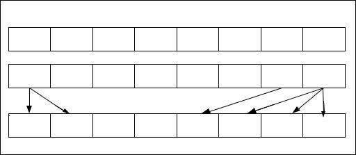
INSTRUCTION SET REFERENCE, N-Z
endif
}
00
+ + ))+ + + + + +
00
+ + + + + + ))+ +
00
+ + + + ))+ + + +
|
|
Figure 4-6. PSHUB with 64-Bit Operands |
Intel C/C++ Compiler Intrinsic Equivalent |
||
PSHUFB |
__m64 _mm_shuffle_pi8 (__m64 a, __m64 b) |
|
PSHUFB |
__m128i _mm_shufflehi_epi16(__m128i a, int n) |
|
Protected Mode Exceptions |
||
#GP(0) |
|
If a memory operand effective address is outside the CS, DS, |
|
|
ES, FS or GS segments. |
|
|
(128-bit operations only) If not aligned on 16-byte boundary, |
|
|
regardless of segment. |
#SS(0) |
|
If a memory operand effective address is outside the SS |
|
|
segment limit. |
#PF(fault-code) |
If a page fault occurs. |
|
#UD |
|
If CR0.EM = 1. |
|
|
(128-bit operations only) If CR4.OSFXSR(bit 9) = 0. |
|
|
If CPUID.SSSE3(ECX bit 9) = 0. |
#NM |
|
If TS bit in CR0 is set. |
#MF |
|
(64-bit operations only) If there is a pending x87 FPU exception. |
#AC(0) |
|
(64-bit operations only) If alignment checking is enabled and |
|
|
unaligned memory reference is made while the current privilege |
|
|
level is 3. |
4-150 Vol. 2B
|
INSTRUCTION SET REFERENCE, N-Z |
Real Mode Exceptions |
|
#GP(0) |
If any part of the operand lies outside of the effective address |
|
space from 0 to 0FFFFH. |
|
(128-bit operations only) If not aligned on 16-byte boundary, |
|
regardless of segment. |
#UD |
If CR0.EM = 1. |
|
(128-bit operations only) If CR4.OSFXSR(bit 9) = 0. |
|
If CPUID.SSSE3(ECX bit 9) = 0. |
#NM |
If TS bit in CR0 is set. |
#MF |
(64-bit operations only) If there is a pending x87 FPU exception. |
Virtual 8086 Mode Exceptions
Same exceptions as in Real Address Mode.
#PF(fault-code) |
If a page fault occurs. |
#AC(0) |
(64-bit operations only) If alignment checking is enabled and |
|
unaligned memory reference is made. |
Compatibility Mode Exceptions
Same as for protected mode exceptions.
64-Bit Mode Exceptions
#SS(0) |
If a memory address referencing the SS segment is in a non- |
|
canonical form. |
#GP(0) |
If the memory address is in a non-canonical form. |
|
(128-bit operations only) If memory operand is not aligned on a |
|
16-byte boundary, regardless of segment. |
#UD |
If CR0.EM[bit 2] = 1. |
|
(128-bit operations only) If CR4.OSFXSR[bit 9] = 0. |
|
If CPUID.01H:ECX.SSSE3[bit 9] = 0. |
#NM |
If CR0.TS[bit 3] = 1. |
#MF |
(64-bit operations only) If there is a pending x87 FPU exception. |
#PF(fault-code) |
If a page fault occurs. |
#AC(0) |
(64-bit operations only) If alignment checking is enabled and an |
|
unaligned memory reference is made while the current privilege |
|
level is 3. |
Vol. 2B 4-151

INSTRUCTION SET REFERENCE, N-Z
PSHUFD—Shuffle Packed Doublewords
|
|
64-Bit |
Compat/ |
|
Opcode |
Instruction |
Mode |
Leg Mode |
Description |
66 0F 70 /r ib |
PSHUFD xmm1, |
Valid |
Valid |
Shuffle the doublewords in |
|
xmm2/m128, imm8 |
|
|
xmm2/m128 based on the |
|
|
|
|
encoding in imm8 and |
|
|
|
|
store the result in xmm1. |
|
|
|
|
|
Description
Copies doublewords from source operand (second operand) and inserts them in the destination operand (first operand) at the locations selected with the order operand (third operand). Figure 4-7 shows the operation of the PSHUFD instruction and the encoding of the order operand. Each 2-bit field in the order operand selects the contents of one doubleword location in the destination operand. For example, bits 0 and 1 of the order operand select the contents of doubleword 0 of the destination operand. The encoding of bits 0 and 1 of the order operand (see the field encoding in Figure 4-7) determines which doubleword from the source operand will be copied to doubleword 0 of the destination operand.
SRC |
X3 |
X2 |
X1 |
X0 |
|
|
|
|
|
DEST |
Y3 |
|
Y2 |
|
|
Y1 |
|
Y0 |
|
|
|||
|
|
|
|
|
|
|
|
|
|
|
|
|
00B - X0 |
|
ORDER |
|
|
|
|
|
|
|
|
|
Encoding |
||
|
|
|
|
|
|
|
|
|
|
||||
|
|
|
|
|
|
|
|
|
of Fields in |
01B - X1 |
|||
|
|
|
|
|
|
|
|
|
|
|
ORDER |
10B - X2 |
|
|
7 |
6 5 |
4 |
3 |
2 1 |
0 |
|||||||
|
Operand |
11B - X3 |
|||||||||||
|
|
|
|
|
|
|
|
|
|
|
|||
Figure 4-7. PSHUFD Instruction Operation
The source operand can be an XMM register or a 128-bit memory location. The destination operand is an XMM register. The order operand is an 8-bit immediate. Note that this instruction permits a doubleword in the source operand to be copied to more than one doubleword location in the destination operand.
In 64-bit mode, using a REX prefix in the form of REX.R permits this instruction to access additional registers (XMM8-XMM15).
4-152 Vol. 2B
INSTRUCTION SET REFERENCE, N-Z
Operation
DEST[31:0] ← (SRC >> (ORDER[1:0] 32))[31:0];
DEST[63:32] ← (SRC >> (ORDER[3:2] 32))[31:0];
DEST[95:64] ← (SRC >> (ORDER[5:4] 32))[31:0];
DEST[127:96] ← (SRC >> (ORDER[7:6] 32))[31:0];
Intel C/C++ Compiler Intrinsic Equivalent
PSHUFD __m128i _mm_shuffle_epi32(__m128i a, int n)
Flags Affected
None.
Numeric Exceptions
None.
Protected Mode Exceptions
#GP(0) |
If a memory operand effective address is outside the CS, DS, |
|
ES, FS, or GS segment limit. |
|
If a memory operand is not aligned on a 16-byte boundary, |
|
regardless of segment. |
#SS(0) |
If a memory operand effective address is outside the SS |
|
segment limit. |
#UD |
If CR0.EM[bit 2] = 1. |
|
If CR4.OSFXSR[bit 9] = 0. |
|
If CPUID.01H:EDX.SSE2[bit 26] = 0. |
#NM |
If CR0.TS[bit 3] = 1. |
#PF(fault-code) |
If a page fault occurs. |
Real-Address Mode Exceptions
#GP(0) |
If a memory operand is not aligned on a 16-byte boundary, |
|
regardless of segment. |
|
If any part of the operand lies outside of the effective address |
|
space from 0 to FFFFH. |
#UD |
If CR0.EM[bit 2] = 1. |
|
If CR4.OSFXSR[bit 9] = 0. |
|
If CPUID.01H:EDX.SSE2[bit 26] = 0. |
#NM |
If CR0.TS[bit 3] = 1. |
Vol. 2B 4-153
INSTRUCTION SET REFERENCE, N-Z
Virtual-8086 Mode Exceptions
Same exceptions as in Real Address Mode #PF(fault-code) For a page fault.
Compatibility Mode Exceptions
Same as for protected mode exceptions.
64-Bit Mode Exceptions
#SS(0) |
If a memory address referencing the SS segment is in a non- |
|
canonical form. |
#GP(0) |
If the memory address is in a non-canonical form. |
|
If memory operand is not aligned on a 16-byte boundary, |
|
regardless of segment. |
#UD |
If CR0.EM[bit 2] = 1. |
|
If CR4.OSFXSR[bit 9] = 0. |
|
If CPUID.01H:EDX.SSE2[bit 26] = 0. |
#NM |
If CR0.TS[bit 3] = 1. |
#PF(fault-code) |
If a page fault occurs. |
4-154 Vol. 2B
INSTRUCTION SET REFERENCE, N-Z
PSHUFHW—Shuffle Packed High Words
|
|
64-Bit |
Compat/ |
|
Opcode |
Instruction |
Mode |
Leg Mode |
Description |
F3 0F 70 /r ib |
PSHUFHW xmm1, xmm2/ |
Valid |
Valid |
Shuffle the high words in |
|
m128, imm8 |
|
|
xmm2/m128 based on |
|
|
|
|
the encoding in imm8 and |
|
|
|
|
store the result in xmm1. |
|
|
|
|
|
Description
Copies words from the high quadword of the source operand (second operand) and inserts them in the high quadword of the destination operand (first operand) at word locations selected with the order operand (third operand). This operation is similar to the operation used by the PSHUFD instruction, which is illustrated in Figure 4-7. For the PSHUFHW instruction, each 2-bit field in the order operand selects the contents of one word location in the high quadword of the destination operand. The binary encodings of the order operand fields select words (0, 1, 2 or 3, 4) from the high quadword of the source operand to be copied to the destination operand. The low quadword of the source operand is copied to the low quadword of the destination operand.
The source operand can be an XMM register or a 128-bit memory location. The destination operand is an XMM register. The order operand is an 8-bit immediate. Note that this instruction permits a word in the high quadword of the source operand to be copied to more than one word location in the high quadword of the destination operand.
In 64-bit mode, using a REX prefix in the form of REX.R permits this instruction to access additional registers (XMM8-XMM15).
Operation
DEST[63:0] ← SRC[63:0];
DEST[79:64] ← (SRC >> (ORDER[1:0] 16))[79:64];
DEST[95:80] ← (SRC >> (ORDER[3:2] 16))[79:64];
DEST[111:96] ← (SRC >> (ORDER[5:4] 16))[79:64];
DEST[127:112] ← (SRC >> (ORDER[7:6] 16))[79:64];
Intel C/C++ Compiler Intrinsic Equivalent
PSHUFHW |
__m128i _mm_shufflehi_epi16(__m128i a, int n) |
Flags Affected
None.
Vol. 2B 4-155
INSTRUCTION SET REFERENCE, N-Z
Numeric Exceptions
None.
Protected Mode Exceptions
#GP(0) |
If a memory operand effective address is outside the CS, DS, |
|
ES, FS, or GS segment limit. |
|
If a memory operand is not aligned on a 16-byte boundary, |
|
regardless of segment. |
#SS(0) |
If a memory operand effective address is outside the SS |
|
segment limit. |
#UD |
If CR0.EM[bit 2] = 1. |
|
If CR4.OSFXSR[bit 9] = 0. |
|
If CPUID.01H:EDX.SSE2[bit 26] = 0. |
#NM |
If CR0.TS[bit 3] = 1. |
#PF(fault-code) |
If a page fault occurs. |
Real-Address Mode Exceptions
#GP(0) |
If a memory operand is not aligned on a 16-byte boundary, |
|
regardless of segment. |
|
If any part of the operand lies outside of the effective address |
|
space from 0 to FFFFH. |
#UD |
If CR0.EM[bit 2] = 1. |
|
If CR4.OSFXSR[bit 9] = 0. |
|
If CPUID.01H:EDX.SSE2[bit 26] = 0. |
#NM |
If CR0.TS[bit 3] = 1. |
Virtual-8086 Mode Exceptions
Same exceptions as in Real Address Mode #PF(fault-code) For a page fault.
Compatibility Mode Exceptions
Same as for protected mode exceptions.
64-Bit Mode Exceptions
#SS(0) |
If a memory address referencing the SS segment is in a non- |
|
canonical form. |
#GP(0) |
If the memory address is in a non-canonical form. |
|
If memory operand is not aligned on a 16-byte boundary, |
|
regardless of segment. |
4-156 Vol. 2B
|
INSTRUCTION SET REFERENCE, N-Z |
#UD |
If CR0.EM[bit 2] = 1. |
|
If CR4.OSFXSR[bit 9] = 0. |
|
If CPUID.01H:EDX.SSE2[bit 26] = 0. |
#NM |
If CR0.TS[bit 3] = 1. |
#PF(fault-code) |
If a page fault occurs. |
Vol. 2B 4-157
INSTRUCTION SET REFERENCE, N-Z
PSHUFLW—Shuffle Packed Low Words
|
|
64-Bit |
Compat/ |
|
Opcode |
Instruction |
Mode |
Leg Mode |
Description |
F2 0F 70 /r ib |
PSHUFLW xmm1, |
Valid |
Valid |
Shuffle the low words in |
|
xmm2/m128, imm8 |
|
|
xmm2/m128 based on the |
|
|
|
|
encoding in imm8 and store |
|
|
|
|
the result in xmm1. |
|
|
|
|
|
Description
Copies words from the low quadword of the source operand (second operand) and inserts them in the low quadword of the destination operand (first operand) at word locations selected with the order operand (third operand). This operation is similar to the operation used by the PSHUFD instruction, which is illustrated in Figure 4-7. For the PSHUFLW instruction, each 2-bit field in the order operand selects the contents of one word location in the low quadword of the destination operand. The binary encodings of the order operand fields select words (0, 1, 2, or 3) from the low quadword of the source operand to be copied to the destination operand. The high quadword of the source operand is copied to the high quadword of the destination operand.
The source operand can be an XMM register or a 128-bit memory location. The destination operand is an XMM register. The order operand is an 8-bit immediate. Note that this instruction permits a word in the low quadword of the source operand to be copied to more than one word location in the low quadword of the destination operand.
In 64-bit mode, using a REX prefix in the form of REX.R permits this instruction to access additional registers (XMM8-XMM15).
Operation
DEST[15:0] ← (SRC >> (ORDER[1:0] 16))[15:0];
DEST[31:16] ← (SRC >> (ORDER[3:2] 16))[15:0];
DEST[47:32] ← (SRC >> (ORDER[5:4] 16))[15:0];
DEST[63:48] ← (SRC >> (ORDER[7:6] 16))[15:0];
DEST[127:64] ← SRC[127:64];
Intel C/C++ Compiler Intrinsic Equivalent
PSHUFLW |
__m128i _mm_shufflelo_epi16(__m128i a, int n) |
Flags Affected
None.
4-158 Vol. 2B
INSTRUCTION SET REFERENCE, N-Z
Numeric Exceptions
None.
Protected Mode Exceptions
#GP(0) |
If a memory operand effective address is outside the CS, DS, |
|
ES, FS, or GS segment limit. |
|
If a memory operand is not aligned on a 16-byte boundary, |
|
regardless of segment. |
#SS(0) |
If a memory operand effective address is outside the SS |
|
segment limit. |
#UD |
If CR0.EM[bit 2] = 1. |
|
If CR4.OSFXSR[bit 9] = 0. |
|
If CPUID.01H:EDX.SSE2[bit 26] = 0. |
#NM |
If CR0.TS[bit 3] = 1. |
#PF(fault-code) |
If a page fault occurs. |
Real-Address Mode Exceptions
#GP(0) |
If a memory operand is not aligned on a 16-byte boundary, |
|
regardless of segment. |
|
If any part of the operand lies outside of the effective address |
|
space from 0 to FFFFH. |
#UD |
If CR0.EM[bit 2] = 1. |
|
If CR4.OSFXSR[bit 9] = 0. |
|
If CPUID.01H:EDX.SSE2[bit 26] = 0. |
#NM |
If CR0.TS[bit 3] = 1. |
Virtual-8086 Mode Exceptions
Same exceptions as in Real Address Mode #PF(fault-code) For a page fault.
Compatibility Mode Exceptions
Same as for protected mode exceptions.
64-Bit Mode Exceptions
#SS(0) |
If a memory address referencing the SS segment is in a non- |
|
canonical form. |
#GP(0) |
If the memory address is in a non-canonical form. |
|
If memory operand is not aligned on a 16-byte boundary, |
|
regardless of segment. |
Vol. 2B 4-159
INSTRUCTION SET REFERENCE, N-Z
#UD |
If CR0.EM[bit 2] = 1. |
|
If CR4.OSFXSR[bit 9] = 0. |
|
If CPUID.01H:EDX.SSE2[bit 26] = 0. |
#NM |
If CR0.TS[bit 3] = 1. |
#PF(fault-code) |
If a page fault occurs. |
4-160 Vol. 2B
|
|
|
|
INSTRUCTION SET REFERENCE, N-Z |
PSHUFW—Shuffle Packed Words |
|
|
||
|
|
|
|
|
|
|
64-Bit |
Compat/ |
|
Opcode |
Instruction |
Mode |
Leg Mode |
Description |
0F 70 /r |
PSHUFW mm1, |
Valid |
Valid |
Shuffle the words in mm2/m64 |
ib |
mm2/m64, imm8 |
|
|
based on the encoding in imm8 and |
|
|
|
|
store the result in mm1. |
|
|
|
|
|
Description
Copies words from the source operand (second operand) and inserts them in the destination operand (first operand) at word locations selected with the order operand (third operand). This operation is similar to the operation used by the PSHUFD instruction, which is illustrated in Figure 4-7. For the PSHUFW instruction, each 2-bit field in the order operand selects the contents of one word location in the destination operand. The encodings of the order operand fields select words from the source operand to be copied to the destination operand.
The source operand can be an MMX technology register or a 64-bit memory location. The destination operand is an MMX technology register. The order operand is an 8-bit immediate. Note that this instruction permits a word in the source operand to be copied to more than one word location in the destination operand.
In 64-bit mode, using a REX prefix in the form of REX.R permits this instruction to access additional registers (XMM8-XMM15).
Operation
DEST[15:0] ¨ (SRC >> (ORDER[1:0] * 16))[15:0];
DEST[31:16] ¨ (SRC >> (ORDER[3:2] * 16))[15:0];
DEST[47:32] ¨ (SRC >> (ORDER[5:4] * 16))[15:0];
DEST[63:48] ¨ (SRC >> (ORDER[7:6] * 16))[15:0];
Intel C/C++ Compiler Intrinsic Equivalent
PSHUFW __m64 _mm_shuffle_pi16(__m64 a, int n)
Flags Affected
None.
Numeric Exceptions
None.
Vol. 2B 4-161
INSTRUCTION SET REFERENCE, N-Z
Protected Mode Exceptions
#GP(0) |
If a memory operand effective address is outside the CS, DS, |
|
ES, FS, or GS segment limit. |
#SS(0) |
If a memory operand effective address is outside the SS |
|
segment limit. |
#UD |
If CR0.EM[bit 2] = 1. |
#NM |
If CR0.TS[bit 3] = 1. |
#MF |
If there is a pending x87 FPU exception. |
#PF(fault-code) |
If a page fault occurs. |
#AC(0) |
If alignment checking is enabled and an unaligned memory |
|
reference is made while the current privilege level is 3. |
Real-Address Mode Exceptions
#GP(0) |
If any part of the operand lies outside of the effective address |
|
space from 0 to FFFFH. |
#UD |
If CR0.EM[bit 2] = 1. |
#NM |
If CR0.TS[bit 3] = 1. |
#MF |
If there is a pending x87 FPU exception. |
Virtual-8086 Mode Exceptions
Same exceptions as in Real Address Mode
#PF(fault-code) |
For a page fault. |
#AC(0) |
If alignment checking is enabled and an unaligned memory |
|
reference is made. |
Compatibility Mode Exceptions
Same as for protected mode exceptions.
64-Bit Mode Exceptions
#SS(0) |
If a memory address referencing the SS segment is in a non- |
|
canonical form. |
#GP(0) |
If the memory address is in a non-canonical form. |
#UD |
If CR0.EM[bit 2] = 1. |
#NM |
If CR0.TS[bit 3] = 1. |
#MF |
If there is a pending x87 FPU exception. |
#PF(fault-code) |
If a page fault occurs. |
#AC(0) |
If alignment checking is enabled and an unaligned memory |
|
reference is made while the current privilege level is 3. |
4-162 Vol. 2B
|
|
|
|
|
INSTRUCTION SET REFERENCE, N-Z |
PSIGNB/PSIGNW/PSIGND — Packed SIGN |
|
||||
|
|
|
|
|
|
|
|
|
64-Bit |
Compat/ |
|
Opcode |
Instruction |
Mode |
Leg Mode |
Description |
|
0F 38 |
08 /r |
PSIGNB mm1, |
Valid |
Valid |
Negate packed byte integers in mm1 |
|
|
mm2/m64 |
|
|
if the corresponding sign in |
|
|
|
|
|
mm2/m64 is less than zero. |
66 0F |
38 08 |
PSIGNB |
Valid |
Valid |
Negate packed byte integers in |
/r |
|
xmm1, |
|
|
xmm1 if the corresponding sign in |
|
|
xmm2/m128 |
|
|
xmm2/m128 is less than zero. |
0F 38 |
09 /r |
PSIGNW |
|
|
Negate packed 16-bit integers in |
Valid |
Valid |
||||
|
|
mm1, |
|
|
mm1 if the corresponding sign in |
|
|
mm2/m64 |
|
|
mm2/m64 is less than zero. |
66 0F |
38 09 |
PSIGNW |
Valid |
Valid |
Negate packed 16-bit integers in |
/r |
|
xmm1, |
|
|
xmm1 if the corresponding sign in |
|
|
xmm2/m128 |
|
|
xmm2/m128 is less than zero. |
0F 38 |
0A /r |
PSIGND mm1, |
|
|
Negate packed doubleword integers |
Valid |
Valid |
||||
|
|
mm2/m64 |
|
|
in mm1 if the corresponding sign in |
|
|
|
|
|
mm2/m64 is less than zero. |
66 0F |
38 0A |
PSIGND |
Valid |
Valid |
Negate packed doubleword integers |
/r |
|
xmm1, |
|
|
in xmm1 if the corresponding sign in |
|
|
xmm2/m128 |
|
|
xmm2/m128 is less than zero. |
|
|
|
|
|
|
Description
PSIGNB/PSIGNW/PSIGND negates each data element of the destination operand (the first operand) if the sign of the corresponding data element in the source operand (the second operand) is less than zero. If the sign of a data element in the source operand is positive, the corresponding data element in the destination operand is unchanged. If a data element in the source operand is zero, the corresponding data element in the destination operand is set to zero.
PSIGNB operates on signed bytes. PSIGNW operates on 16-bit signed words. PSIGND operates on signed 32-bit integers. Both operands can be MMX register or XMM registers. When the source operand is a 128bit memory operand, the operand must be aligned on a 16-byte boundary or a general-protection exception (#GP) will be generated.
In 64-bit mode, use the REX prefix to access additional registers.
Operation
PSIGNB with 64 bit operands: if (SRC[7..0] < 0 )
DEST[7...0] <- Neg(DEST[7...0]) else if(SRC[7..0] == 0 )
Vol. 2B 4-163
INSTRUCTION SET REFERENCE, N-Z
DEST[7...0] <- 0 else if(SRC[7..0] > 0 )
DEST[7...0] <- DEST[7...0]
Repeat operation for 2nd through 7th bytes
if (SRC[63..56] < 0 )
DEST[63...56] <- Neg(DEST[63...56]) else if(SRC[63.. 56] == 0 )
DEST[63...56] <- 0 else if(SRC[63.. 56] > 0 )
DEST[63...56] <- DEST[63...56]
PSIGNB with 128 bit operands: if (SRC[7..0] < 0 )
DEST[7...0] <- Neg(DEST[7...0]) else if(SRC[7..0] == 0 )
DEST[7...0] <- 0 else if(SRC[7..0] > 0 )
DEST[7...0] <- DEST[7...0]
Repeat operation for 2nd through 15th bytes if (SRC[127..120] < 0 )
DEST[127...120] <- Neg(DEST[127...120]) else if(SRC[127.. 120] == 0 )
DEST[127...120] <- 0 else if(SRC[127.. 120] > 0 )
DEST[127...120] <- DEST[127...120]
PSIGNW with 64 bit operands: if (SRC[15..0] < 0 )
DEST[15...0] <- Neg(DEST[15...0]) else if(SRC[15..0] == 0 )
DEST[15...0] <- 0 else if(SRC[15..0] > 0 )
DEST[15...0] <- DEST[15...0]
Repeat operation for 2nd through 3rd words if (SRC[63..48] < 0 )
DEST[63...48] <- Neg(DEST[63...48]) else if(SRC[63..48] == 0 )
DEST[63...48] <- 0 else if(SRC[63..48] > 0 )
DEST[63...48] <- DEST[63...48]
PSIGNW with 128 bit operands: if (SRC[15..0] < 0 )
4-164 Vol. 2B
INSTRUCTION SET REFERENCE, N-Z
DEST[15...0] <- Neg(DEST[15...0]) else if(SRC[15..0] == 0 )
DEST[15...0] <- 0 else if(SRC[15..0] > 0 )
DEST[15...0] <- DEST[15...0]
Repeat operation for 2nd through 7th words if (SRC[127..112] < 0 )
DEST[127...112] <- Neg(DEST[127...112]) else if(SRC[127.. 112] == 0 )
DEST[127...112] <- 0 else if(SRC[127.. 112] > 0 )
DEST[127...112] <- DEST[127...112]
PSIGND with 64 bit operands: if (SRC[31..0] < 0 )
DEST[31...0] <- Neg(DEST[31...0]) else if(SRC[31..0] == 0 )
DEST[31...0] <- 0 else if(SRC[31..0] > 0 )
DEST[31...0] <- DEST[31...0] if (SRC[63..32] < 0 )
DEST[63...32] <- Neg(DEST[63...32]) else if(SRC[63.. 32] == 0 )
DEST[63...32] <- 0 else if(SRC[63.. 32] > 0 )
DEST[63...32] <- DEST[63...32]
PSIGND with 128 bit operands: if (SRC[31..0] < 0 )
DEST[31...0] <- Neg(DEST[31...0]) else if(SRC[31..0] == 0 )
DEST[31...0] <- 0 else if(SRC[31..0] > 0 )
DEST[31...0] <- DEST[31...0]
Repeat operation for 2nd through 3rd double words if (SRC[127..96] < 0 )
DEST[127...96] <- Neg(DEST[127...96]) else if(SRC[127.. 96] == 0 )
DEST[127...96] <- 0 else if(SRC[127.. 96] > 0 )
DEST[127...96] <- DEST[127...96]
Vol. 2B 4-165
INSTRUCTION SET REFERENCE, N-Z
Intel C/C++ Compiler Intrinsic Equivalent
PSIGNB |
__m64 |
_mm_sign_pi8 (__m64 a, __m64 b) |
PSIGNB |
__m128i _mm_sign_epi8 (__m128i a, __m128i b) |
|
PSIGNW |
__m64 |
_mm_sign_pi16 (__m64 a, __m64 b) |
PSIGNW |
__m128i _mm_sign_epi16 (__m128i a, __m128i b) |
|
PSIGND |
__m64 |
_mm_sign_pi32 (__m64 a, __m64 b) |
PSIGND |
__m128i _mm_sign_epi32 (__m128i a, __m128i b) |
|
Protected Mode Exceptions
#GP(0) |
If a memory operand effective address is outside the CS, DS, |
|
ES, FS or GS segments. |
|
(128-bit operations only) If not aligned on 16-byte boundary, |
|
regardless of segment. |
#SS(0) |
If a memory operand effective address is outside the SS |
|
segment limit. |
#PF(fault-code) |
If a page fault occurs. |
#UD |
If CR0.EM = 1. |
|
(128-bit operations only) If CR4.OSFXSR(bit 9) = 0. |
|
If CPUID.SSSE3(ECX bit 9) = 0. |
#NM |
If TS bit in CR0 is set. |
#MF |
(64-bit operations only) If there is a pending x87 FPU exception. |
#AC(0) |
(64-bit operations only) If alignment checking is enabled and |
|
unaligned memory reference is made while the current privilege |
|
level is 3. |
Real Mode Exceptions
#GP(0) |
If any part of the operand lies outside of the effective address |
|
space from 0 to 0FFFFH. |
|
(128-bit operations only) If not aligned on 16-byte boundary, |
|
regardless of segment. |
#UD |
(128-bit operations only) If CR0.EM = 1. If CR4.OSFXSR(bit 9) |
|
= 0. |
|
If CPUID.SSSE3(ECX bit 9) = 0. |
#NM |
If TS bit in CR0 is set. |
#MF |
(64-bit operations only) If there is a pending x87 FPU exception. |
4-166 Vol. 2B
INSTRUCTION SET REFERENCE, N-Z
Virtual 8086 Mode Exceptions
Same exceptions as in Real Address Mode.
#PF(fault-code) |
If a page fault occurs. |
#AC(0) |
(64-bit operations only) If alignment checking is enabled and |
|
unaligned memory reference is made. |
Compatibility Mode Exceptions
Same as for protected mode exceptions.
64-Bit Mode Exceptions
#SS(0) |
If a memory address referencing the SS segment is in a non- |
|
canonical form. |
#GP(0) |
If the memory address is in a non-canonical form. |
|
(128-bit operations only) If memory operand is not aligned on a |
|
16-byte boundary, regardless of segment. |
#UD |
If CR0.EM[bit 2] = 1. |
|
(128-bit operations only) If CR4.OSFXSR[bit 9] = 0. |
|
If CPUID.01H:ECX.SSSE3[bit 9] = 0. |
#NM |
If CR0.TS[bit 3] = 1. |
#MF |
(64-bit operations only) If there is a pending x87 FPU exception. |
#PF(fault-code) |
If a page fault occurs. |
#AC(0) |
(64-bit operations only) If alignment checking is enabled and an |
|
unaligned memory reference is made while the current privilege |
|
level is 3. |
Vol. 2B 4-167
INSTRUCTION SET REFERENCE, N-Z
PSLLDQ—Shift Double Quadword Left Logical
|
|
|
Compat/ |
|
|
|
64-Bit |
Leg |
|
Opcode |
Instruction |
Mode |
Mode |
Description |
66 0F 73 /7 ib |
PSLLDQ xmm1, |
Valid |
Valid |
Shift xmm1 left by imm8 bytes |
|
imm8 |
|
|
while shifting in 0s. |
|
|
|
|
|
Description
Shifts the destination operand (first operand) to the left by the number of bytes specified in the count operand (second operand). The empty low-order bytes are cleared (set to all 0s). If the value specified by the count operand is greater than 15, the destination operand is set to all 0s. The destination operand is an XMM register. The count operand is an 8-bit immediate.
Operation
TEMP ← COUNT;
IF (TEMP > 15) THEN TEMP ← 16; FI;
DEST ← DEST << (TEMP 8);
Intel C/C++ Compiler Intrinsic Equivalent
PSLLDQ __m128i _mm_slli_si128 ( __m128i a, int imm)
Flags Affected
None.
Numeric Exceptions
None.
Protected Mode Exceptions
#UD |
If CR0.EM[bit 2] = 1. |
|
If CR4.OSFXSR[bit 9] = 0. |
|
If CPUID.01H:EDX.SSE2[bit 26] = 0. |
#NM |
If CR0.TS[bit 3] = 1. |
Real-Address Mode Exceptions
Same exceptions as in Protected Mode.
4-168 Vol. 2B
INSTRUCTION SET REFERENCE, N-Z
Virtual-8086 Mode Exceptions
Same exceptions as in Protected Mode.
Compatibility Mode Exceptions
Same exceptions as in Protected Mode.
64-Bit Mode Exceptions
Same exceptions as in Protected Mode.
Vol. 2B 4-169
INSTRUCTION SET REFERENCE, N-Z
PSLLW/PSLLD/PSLLQ—Shift Packed Data Left Logical
|
|
|
64- |
|
|
|
|
|
Bit |
Compat/ |
|
Opcode |
Instruction |
Mode |
Leg Mode |
Description |
|
0F F1 /r |
PSLLW mm, |
Valid |
Valid |
Shift words in mm left |
|
|
|
mm/m64 |
|
|
mm/m64 while shifting in 0s. |
66 0F |
F1 /r |
PSLLW xmm1, |
Valid |
Valid |
Shift words in xmm1 left by |
|
|
xmm2/m128 |
|
|
xmm2/m128 while shifting in |
|
|
|
|
|
0s. |
0F 71 |
/6 ib |
PSLLW xmm1, imm8 |
Valid |
Valid |
Shift words in mm left by imm8 |
|
|
|
|
|
while shifting in 0s. |
66 0F |
71 /6 ib |
PSLLW xmm1, imm8 |
Valid |
Valid |
Shift words in xmm1 left by |
|
|
|
|
|
imm8 while shifting in 0s. |
0F F2 /r |
PSLLD mm, |
Valid |
Valid |
Shift doublewords in mm left |
|
|
|
mm/m64 |
|
|
by mm/m64 while shifting in |
|
|
|
|
|
0s. |
66 0F |
F2 /r |
PSLLD xmm1, |
Valid |
Valid |
Shift doublewords in xmm1 left |
|
|
xmm2/m128 |
|
|
by xmm2/m128 while shifting |
|
|
|
|
|
in 0s. |
0F 72 |
/6 ib |
PSLLD mm, imm8 |
Valid |
Valid |
Shift doublewords in mm left |
|
|
|
|
|
by imm8 while shifting in 0s. |
66 0F |
72 /6 ib |
PSLLD xmm1, imm8 |
Valid |
Valid |
Shift doublewords in xmm1 left |
|
|
|
|
|
by imm8 while shifting in 0s. |
0F F3 /r |
PSLLQ mm, |
Valid |
Valid |
Shift quadword in mm left by |
|
|
|
mm/m64 |
|
|
mm/m64 while shifting in 0s. |
66 0F |
F3 /r |
PSLLQ xmm1, |
Valid |
Valid |
Shift quadwords in xmm1 left |
|
|
xmm2/m128 |
|
|
by xmm2/m128 while shifting |
|
|
|
|
|
in 0s. |
0F 73 |
/6 ib |
PSLLQ mm, imm8 |
Valid |
Valid |
Shift quadword in mm left by |
|
|
|
|
|
imm8 while shifting in 0s. |
66 0F |
73 /6 ib |
PSLLQ xmm1, imm8 |
Valid |
Valid |
Shift quadwords in xmm1 left |
|
|
|
|
|
by imm8 while shifting in 0s. |
|
|
|
|
|
|
Description
Shifts the bits in the individual data elements (words, doublewords, or quadword) in the destination operand (first operand) to the left by the number of bits specified in the count operand (second operand). As the bits in the data elements are shifted left, the empty low-order bits are cleared (set to 0). If the value specified by the count operand is greater than 15 (for words), 31 (for doublewords), or 63 (for a quadword), then the destination operand is set to all 0s. Figure 4-8 gives an example of shifting words in a 64-bit operand.
4-170 Vol. 2B

INSTRUCTION SET REFERENCE, N-Z
The destination operand may be an MMX technology register or an XMM register; the count operand can be either an MMX technology register or an 64-bit memory location, an XMM register or a 128-bit memory location, or an 8-bit immediate. Note that only the first 64-bits of a 128-bit count operand are checked to compute the count.
Pre-Shift |
|
X3 |
|
X2 |
|
X1 |
|
|
X0 |
|||||
DEST |
|
|
|
|
|
|||||||||
|
|
|
|
|
|
|
|
|
|
|
|
|
||
Shift Left |
|
|
|
|
|
|
|
|
|
|
|
|
|
|
with Zero |
|
|
|
|
|
|
|
|
|
|
|
|
|
|
Extension |
|
|
|
|
|
|
|
|
|
|
|
|
|
|
Post-Shift |
|
|
|
|
|
|
|
|
|
|
|
|
|
|
|
X3 << COUNT |
X2 << COUNT |
X1 << COUNT |
|
X0 << COUNT |
|||||||||
DEST |
|
|
||||||||||||
Figure 4-8. PSLLW, PSLLD, and PSLLQ Instruction Operation Using 64-bit Operand
The PSLLW instruction shifts each of the words in the destination operand to the left by the number of bits specified in the count operand; the PSLLD instruction shifts each of the doublewords in the destination operand; and the PSLLQ instruction shifts the quadword (or quadwords) in the destination operand.
In 64-bit mode, using a REX prefix in the form of REX.R permits this instruction to access additional registers (XMM8-XMM15).
Operation
PSLLW instruction with 64-bit operand: IF (COUNT > 15)
THEN
DEST[64:0] ← 0000000000000000H; ELSE
DEST[15:0] ← ZeroExtend(DEST[15:0] << COUNT); (* Repeat shift operation for 2nd and 3rd words *) DEST[63:48] ← ZeroExtend(DEST[63:48] << COUNT);
FI;
PSLLD instruction with 64-bit operand:
IF (COUNT > 31)
THEN
DEST[64:0] ← 0000000000000000H;
ELSE
DEST[31:0] ← ZeroExtend(DEST[31:0] << COUNT);
DEST[63:32] ← ZeroExtend(DEST[63:32] << COUNT);
FI;
PSLLQ instruction with 64-bit operand:
IF (COUNT > 63)
Vol. 2B 4-171
INSTRUCTION SET REFERENCE, N-Z
THEN
DEST[64:0] ← 0000000000000000H;
ELSE
DEST ← ZeroExtend(DEST << COUNT);
FI;
PSLLW instruction with 128-bit operand: COUNT ← COUNT_SOURCE[63:0];
IF (COUNT > 15) THEN
DEST[128:0] ← 00000000000000000000000000000000H; ELSE
DEST[15:0] ← ZeroExtend(DEST[15:0] << COUNT);
(* Repeat shift operation for 2nd through 7th words *) DEST[127:112] ← ZeroExtend(DEST[127:112] << COUNT);
FI;
PSLLD instruction with 128-bit operand: COUNT ← COUNT_SOURCE[63:0]; IF (COUNT > 31)
THEN
DEST[128:0] ← 00000000000000000000000000000000H; ELSE
DEST[31:0] ← ZeroExtend(DEST[31:0] << COUNT);
(* Repeat shift operation for 2nd and 3rd doublewords *) DEST[127:96] ← ZeroExtend(DEST[127:96] << COUNT);
FI;
PSLLQ instruction with 128-bit operand: COUNT ← COUNT_SOURCE[63:0];
IF (COUNT > 63) THEN
DEST[128:0] ← 00000000000000000000000000000000H; ELSE
DEST[63:0] ← ZeroExtend(DEST[63:0] << COUNT); DEST[127:64] ← ZeroExtend(DEST[127:64] << COUNT);
FI;
Intel C/C++ Compiler Intrinsic Equivalents
PSLLW |
__m64 |
_mm_slli_pi16 (__m64 m, int count) |
PSLLW |
__m64 |
_mm_sll_pi16(__m64 m, __m64 count) |
PSLLW |
__m128i _mm_slli_pi16(__m64 m, int count) |
|
PSLLW |
__m128i _mm_slli_pi16(__m128i m, __m128i count) |
|
4-172 Vol. 2B
|
|
INSTRUCTION SET REFERENCE, N-Z |
PSLLD |
__m64 |
_mm_slli_pi32(__m64 m, int count) |
PSLLD |
__m64 |
_mm_sll_pi32(__m64 m, __m64 count) |
PSLLD |
__m128i _mm_slli_epi32(__m128i m, int count) |
|
PSLLD |
__m128i _mm_sll_epi32(__m128i m, __m128i count) |
|
PSLLQ |
__m64 |
_mm_slli_si64(__m64 m, int count) |
PSLLQ |
__m64 |
_mm_sll_si64(__m64 m, __m64 count) |
PSLLQ |
__m128i _mm_slli_si64(__m128i m, int count) |
|
PSLLQ |
__m128i _mm_sll_si64(__m128i m, __m128i count) |
|
Flags Affected
None.
Numeric Exceptions
None.
Protected Mode Exceptions
#GP(0) |
If a memory operand effective address is outside the CS, DS, |
|
ES, FS, or GS segment limit. |
|
(128-bit operations only) If a memory operand is not aligned on |
|
a 16-byte boundary, regardless of segment. |
#SS(0) |
If a memory operand effective address is outside the SS |
|
segment limit. |
#UD |
If CR0.EM[bit 2] = 1. |
|
(128-bit operations only) If CR4.OSFXSR[bit 9] = 0. |
|
(128-bit operations only) If CPUID.01H:EDX.SSE2[bit 26] = 0. |
#NM |
If CR0.TS[bit 3] = 1. |
#MF |
(64-bit operations only) If there is a pending x87 FPU exception. |
#PF(fault-code) |
If a page fault occurs. |
#AC(0) |
(64-bit operations only) If alignment checking is enabled and an |
|
unaligned memory reference is made while the current privilege |
|
level is 3. |
Real-Address Mode Exceptions
#GP(0) |
(128-bit operations only) If a memory operand is not aligned on |
|
a 16-byte boundary, regardless of segment. |
|
If any part of the operand lies outside of the effective address |
|
space from 0 to FFFFH. |
Vol. 2B 4-173
INSTRUCTION SET REFERENCE, N-Z
#UD |
If CR0.EM[bit 2] = 1. |
|
(128-bit operations only) If CR4.OSFXSR[bit 9] = 0. |
|
(128-bit operations only) If CPUID.01H:EDX.SSE2[bit 26] = 0. |
#NM |
If CR0.TS[bit 3] = 1. |
#MF |
(64-bit operations only) If there is a pending x87 FPU exception. |
Virtual-8086 Mode Exceptions
Same exceptions as in Real Address Mode
#PF(fault-code) |
For a page fault. |
#AC(0) |
(64-bit operations only) If alignment checking is enabled and an |
|
unaligned memory reference is made. |
Compatibility Mode Exceptions
Same as for protected mode exceptions.
64-Bit Mode Exceptions
#SS(0) |
If a memory address referencing the SS segment is in a non- |
|
canonical form. |
#GP(0) |
If the memory address is in a non-canonical form. |
|
(128-bit operations only) If memory operand is not aligned on a |
|
16-byte boundary, regardless of segment. |
#UD |
If CR0.EM[bit 2] = 1. |
|
(128-bit operations only) If CR4.OSFXSR[bit 9] = 0. |
|
(128-bit operations only) If CPUID.01H:EDX.SSE2[bit 26] = 0. |
#NM |
If CR0.TS[bit 3] = 1. |
#MF |
(64-bit operations only) If there is a pending x87 FPU exception. |
#PF(fault-code) |
If a page fault occurs. |
#AC(0) |
(64-bit operations only) If alignment checking is enabled and an |
|
unaligned memory reference is made while the current privilege |
|
level is 3. |
4-174 Vol. 2B
|
|
|
|
INSTRUCTION SET REFERENCE, N-Z |
PSRAW/PSRAD—Shift Packed Data Right Arithmetic |
||||
|
|
|
|
|
|
|
64-Bit |
Compat/ |
|
Opcode |
Instruction |
Mode |
Leg Mode |
Description |
0F E1 /r |
PSRAW mm, |
Valid |
Valid |
Shift words in mm right by |
|
mm/m64 |
|
|
mm/m64 while shifting in sign |
|
|
|
|
bits. |
66 0F E1 /r |
PSRAW xmm1, |
Valid |
Valid |
Shift words in xmm1 right by |
|
xmm2/m128 |
|
|
xmm2/m128 while shifting in |
|
|
|
|
sign bits. |
0F 71 /4 ib |
PSRAW mm, |
Valid |
Valid |
Shift words in mm right by imm8 |
|
imm8 |
|
|
while shifting in sign bits |
66 0F 71 /4 ib |
PSRAW xmm1, |
Valid |
Valid |
Shift words in xmm1 right by |
|
imm8 |
|
|
imm8 while shifting in sign bits |
0F E2 /r |
PSRAD mm, |
Valid |
Valid |
Shift doublewords in mm right |
|
mm/m64 |
|
|
by mm/m64 while shifting in |
|
|
|
|
sign bits. |
66 0F E2 /r |
PSRAD xmm1, |
Valid |
Valid |
Shift doubleword in xmm1 right |
|
xmm2/m128 |
|
|
by xmm2 /m128 while shifting |
|
|
|
|
in sign bits. |
0F 72 /4 ib |
PSRAD mm, |
Valid |
Valid |
Shift doublewords in mm right |
|
imm8 |
|
|
by imm8 while shifting in sign |
|
|
|
|
bits. |
66 0F 72 /4 ib |
PSRAD xmm1, |
Valid |
Valid |
Shift doublewords in xmm1 right |
|
imm8 |
|
|
by imm8 while shifting in sign |
|
|
|
|
bits. |
|
|
|
|
|
Description
Shifts the bits in the individual data elements (words or doublewords) in the destination operand (first operand) to the right by the number of bits specified in the count operand (second operand). As the bits in the data elements are shifted right, the empty high-order bits are filled with the initial value of the sign bit of the data element. If the value specified by the count operand is greater than 15 (for words) or 31 (for doublewords), each destination data element is filled with the initial value of the sign bit of the element. (Figure 4-9 gives an example of shifting words in a 64-bit operand.)
Vol. 2B 4-175

INSTRUCTION SET REFERENCE, N-Z
Pre-Shift |
|
X3 |
|
X2 |
|
X1 |
|
X0 |
|
|||||
DEST |
|
|
|
|
|
|||||||||
|
|
|
|
|
|
|
|
|
|
|
|
|
||
Shift Right |
|
|
|
|
|
|
|
|
|
|
|
|
|
|
with Sign |
|
|
|
|
|
|
|
|
|
|
|
|
|
|
|
|
|
|
|
|
|
|
|
|
|
|
|
||
Extension |
|
|
|
|
|
|
|
|
|
|
|
|
|
|
Post-Shift |
|
|
|
|
|
|
|
|
|
|
|
|
|
|
|
X3 >> COUNT |
X2 >> COUNT |
X1 >> COUNT |
X0 >> COUNT |
|
|||||||||
DEST |
|
|
||||||||||||
Figure 4-9. PSRAW and PSRAD Instruction Operation Using a 64-bit Operand
The destination operand may be an MMX technology register or an XMM register; the count operand can be either an MMX technology register or an 64-bit memory location, an XMM register or a 128-bit memory location, or an 8-bit immediate. Note that only the first 64-bits of a 128-bit count operand are checked to compute the count.
The PSRAW instruction shifts each of the words in the destination operand to the right by the number of bits specified in the count operand, and the PSRAD instruction shifts each of the doublewords in the destination operand.
In 64-bit mode, using a REX prefix in the form of REX.R permits this instruction to access additional registers (XMM8-XMM15).
Operation
PSRAW instruction with 64-bit operand: IF (COUNT > 15)
THEN COUNT ← 16;
FI;
DEST[15:0] ← SignExtend(DEST[15:0] >> COUNT); (* Repeat shift operation for 2nd and 3rd words *) DEST[63:48] ← SignExtend(DEST[63:48] >> COUNT);
PSRAD instruction with 64-bit operand:
IF (COUNT > 31)
THEN COUNT ← 32;
FI;
DEST[31:0] ← SignExtend(DEST[31:0] >> COUNT);
DEST[63:32] ← SignExtend(DEST[63:32] >> COUNT);
PSRAW instruction with 128-bit operand:
COUNT ← COUNT_SOURCE[63:0];
4-176 Vol. 2B
INSTRUCTION SET REFERENCE, N-Z
IF (COUNT > 15)
THEN COUNT ← 16;
FI;
DEST[15:0] ← SignExtend(DEST[15:0] >> COUNT);
(* Repeat shift operation for 2nd through 7th words *) DEST[127:112] ← SignExtend(DEST[127:112] >> COUNT);
PSRAD instruction with 128-bit operand: COUNT ← COUNT_SOURCE[63:0];
IF (COUNT > 31)
THEN COUNT ← 32;
FI;
DEST[31:0] ← SignExtend(DEST[31:0] >> COUNT);
(* Repeat shift operation for 2nd and 3rd doublewords *) DEST[127:96] ← SignExtend(DEST[127:96] >>COUNT);
Intel C/C++ Compiler Intrinsic Equivalents
PSRAW |
__m64 |
_mm_srai_pi16 (__m64 m, int count) |
PSRAW |
__m64 |
_mm_sraw_pi16 (__m64 m, __m64 count) |
PSRAD |
__m64 |
_mm_srai_pi32 (__m64 m, int count) |
PSRAD |
__m64 |
_mm_sra_pi32 (__m64 m, __m64 count) |
PSRAW |
__m128i _mm_srai_epi16(__m128i m, int count) |
|
PSRAW |
__m128i _mm_sra_epi16(__m128i m, __m128i count)) |
|
PSRAD |
__m128i _mm_srai_epi32 (__m128i m, int count) |
|
PSRAD |
__m128i _mm_sra_epi32 (__m128i m, __m128i count) |
|
Flags Affected
None.
Numeric Exceptions
None.
Protected Mode Exceptions
#GP(0) |
If a memory operand effective address is outside the CS, DS, |
|
ES, FS, or GS segment limit. |
|
(128-bit operations only) If a memory operand is not aligned on |
|
a 16-byte boundary, regardless of segment. |
Vol. 2B 4-177
INSTRUCTION SET REFERENCE, N-Z
#SS(0) |
If a memory operand effective address is outside the SS |
|
segment limit. |
#UD |
If CR0.EM[bit 2] = 1. |
|
(128-bit operations only) If CR4.OSFXSR[bit 9] = 0. |
|
(128-bit operations only) If CPUID.01H:EDX.SSE2[bit 26] = 0. |
#NM |
If CR0.TS[bit 3] = 1. |
#MF |
(64-bit operations only) If there is a pending x87 FPU exception. |
#PF(fault-code) |
If a page fault occurs. |
#AC(0) |
(64-bit operations only) If alignment checking is enabled and an |
|
unaligned memory reference is made while the current privilege |
|
level is 3. |
Real-Address Mode Exceptions
#GP(0) |
(128-bit operations only) If a memory operand is not aligned on |
|
a 16-byte boundary, regardless of segment. |
|
If any part of the operand lies outside of the effective address |
|
space from 0 to FFFFH. |
#UD |
If CR0.EM[bit 2] = 1. |
|
(128-bit operations only) If CR4.OSFXSR[bit 9] = 0. |
|
(128-bit operations only) If CPUID.01H:EDX.SSE2[bit 26] = 0. |
#NM |
If CR0.TS[bit 3] = 1. |
#MF |
(64-bit operations only) If there is a pending x87 FPU exception. |
Virtual-8086 Mode Exceptions
Same exceptions as in Real Address Mode
#PF(fault-code) |
For a page fault. |
#AC(0) |
(64-bit operations only) If alignment checking is enabled and an |
|
unaligned memory reference is made. |
Compatibility Mode Exceptions
Same as for protected mode exceptions.
64-Bit Mode Exceptions
#SS(0) |
If a memory address referencing the SS segment is in a non- |
|
canonical form. |
#GP(0) |
If the memory address is in a non-canonical form. |
|
(128-bit operations only) If memory operand is not aligned on a |
|
16-byte boundary, regardless of segment. |
4-178 Vol. 2B
|
INSTRUCTION SET REFERENCE, N-Z |
#UD |
If CR0.EM[bit 2] = 1. |
|
(128-bit operations only) If CR4.OSFXSR[bit 9] = 0. |
|
(128-bit operations only) If CPUID.01H:EDX.SSE2[bit 26] = 0. |
#NM |
If CR0.TS[bit 3] = 1. |
#MF |
(64-bit operations only) If there is a pending x87 FPU exception. |
#PF(fault-code) |
If a page fault occurs. |
#AC(0) |
(64-bit operations only) If alignment checking is enabled and an |
|
unaligned memory reference is made while the current privilege |
|
level is 3. |
Vol. 2B 4-179
INSTRUCTION SET REFERENCE, N-Z
PSRLDQ—Shift Double Quadword Right Logical
|
|
64-Bit |
Compat/ |
|
Opcode |
Instruction |
Mode |
Leg Mode |
Description |
66 0F 73 /3 ib |
PSRLDQ |
Valid |
Valid |
Shift xmm1 right by imm8 while |
|
xmm1, imm8 |
|
|
shifting in 0s. |
|
|
|
|
|
Description
Shifts the destination operand (first operand) to the right by the number of bytes specified in the count operand (second operand). The empty high-order bytes are cleared (set to all 0s). If the value specified by the count operand is greater than 15, the destination operand is set to all 0s. The destination operand is an XMM register. The count operand is an 8-bit immediate.
In 64-bit mode, using a REX prefix in the form of REX.R permits this instruction to access additional registers (XMM8-XMM15).
Operation
TEMP ← COUNT;
IF (TEMP > 15) THEN TEMP ← 16; FI;
DEST ← DEST >> (temp 8);
Intel C/C++ Compiler Intrinsic Equivalents
PSRLDQ __m128i _mm_srli_si128 ( __m128i a, int imm)
Flags Affected
None.
Numeric Exceptions
None.
Protected Mode Exceptions
#UD |
If CR0.EM[bit 2] = 1. |
|
If CR4.OSFXSR[bit 9] = 0. |
|
If CPUID.01H:EDX.SSE2[bit 26] = 0. |
#NM |
If CR0.TS[bit 3] = 1. |
Real-Address Mode Exceptions
Same exceptions as in Protected Mode.
4-180 Vol. 2B
INSTRUCTION SET REFERENCE, N-Z
Virtual-8086 Mode Exceptions
Same exceptions as in Protected Mode.
Compatibility Mode Exceptions
Same exceptions as in Protected Mode.
64-Bit Mode Exceptions
Same exceptions as in Protected Mode.
Numeric Exceptions
None.
Vol. 2B 4-181
INSTRUCTION SET REFERENCE, N-Z
PSRLW/PSRLD/PSRLQ—Shift Packed Data Right Logical
|
|
|
|
Compat/ |
|
|
|
|
64-Bit |
Leg |
|
Opcode |
Instruction |
Mode |
Mode |
Description |
|
0F D1 /r |
PSRLW mm, |
Valid |
Valid |
Shift words in mm right by amount |
|
|
|
mm/m64 |
|
|
specified in mm/m64 while shifting in |
|
|
|
|
|
0s. |
66 0F |
D1 /r |
PSRLW xmm1, |
Valid |
Valid |
Shift words in xmm1 right by amount |
|
|
xmm2/m128 |
|
|
specified in xmm2/m128 while |
|
|
|
|
|
shifting in 0s. |
0F 71 |
/2 ib |
PSRLW mm, |
Valid |
Valid |
Shift words in mm right by imm8 |
|
|
imm8 |
|
|
while shifting in 0s. |
66 0F |
71 /2 |
PSRLW xmm1, |
Valid |
Valid |
Shift words in xmm1 right by imm8 |
ib |
|
imm8 |
|
|
while shifting in 0s. |
0F D2 /r |
PSRLD mm, |
Valid |
Valid |
Shift doublewords in mm right by |
|
|
|
mm/m64 |
|
|
amount specified in mm/m64 while |
|
|
|
|
|
shifting in 0s. |
66 0F |
D2 /r |
PSRLD xmm1, |
Valid |
Valid |
Shift doublewords in xmm1 right by |
|
|
xmm2/m128 |
|
|
amount specified in xmm2 /m128 |
|
|
|
|
|
while shifting in 0s. |
0F 72 |
/2 ib |
PSRLD mm, |
Valid |
Valid |
Shift doublewords in mm right by |
|
|
imm8 |
|
|
imm8 while shifting in 0s. |
66 0F |
72 /2 |
PSRLD xmm1, |
Valid |
Valid |
Shift doublewords in xmm1 right by |
ib |
|
imm8 |
|
|
imm8 while shifting in 0s. |
0F D3 /r |
PSRLQ mm, |
Valid |
Valid |
Shift mm right by amount specified in |
|
|
|
mm/m64 |
|
|
mm/m64 while shifting in 0s. |
66 0F |
D3 /r |
PSRLQ xmm1, |
Valid |
Valid |
Shift quadwords in xmm1 right by |
|
|
xmm2/m128 |
|
|
amount specified in xmm2/m128 |
|
|
|
|
|
while shifting in 0s. |
0F 73 |
/2 ib |
PSRLQ mm, |
Valid |
Valid |
Shift mm right by imm8 while |
|
|
imm8 |
|
|
shifting in 0s. |
66 0F |
73 /2 |
PSRLQ xmm1, |
Valid |
Valid |
Shift quadwords in xmm1 right by |
ib |
|
imm8 |
|
|
imm8 while shifting in 0s. |
|
|
|
|
|
|
Description
Shifts the bits in the individual data elements (words, doublewords, or quadword) in the destination operand (first operand) to the right by the number of bits specified in the count operand (second operand). As the bits in the data elements are shifted right, the empty high-order bits are cleared (set to 0). If the value specified by the count operand is greater than 15 (for words), 31 (for doublewords), or 63 (for a quadword), then the destination operand is set to all 0s. Figure 4-10 gives an example of shifting words in a 64-bit operand.
4-182 Vol. 2B
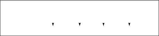
INSTRUCTION SET REFERENCE, N-Z
The destination operand may be an MMX technology register or an XMM register; the count operand can be either an MMX technology register or an 64-bit memory location, an XMM register or a 128-bit memory location, or an 8-bit immediate. Note that only the first 64-bits of a 128-bit count operand are checked to compute the count.
Pre-Shift |
|
X3 |
|
X2 |
|
X1 |
|
X0 |
|
|||||
DEST |
|
|
|
|
|
|||||||||
|
|
|
|
|
|
|
|
|
|
|
|
|
||
Shift Right |
|
|
|
|
|
|
|
|
|
|
|
|
|
|
with Zero |
|
|
|
|
|
|
|
|
|
|
|
|
|
|
|
|
|
|
|
|
|
|
|
|
|
|
|
||
Extension |
|
|
|
|
|
|
|
|
|
|
|
|
|
|
Post-Shift |
|
|
|
|
|
|
|
|
|
|
|
|
|
|
|
X3 >> COUNT |
X2 >> COUNT |
X1 >> COUNT |
X0 >> COUNT |
|
|||||||||
DEST |
|
|
||||||||||||
Figure 4-10. PSRLW, PSRLD, and PSRLQ Instruction Operation Using 64-bit Operand
The PSRLW instruction shifts each of the words in the destination operand to the right by the number of bits specified in the count operand; the PSRLD instruction shifts each of the doublewords in the destination operand; and the PSRLQ instruction shifts the quadword (or quadwords) in the destination operand.
In 64-bit mode, using a REX prefix in the form of REX.R permits this instruction to access additional registers (XMM8-XMM15).
Operation
PSRLW instruction with 64-bit operand: IF (COUNT > 15)
THEN
DEST[64:0] ← 0000000000000000H ELSE
DEST[15:0] ← ZeroExtend(DEST[15:0] >> COUNT); (* Repeat shift operation for 2nd and 3rd words *) DEST[63:48] ← ZeroExtend(DEST[63:48] >> COUNT);
FI;
PSRLD instruction with 64-bit operand:
IF (COUNT > 31)
THEN
DEST[64:0] ← 0000000000000000H
ELSE
DEST[31:0] ← ZeroExtend(DEST[31:0] >> COUNT);
DEST[63:32] ← ZeroExtend(DEST[63:32] >> COUNT);
FI;
PSRLQ instruction with 64-bit operand:
IF (COUNT > 63)
Vol. 2B 4-183
INSTRUCTION SET REFERENCE, N-Z
THEN
DEST[64:0] ← 0000000000000000H
ELSE
DEST ← ZeroExtend(DEST >> COUNT);
FI;
PSRLW instruction with 128-bit operand: COUNT ← COUNT_SOURCE[63:0];
IF (COUNT > 15) THEN
DEST[128:0] ← 00000000000000000000000000000000H ELSE
DEST[15:0] ← ZeroExtend(DEST[15:0] >> COUNT);
(* Repeat shift operation for 2nd through 7th words *) DEST[127:112] ← ZeroExtend(DEST[127:112] >> COUNT);
FI;
PSRLD instruction with 128-bit operand: COUNT ← COUNT_SOURCE[63:0];
IF (COUNT > 31) THEN
DEST[128:0] ← 00000000000000000000000000000000H ELSE
DEST[31:0] ← ZeroExtend(DEST[31:0] >> COUNT);
(* Repeat shift operation for 2nd and 3rd doublewords *) DEST[127:96] ← ZeroExtend(DEST[127:96] >> COUNT);
FI;
PSRLQ instruction with 128-bit operand: COUNT ← COUNT_SOURCE[63:0];
IF (COUNT > 15) THEN
DEST[128:0] ← 00000000000000000000000000000000H ELSE
DEST[63:0] ← ZeroExtend(DEST[63:0] >> COUNT); DEST[127:64] ← ZeroExtend(DEST[127:64] >> COUNT);
FI;
Intel C/C++ Compiler Intrinsic Equivalents
PSRLW |
__m64 |
_mm_srli_pi16(__m64 m, int count) |
PSRLW |
__m64 |
_mm_srl_pi16 (__m64 m, __m64 count) |
PSRLW |
__m128i _mm_srli_epi16 (__m128i m, int count) |
|
PSRLW |
__m128i _mm_srl_epi16 (__m128i m, __m128i count) |
|
4-184 Vol. 2B
|
|
INSTRUCTION SET REFERENCE, N-Z |
PSRLD |
__m64 |
_mm_srli_pi32 (__m64 m, int count) |
PSRLD |
__m64 |
_mm_srl_pi32 (__m64 m, __m64 count) |
PSRLD |
__m128i _mm_srli_epi32 (__m128i m, int count) |
|
PSRLD |
__m128i _mm_srl_epi32 (__m128i m, __m128i count) |
|
PSRLQ |
__m64 |
_mm_srli_si64 (__m64 m, int count) |
PSRLQ |
__m64 |
_mm_srl_si64 (__m64 m, __m64 count) |
PSRLQ |
__m128i _mm_srli_epi64 (__m128i m, int count) |
|
PSRLQ |
__m128i _mm_srl_epi64 (__m128i m, __m128i count) |
|
Flags Affected
None.
Numeric Exceptions
None.
Protected Mode Exceptions
#GP(0) |
If a memory operand effective address is outside the CS, DS, |
|
ES, FS, or GS segment limit. |
|
(128-bit operations only) If a memory operand is not aligned on |
|
a 16-byte boundary, regardless of segment. |
#SS(0) |
If a memory operand effective address is outside the SS |
|
segment limit. |
#UD |
If CR0.EM[bit 2] = 1. |
|
(128-bit operations only) If CR4.OSFXSR[bit 9] = 0. |
|
(128-bit operations only) If CPUID.01H:EDX.SSE2[bit 26] = 0. |
#NM |
If CR0.TS[bit 3] = 1. |
#MF |
(64-bit operations only) If there is a pending x87 FPU exception. |
#PF(fault-code) |
If a page fault occurs. |
#AC(0) |
(64-bit operations only) If alignment checking is enabled and an |
|
unaligned memory reference is made while the current privilege |
|
level is 3. |
Real-Address Mode Exceptions
#GP(0) |
(128-bit operations only) If a memory operand is not aligned on |
|
a 16-byte boundary, regardless of segment. |
|
If any part of the operand lies outside of the effective address |
|
space from 0 to FFFFH. |
Vol. 2B 4-185
INSTRUCTION SET REFERENCE, N-Z
#UD |
If CR0.EM[bit 2] = 1. |
|
(128-bit operations only) If CR4.OSFXSR[bit 9] = 0. |
|
(128-bit operations only) If CPUID.01H:EDX.SSE2[bit 26] = 0. |
#NM |
If CR0.TS[bit 3] = 1. |
#MF |
(64-bit operations only) If there is a pending x87 FPU exception. |
Virtual-8086 Mode Exceptions
Same exceptions as in Real Address Mode
#PF(fault-code) |
For a page fault. |
#AC(0) |
(64-bit operations only) If alignment checking is enabled and an |
|
unaligned memory reference is made. |
Compatibility Mode Exceptions
Same as for protected mode exceptions.
#SS(0) |
If a memory address referencing the SS segment is in a non- |
|
canonical form. |
64-Bit Mode Exceptions
#GP(0) |
If the memory address is in a non-canonical form. |
|
(128-bit operations only) If memory operand is not aligned on a |
|
16-byte boundary, regardless of segment. |
#UD |
If CR0.EM[bit 2] = 1. |
|
(128-bit operations only) If CR4.OSFXSR[bit 9] = 0. |
|
(128-bit operations only) If CPUID.01H:EDX.SSE2[bit 26] = 0. |
#NM |
If CR0.TS[bit 3] = 1. |
#MF |
(64-bit operations only) If there is a pending x87 FPU exception. |
#PF(fault-code) |
If a page fault occurs. |
#AC(0) |
(64-bit operations only) If alignment checking is enabled and an |
|
unaligned memory reference is made while the current privilege |
|
level is 3. |
4-186 Vol. 2B
|
|
|
|
INSTRUCTION SET REFERENCE, N-Z |
PSUBB/PSUBW/PSUBD—Subtract Packed Integers |
||||
|
|
|
|
|
|
|
|
Compat/ |
|
|
|
64-Bit |
Leg |
|
Opcode |
Instruction |
Mode |
Mode |
Description |
0F F8 /r |
PSUBB mm, |
Valid |
Valid |
Subtract packed byte integers in |
|
mm/m64 |
|
|
mm/m64 from packed byte integers |
|
|
|
|
in mm. |
66 0F F8 /r |
PSUBB xmm1, |
Valid |
Valid |
Subtract packed byte integers in |
|
xmm2/m128 |
|
|
xmm2/m128 from packed byte |
|
|
|
|
integers in xmm1. |
0F F9 /r |
PSUBW mm, |
Valid |
Valid |
Subtract packed word integers in |
|
mm/m64 |
|
|
mm/m64 from packed word integers |
|
|
|
|
in mm. |
66 0F F9 /r |
PSUBW xmm1, |
Valid |
Valid |
Subtract packed word integers in |
|
xmm2/m128 |
|
|
xmm2/m128 from packed word |
|
|
|
|
integers in xmm1. |
0F FA /r |
PSUBD mm, |
Valid |
Valid |
Subtract packed doubleword integers |
|
mm/m64 |
|
|
in mm/m64 from packed doubleword |
|
|
|
|
integers in mm. |
66 0F FA /r |
PSUBD xmm1, |
Valid |
Valid |
Subtract packed doubleword integers |
|
xmm2/m128 |
|
|
in xmm2/mem128 from packed |
|
|
|
|
doubleword integers in xmm1. |
|
|
|
|
|
Description
Performs a SIMD subtract of the packed integers of the source operand (second operand) from the packed integers of the destination operand (first operand), and stores the packed integer results in the destination operand. See Figure 9-4 in the
Intel® 64 and IA-32 Architectures Software Developer’s Manual, Volume 1, for an illustration of a SIMD operation. Overflow is handled with wraparound, as described in the following paragraphs.
These instructions can operate on either 64-bit or 128-bit operands. When operating on 64-bit operands, the destination operand must be an MMX technology register and the source operand can be either an MMX technology register or a 64-bit memory location. When operating on 128-bit operands, the destination operand must be an XMM register and the source operand can be either an XMM register or a 128-bit memory location.
The PSUBB instruction subtracts packed byte integers. When an individual result is too large or too small to be represented in a byte, the result is wrapped around and the low 8 bits are written to the destination element.
The PSUBW instruction subtracts packed word integers. When an individual result is too large or too small to be represented in a word, the result is wrapped around and the low 16 bits are written to the destination element.
Vol. 2B 4-187
INSTRUCTION SET REFERENCE, N-Z
The PSUBD instruction subtracts packed doubleword integers. When an individual result is too large or too small to be represented in a doubleword, the result is wrapped around and the low 32 bits are written to the destination element.
Note that the PSUBB, PSUBW, and PSUBD instructions can operate on either unsigned or signed (two's complement notation) packed integers; however, it does not set bits in the EFLAGS register to indicate overflow and/or a carry. To prevent undetected overflow conditions, software must control the ranges of values upon which it operates.
In 64-bit mode, using a REX prefix in the form of REX.R permits this instruction to access additional registers (XMM8-XMM15).
Operation
PSUBB instruction with 64-bit operands: DEST[7:0] ← DEST[7:0] − SRC[7:0];
(* Repeat subtract operation for 2nd through 7th byte *) DEST[63:56] ← DEST[63:56] − SRC[63:56];
PSUBB instruction with 128-bit operands: DEST[7:0] ← DEST[7:0] − SRC[7:0];
(* Repeat subtract operation for 2nd through 14th byte *) DEST[127:120] ← DEST[111:120] − SRC[127:120];
PSUBW instruction with 64-bit operands: DEST[15:0] ← DEST[15:0] − SRC[15:0];
(* Repeat subtract operation for 2nd and 3rd word *) DEST[63:48] ← DEST[63:48] − SRC[63:48];
PSUBW instruction with 128-bit operands: DEST[15:0] ← DEST[15:0] − SRC[15:0];
(* Repeat subtract operation for 2nd through 7th word *) DEST[127:112] ← DEST[127:112] − SRC[127:112];
PSUBD instruction with 64-bit operands:
DEST[31:0] ← DEST[31:0] − SRC[31:0];
DEST[63:32] ← DEST[63:32] − SRC[63:32];
PSUBD instruction with 128-bit operands: DEST[31:0] ← DEST[31:0] − SRC[31:0];
(* Repeat subtract operation for 2nd and 3rd doubleword *) DEST[127:96] ← DEST[127:96] − SRC[127:96];
4-188 Vol. 2B
INSTRUCTION SET REFERENCE, N-Z
Intel C/C++ Compiler Intrinsic Equivalents
PSUBB |
__m64 |
_mm_sub_pi8(__m64 m1, __m64 m2) |
PSUBW |
__m64 |
_mm_sub_pi16(__m64 m1, __m64 m2) |
PSUBD |
__m64 |
_mm_sub_pi32(__m64 m1, __m64 m2) |
PSUBB |
__m128i _mm_sub_epi8 ( __m128i a, __m128i b) |
|
PSUBW |
__m128i _mm_sub_epi16 ( __m128i a, __m128i b) |
|
PSUBD |
__m128i _mm_sub_epi32 ( __m128i a, __m128i b) |
|
Flags Affected
None.
Numeric Exceptions
None.
Protected Mode Exceptions
#GP(0) |
If a memory operand effective address is outside the CS, DS, |
|
ES, FS, or GS segment limit. |
|
(128-bit operations only) If a memory operand is not aligned on |
|
a 16-byte boundary, regardless of segment. |
#SS(0) |
If a memory operand effective address is outside the SS |
|
segment limit. |
#UD |
If CR0.EM[bit 2] = 1. |
|
(128-bit operations only) If CR4.OSFXSR[bit 9] = 0. |
|
(128-bit operations only) If CPUID.01H:EDX.SSE2[bit 26] = 0. |
#NM |
If CR0.TS[bit 3] = 1. |
#MF |
(64-bit operations only) If there is a pending x87 FPU exception. |
#PF(fault-code) |
If a page fault occurs. |
#AC(0) |
(64-bit operations only) If alignment checking is enabled and an |
|
unaligned memory reference is made while the current privilege |
|
level is 3. |
Real-Address Mode Exceptions
#GP(0) |
(128-bit operations only) If a memory operand is not aligned on |
|
a 16-byte boundary, regardless of segment. |
|
If any part of the operand lies outside of the effective address |
|
space from 0 to FFFFH. |
#UD |
If CR0.EM[bit 2] = 1. |
|
(128-bit operations only) If CR4.OSFXSR[bit 9] = 0. |
|
(128-bit operations only) If CPUID.01H:EDX.SSE2[bit 26] = 0. |
Vol. 2B 4-189
INSTRUCTION SET REFERENCE, N-Z
#NM |
If CR0.TS[bit 3] = 1. |
#MF |
(64-bit operations only) If there is a pending x87 FPU exception. |
Virtual-8086 Mode Exceptions
Same exceptions as in Real Address Mode
#PF(fault-code) |
For a page fault. |
#AC(0) |
(64-bit operations only) If alignment checking is enabled and an |
|
unaligned memory reference is made. |
Compatibility Mode Exceptions
Same as for protected mode exceptions.
64-Bit Mode Exceptions
#SS(0) |
If a memory address referencing the SS segment is in a non- |
|
canonical form. |
#GP(0) |
If the memory address is in a non-canonical form. |
|
(128-bit operations only) If memory operand is not aligned on a |
|
16-byte boundary, regardless of segment. |
#UD |
If CR0.EM[bit 2] = 1. |
|
(128-bit operations only) If CR4.OSFXSR[bit 9] = 0. |
|
(128-bit operations only) If CPUID.01H:EDX.SSE2[bit 26] = 0. |
#NM |
If CR0.TS[bit 3] = 1. |
#MF |
(64-bit operations only) If there is a pending x87 FPU exception. |
#PF(fault-code) |
If a page fault occurs. |
#AC(0) |
(64-bit operations only) If alignment checking is enabled and an |
|
unaligned memory reference is made while the current privilege |
|
level is 3. |
4-190 Vol. 2B
INSTRUCTION SET REFERENCE, N-Z
PSUBQ—Subtract Packed Quadword Integers
|
|
64-Bit |
Compat/ |
|
Opcode |
Instruction |
Mode |
Leg Mode |
Description |
0F FB /r |
PSUBQ mm1, mm2/m64 |
Valid |
Valid |
Subtract quadword |
|
|
|
|
integer in mm1 from mm2 |
|
|
|
|
/m64. |
66 0F FB /r |
PSUBQ xmm1, |
Valid |
Valid |
Subtract packed quadword |
|
xmm2/m128 |
|
|
integers in xmm1 from |
|
|
|
|
xmm2 /m128. |
|
|
|
|
|
Description
Subtracts the second operand (source operand) from the first operand (destination operand) and stores the result in the destination operand. The source operand can be a quadword integer stored in an MMX technology register or a 64-bit memory location, or it can be two packed quadword integers stored in an XMM register or an 128-bit memory location. The destination operand can be a quadword integer stored in an MMX technology register or two packed quadword integers stored in an XMM register. When packed quadword operands are used, a SIMD subtract is performed. When a quadword result is too large to be represented in 64 bits (overflow), the result is wrapped around and the low 64 bits are written to the destination element (that is, the carry is ignored).
Note that the PSUBQ instruction can operate on either unsigned or signed (two’s complement notation) integers; however, it does not set bits in the EFLAGS register to indicate overflow and/or a carry. To prevent undetected overflow conditions, software must control the ranges of the values upon which it operates.
In 64-bit mode, using a REX prefix in the form of REX.R permits this instruction to access additional registers (XMM8-XMM15).
Operation
PSUBQ instruction with 64-Bit operands:
DEST[63:0] ← DEST[63:0] − SRC[63:0];
PSUBQ instruction with 128-Bit operands:
DEST[63:0] ← DEST[63:0] − SRC[63:0];
DEST[127:64] ← DEST[127:64] − SRC[127:64];
Intel C/C++ Compiler Intrinsic Equivalents
PSUBQ |
__m64 _mm_sub_si64(__m64 m1, __m64 m2) |
PSUBQ |
__m128i _mm_sub_epi64(__m128i m1, __m128i m2) |
Vol. 2B 4-191
INSTRUCTION SET REFERENCE, N-Z
Flags Affected
None.
Numeric Exceptions
None.
Protected Mode Exceptions
#GP(0) |
If a memory operand effective address is outside the CS, DS, |
|
ES, FS, or GS segment limit. |
|
(128-bit operations only) If a memory operand is not aligned on |
|
a 16-byte boundary, regardless of segment. |
#SS(0) |
If a memory operand effective address is outside the SS |
|
segment limit. |
#UD |
If CR0.EM[bit 2] = 1. |
|
(128-bit operations only) If CR4.OSFXSR[bit 9] = 0. |
|
If CPUID.01H:EDX.SSE2[bit 26] = 0. |
#NM |
If CR0.TS[bit 3] = 1. |
#MF |
(64-bit operations only) If there is a pending x87 FPU exception. |
#PF(fault-code) |
If a page fault occurs. |
#AC(0) |
(64-bit operations only) If alignment checking is enabled and an |
|
unaligned memory reference is made while the current privilege |
|
level is 3. |
Real-Address Mode Exceptions
#GP(0) |
(128-bit operations only) If a memory operand is not aligned on |
|
a 16-byte boundary, regardless of segment. |
|
If any part of the operand lies outside of the effective address |
|
space from 0 to FFFFH. |
#UD |
If CR0.EM[bit 2] = 1. |
|
(128-bit operations only) If CR4.OSFXSR[bit 9] = 0. |
|
If CPUID.01H:EDX.SSE2[bit 26] = 0. |
#NM |
If CR0.TS[bit 3] = 1. |
#MF |
(64-bit operations only) If there is a pending x87 FPU exception. |
Virtual-8086 Mode Exceptions
Same exceptions as in Real Address Mode
#PF(fault-code) |
For a page fault. |
#AC(0) |
(64-bit operations only) If alignment checking is enabled and an |
|
unaligned memory reference is made. |
4-192 Vol. 2B
INSTRUCTION SET REFERENCE, N-Z
Compatibility Mode Exceptions
Same exceptions as in Protected Mode.
64-Bit Mode Exceptions
#SS(0) |
If a memory address referencing the SS segment is in a non- |
|
canonical form. |
#GP(0) |
If the memory address is in a non-canonical form. |
|
(128-bit operations only) If memory operand is not aligned on a |
|
16-byte boundary, regardless of segment. |
#UD |
If CR0.EM[bit 2] = 1. |
|
(128-bit operations only) If CR4.OSFXSR[bit 9] = 0. |
|
If CPUID.01H:EDX.SSE2[bit 26] = 0. |
#NM |
If CR0.TS[bit 3] = 1. |
#MF |
(64-bit operations only) If there is a pending x87 FPU exception. |
#PF(fault-code) |
If a page fault occurs. |
#AC(0) |
(64-bit operations only) If alignment checking is enabled and an |
|
unaligned memory reference is made while the current privilege |
|
level is 3. |
Vol. 2B 4-193
INSTRUCTION SET REFERENCE, N-Z
PSUBSB/PSUBSW—Subtract Packed Signed Integers with Signed Saturation
|
|
64-Bit |
Compat/ |
|
Opcode |
Instruction |
Mode |
Leg Mode |
Description |
0F E8 /r |
PSUBSB mm, |
Valid |
Valid |
Subtract signed packed bytes in |
|
mm/m64 |
|
|
mm/m64 from signed packed |
|
|
|
|
bytes in mm and saturate results. |
66 0F E8 |
PSUBSB xmm1, |
Valid |
Valid |
Subtract packed signed byte |
/r |
xmm2/m128 |
|
|
integers in xmm2/m128 from |
|
|
|
|
packed signed byte integers in |
|
|
|
|
xmm1 and saturate results. |
0F E9 /r |
PSUBSW mm, |
Valid |
Valid |
Subtract signed packed words in |
|
mm/m64 |
|
|
mm/m64 from signed packed |
|
|
|
|
words in mm and saturate results. |
66 0F E9 |
PSUBSW xmm1, |
Valid |
Valid |
Subtract packed signed word |
/r |
xmm2/m128 |
|
|
integers in xmm2/m128 from |
|
|
|
|
packed signed word integers in |
|
|
|
|
xmm1 and saturate results. |
|
|
|
|
|
Description
Performs a SIMD subtract of the packed signed integers of the source operand (second operand) from the packed signed integers of the destination operand (first operand), and stores the packed integer results in the destination operand. See Figure 9-4 in the Intel® 64 and IA-32 Architectures Software Developer’s Manual, Volume 1, for an illustration of a SIMD operation. Overflow is handled with signed saturation, as described in the following paragraphs.
These instructions can operate on either 64-bit or 128-bit operands. When operating on 64-bit operands, the destination operand must be an MMX technology register and the source operand can be either an MMX technology register or a 64-bit memory location. When operating on 128-bit operands, the destination operand must be an XMM register and the source operand can be either an XMM register or a 128-bit memory location.
The PSUBSB instruction subtracts packed signed byte integers. When an individual byte result is beyond the range of a signed byte integer (that is, greater than 7FH or less than 80H), the saturated value of 7FH or 80H, respectively, is written to the destination operand.
The PSUBSW instruction subtracts packed signed word integers. When an individual word result is beyond the range of a signed word integer (that is, greater than 7FFFH or less than 8000H), the saturated value of 7FFFH or 8000H, respectively, is written to the destination operand.
4-194 Vol. 2B
INSTRUCTION SET REFERENCE, N-Z
In 64-bit mode, using a REX prefix in the form of REX.R permits this instruction to access additional registers (XMM8-XMM15).
Operation
PSUBSB instruction with 64-bit operands:
DEST[7:0] ← SaturateToSignedByte (DEST[7:0] − SRC (7:0]); (* Repeat subtract operation for 2nd through 7th bytes *)
DEST[63:56] ← SaturateToSignedByte (DEST[63:56] − SRC[63:56] );
PSUBSB instruction with 128-bit operands:
DEST[7:0] ← SaturateToSignedByte (DEST[7:0] − SRC[7:0]); (* Repeat subtract operation for 2nd through 14th bytes *)
DEST[127:120] ← SaturateToSignedByte (DEST[111:120] − SRC[127:120]);
PSUBSW instruction with 64-bit operands
DEST[15:0] ← SaturateToSignedWord (DEST[15:0] − SRC[15:0] ); (* Repeat subtract operation for 2nd and 7th words *)
DEST[63:48] ← SaturateToSignedWord (DEST[63:48] − SRC[63:48] );
PSUBSW instruction with 128-bit operands
DEST[15:0] ← SaturateToSignedWord (DEST[15:0] − SRC[15:0]); (* Repeat subtract operation for 2nd through 7th words *)
DEST[127:112] ← SaturateToSignedWord (DEST[127:112] − SRC[127:112]);
Intel C/C++ Compiler Intrinsic Equivalents
PSUBSB |
__m64 |
_mm_subs_pi8(__m64 m1, __m64 m2) |
PSUBSB |
__m128i _mm_subs_epi8(__m128i m1, __m128i m2) |
|
PSUBSW |
__m64 |
_mm_subs_pi16(__m64 m1, __m64 m2) |
PSUBSW |
__m128i _mm_subs_epi16(__m128i m1, __m128i m2) |
|
Flags Affected
None.
Numeric Exceptions
None.
Protected Mode Exceptions
#GP(0) |
If a memory operand effective address is outside the CS, DS, |
|
ES, FS, or GS segment limit. |
|
(128-bit operations only) If a memory operand is not aligned on |
|
a 16-byte boundary, regardless of segment. |
Vol. 2B 4-195
INSTRUCTION SET REFERENCE, N-Z
#SS(0) |
If a memory operand effective address is outside the SS |
|
segment limit. |
#UD |
If CR0.EM[bit 2] = 1. |
|
(128-bit operations only) If CR4.OSFXSR[bit 9] = 0. |
|
(128-bit operations only) If CPUID.01H:EDX.SSE2[bit 26] = 0. |
#NM |
If CR0.TS[bit 3] = 1. |
#MF |
(64-bit operations only) If there is a pending x87 FPU exception. |
#PF(fault-code) |
If a page fault occurs. |
#AC(0) |
(64-bit operations only) If alignment checking is enabled and an |
|
unaligned memory reference is made while the current privilege |
|
level is 3. |
Real-Address Mode Exceptions
#GP(0) |
(128-bit operations only) If a memory operand is not aligned on |
|
a 16-byte boundary, regardless of segment. |
|
If any part of the operand lies outside of the effective address |
|
space from 0 to FFFFH. |
#UD |
If CR0.EM[bit 2] = 1. |
|
(128-bit operations only) If CR4.OSFXSR[bit 9] = 0. |
|
(128-bit operations only) If CPUID.01H:EDX.SSE2[bit 26] = 0. |
#NM |
If CR0.TS[bit 3] = 1. |
#MF |
(64-bit operations only) If there is a pending x87 FPU exception. |
Virtual-8086 Mode Exceptions
Same exceptions as in Real Address Mode
#PF(fault-code) |
For a page fault. |
#AC(0) |
(64-bit operations only) If alignment checking is enabled and an |
|
unaligned memory reference is made. |
Compatibility Mode Exceptions
Same exceptions as in Protected Mode.
64-Bit Mode Exceptions
#GP(0) |
If the memory address is in a non-canonical form. |
|
(128-bit operations only) If memory operand is not aligned on a |
|
16-byte boundary, regardless of segment. |
#SS(0) |
If a memory operand effective address is outside the SS |
|
segment limit. |
4-196 Vol. 2B
|
INSTRUCTION SET REFERENCE, N-Z |
#UD |
If CR0.EM[bit 2] = 1. |
|
(128-bit operations only) If CR4.OSFXSR[bit 9] = 0. |
|
(128-bit operations only) If CPUID.01H:EDX.SSE2[bit 26] = 0. |
#NM |
If CR0.TS[bit 3] = 1. |
#MF |
(64-bit operations only) If there is a pending x87 FPU exception. |
#PF(fault-code) |
If a page fault occurs. |
#AC(0) |
(64-bit operations only) If alignment checking is enabled and an |
|
unaligned memory reference is made while the current privilege |
|
level is 3. |
Vol. 2B 4-197
INSTRUCTION SET REFERENCE, N-Z
PSUBUSB/PSUBUSW—Subtract Packed Unsigned Integers with Unsigned Saturation
|
|
64-Bit |
Compat/ |
|
Opcode |
Instruction |
Mode |
Leg Mode |
Description |
0F D8 /r |
PSUBUSB mm, |
Valid |
Valid |
Subtract unsigned packed bytes in |
|
mm/m64 |
|
|
mm/m64 from unsigned packed |
|
|
|
|
bytes in mm and saturate result. |
66 0F D8 /r |
PSUBUSB xmm1, |
Valid |
Valid |
Subtract packed unsigned byte |
|
xmm2/m128 |
|
|
integers in xmm2/m128 from |
|
|
|
|
packed unsigned byte integers in |
|
|
|
|
xmm1 and saturate result. |
0F D9 /r |
PSUBUSW mm, |
Valid |
Valid |
Subtract unsigned packed words in |
|
mm/m64 |
|
|
mm/m64 from unsigned packed |
|
|
|
|
words in mm and saturate result. |
66 0F D9 /r |
PSUBUSW xmm1, |
Valid |
Valid |
Subtract packed unsigned word |
|
xmm2/m128 |
|
|
integers in xmm2/m128 from |
|
|
|
|
packed unsigned word integers in |
|
|
|
|
xmm1 and saturate result. |
|
|
|
|
|
Description
Performs a SIMD subtract of the packed unsigned integers of the source operand (second operand) from the packed unsigned integers of the destination operand (first operand), and stores the packed unsigned integer results in the destination operand. See Figure 9-4 in the Intel® 64 and IA-32 Architectures Software Developer’s Manual, Volume 1, for an illustration of a SIMD operation. Overflow is handled with unsigned saturation, as described in the following paragraphs.
These instructions can operate on either 64-bit or 128-bit operands. When operating on 64-bit operands, the destination operand must be an MMX technology register and the source operand can be either an MMX technology register or a 64-bit memory location. When operating on 128-bit operands, the destination operand must be an XMM register and the source operand can be either an XMM register or a 128-bit memory location.
The PSUBUSB instruction subtracts packed unsigned byte integers. When an individual byte result is less than zero, the saturated value of 00H is written to the destination operand.
The PSUBUSW instruction subtracts packed unsigned word integers. When an individual word result is less than zero, the saturated value of 0000H is written to the destination operand.
In 64-bit mode, using a REX prefix in the form of REX.R permits this instruction to access additional registers (XMM8-XMM15).
4-198 Vol. 2B
INSTRUCTION SET REFERENCE, N-Z
Operation
PSUBUSB instruction with 64-bit operands:
DEST[7:0] ← SaturateToUnsignedByte (DEST[7:0] − SRC (7:0] ); (* Repeat add operation for 2nd through 7th bytes *)
DEST[63:56] ← SaturateToUnsignedByte (DEST[63:56] − SRC[63:56];
PSUBUSB instruction with 128-bit operands:
DEST[7:0] ← SaturateToUnsignedByte (DEST[7:0] − SRC[7:0]); (* Repeat add operation for 2nd through 14th bytes *)
DEST[127:120] ← SaturateToUnSignedByte (DEST[127:120] − SRC[127:120]);
PSUBUSW instruction with 64-bit operands:
DEST[15:0] ← SaturateToUnsignedWord (DEST[15:0] − SRC[15:0] ); (* Repeat add operation for 2nd and 3rd words *)
DEST[63:48] ← SaturateToUnsignedWord (DEST[63:48] − SRC[63:48] );
PSUBUSW instruction with 128-bit operands:
DEST[15:0] ← SaturateToUnsignedWord (DEST[15:0] − SRC[15:0]); (* Repeat add operation for 2nd through 7th words *)
DEST[127:112] ← SaturateToUnSignedWord (DEST[127:112] − SRC[127:112]);
Intel C/C++ Compiler Intrinsic Equivalents
PSUBUSB __m64 _mm_subs_pu8(__m64 m1, __m64 m2)
PSUBUSB __m128i _mm_subs_epu8(__m128i m1, __m128i m2)
PSUBUSW __m64 _mm_subs_pu16(__m64 m1, __m64 m2)
PSUBUSW __m128i _mm_subs_epu16(__m128i m1, __m128i m2)
Flags Affected
None.
Numeric Exceptions
None.
Protected Mode Exceptions
#GP(0) |
If a memory operand effective address is outside the CS, DS, |
|
ES, FS, or GS segment limit. |
|
(128-bit operations only) If a memory operand is not aligned on |
|
a 16-byte boundary, regardless of segment. |
#SS(0) |
If a memory operand effective address is outside the SS |
|
segment limit. |
Vol. 2B 4-199
INSTRUCTION SET REFERENCE, N-Z
#UD |
If CR0.EM[bit 2] = 1. |
|
(128-bit operations only) If CR4.OSFXSR[bit 9] = 0. |
|
(128-bit operations only) If CPUID.01H:EDX.SSE2[bit 26] = 0. |
#NM |
If CR0.TS[bit 3] = 1. |
#MF |
(64-bit operations only) If there is a pending x87 FPU exception. |
#PF(fault-code) |
If a page fault occurs. |
#AC(0) |
(64-bit operations only) If alignment checking is enabled and an |
|
unaligned memory reference is made while the current privilege |
|
level is 3. |
Real-Address Mode Exceptions
#GP(0) |
(128-bit operations only) If a memory operand is not aligned on |
|
a 16-byte boundary, regardless of segment. |
|
If any part of the operand lies outside of the effective address |
|
space from 0 to FFFFH. |
#UD |
If CR0.EM[bit 2] = 1. |
|
(128-bit operations only) If CR4.OSFXSR[bit 9] = 0. |
|
(128-bit operations only) If CPUID.01H:EDX.SSE2[bit 26] = 0. |
#NM |
If CR0.TS[bit 3] = 1. |
#MF |
(64-bit operations only) If there is a pending x87 FPU exception. |
Virtual-8086 Mode Exceptions
Same exceptions as in Real Address Mode
#PF(fault-code) |
For a page fault. |
#AC(0) |
(64-bit operations only) If alignment checking is enabled and an |
|
unaligned memory reference is made. |
Compatibility Mode Exceptions
Same exceptions as in Protected Mode.
64-Bit Mode Exceptions
#SS(0) |
If a memory address referencing the SS segment is in a non- |
|
canonical form. |
#GP(0) |
If the memory address is in a non-canonical form. |
|
(128-bit operations only) If memory operand is not aligned on a |
|
16-byte boundary, regardless of segment. |
#UD |
If CR0.EM[bit 2] = 1. |
|
(128-bit operations only) If CR4.OSFXSR[bit 9] = 0. |
|
(128-bit operations only) If CPUID.01H:EDX.SSE2[bit 26] = 0. |
4-200 Vol. 2B
|
INSTRUCTION SET REFERENCE, N-Z |
#NM |
If CR0.TS[bit 3] = 1. |
#MF |
(64-bit operations only) If there is a pending x87 FPU exception. |
#PF(fault-code) |
If a page fault occurs. |
#AC(0) |
(64-bit operations only) If alignment checking is enabled and an |
|
unaligned memory reference is made while the current privilege |
|
level is 3. |
Vol. 2B 4-201

INSTRUCTION SET REFERENCE, N-Z
PUNPCKHBW/PUNPCKHWD/PUNPCKHDQ/PUNPCKHQDQ— Unpack
High Data
|
|
|
64-Bit |
Compat/ |
|
Opcode |
Instruction |
Mode |
Leg Mode |
Description |
|
0F 68 |
/r |
PUNPCKHBW mm, |
Valid |
Valid |
Unpack and interleave high- |
|
|
mm/m64 |
|
|
order bytes from mm and |
|
|
|
|
|
mm/m64 into mm. |
66 0F |
68 |
PUNPCKHBW xmm1, |
Valid |
Valid |
Unpack and interleave high- |
/r |
|
xmm2/m128 |
|
|
order bytes from xmm1 and |
|
|
|
|
|
xmm2/m128 into xmm1. |
0F 69 |
/r |
PUNPCKHWD mm, |
Valid |
Valid |
Unpack and interleave high- |
|
|
mm/m64 |
|
|
order words from mm and |
|
|
|
|
|
mm/m64 into mm. |
66 0F |
69 |
PUNPCKHWD xmm1, |
Valid |
Valid |
Unpack and interleave high- |
/r |
|
xmm2/m128 |
|
|
order words from xmm1 and |
|
|
|
|
|
xmm2/m128 into xmm1. |
0F 6A /r |
PUNPCKHDQ mm, |
Valid |
Valid |
Unpack and interleave high- |
|
|
|
mm/m64 |
|
|
order doublewords from mm |
|
|
|
|
|
and mm/m64 into mm. |
66 0F |
6A |
PUNPCKHDQ xmm1, |
Valid |
Valid |
Unpack and interleave high- |
/r |
|
xmm2/m128 |
|
|
order doublewords from xmm1 |
|
|
|
|
|
and xmm2/m128 into xmm1. |
66 0F |
6D |
PUNPCKHQDQ xmm1, |
Valid |
Valid |
Unpack and interleave high- |
/r |
|
xmm2/m128 |
|
|
order quadwords from xmm1 |
|
|
|
|
|
and xmm2/m128 into xmm1. |
|
|
|
|
|
|
Description
Unpacks and interleaves the high-order data elements (bytes, words, doublewords, or quadwords) of the destination operand (first operand) and source operand (second operand) into the destination operand. Figure 4-11 shows the unpack operation for bytes in 64-bit operands. The low-order data elements are ignored.
SRC |
Y7 |
Y6 |
Y5 |
Y4 |
Y3 |
Y2 |
Y1 |
Y0 |
X7 |
X6 |
X5 |
X4 |
X3 |
X2 |
X1 |
X0 |
DEST |
DEST |
Y7 |
X7 |
Y6 |
X6 |
Y5 |
X5 |
Y4 |
X4 |
|
|
|
|
|
|
|
|
|
Figure 4-11. PUNPCKHBW Instruction Operation Using 64-bit Operands
4-202 Vol. 2B
INSTRUCTION SET REFERENCE, N-Z
The source operand can be an MMX technology register or a 64-bit memory location, or it can be an XMM register or a 128-bit memory location. The destination operand can be an MMX technology register or an XMM register. When the source data comes from a 64-bit memory operand, the full 64-bit operand is accessed from memory, but the instruction uses only the high-order 32 bits. When the source data comes from a 128-bit memory operand, an implementation may fetch only the appropriate 64 bits; however, alignment to a 16-byte boundary and normal segment checking will still be enforced.
The PUNPCKHBW instruction interleaves the high-order bytes of the source and destination operands, the PUNPCKHWD instruction interleaves the high-order words of the source and destination operands, the PUNPCKHDQ instruction interleaves the high-order doubleword (or doublewords) of the source and destination operands, and the PUNPCKHQDQ instruction interleaves the high-order quadwords of the source and destination operands.
These instructions can be used to convert bytes to words, words to doublewords, doublewords to quadwords, and quadwords to double quadwords, respectively, by placing all 0s in the source operand. Here, if the source operand contains all 0s, the result (stored in the destination operand) contains zero extensions of the high-order data elements from the original value in the destination operand. For example, with the PUNPCKHBW instruction the high-order bytes are zero extended (that is, unpacked into unsigned word integers), and with the PUNPCKHWD instruction, the high-order words are zero extended (unpacked into unsigned doubleword integers).
In 64-bit mode, using a REX prefix in the form of REX.R permits this instruction to access additional registers (XMM8-XMM15).
Operation
PUNPCKHBW instruction with 64-bit operands:
DEST[7:0] ← DEST[39:32];
DEST[15:8] ← SRC[39:32];
DEST[23:16] ← DEST[47:40];
DEST[31:24] ← SRC[47:40];
DEST[39:32] ← DEST[55:48];
DEST[47:40] ← SRC[55:48];
DEST[55:48] ← DEST[63:56];
DEST[63:56] ← SRC[63:56];
PUNPCKHW instruction with 64-bit operands:
DEST[15:0] ← DEST[47:32];
DEST[31:16] ← SRC[47:32];
DEST[47:32] ← DEST[63:48];
DEST[63:48] ← SRC[63:48];
Vol. 2B 4-203
INSTRUCTION SET REFERENCE, N-Z
PUNPCKHDQ instruction with 64-bit operands:
DEST[31:0] ← DEST[63:32];
DEST[63:32] ← SRC[63:32];
PUNPCKHBW instruction with 128-bit operands:
DEST[7:0] ← DEST[71:64];
DEST[15:8] ← SRC[71:64];
DEST[23:16] ← DEST[79:72];
DEST[31:24] ← SRC[79:72];
DEST[39:32] ← DEST[87:80];
DEST[47:40] ← SRC[87:80];
DEST[55:48] ← DEST[95:88];
DEST[63:56] ← SRC[95:88];
DEST[71:64] ← DEST[103:96];
DEST[79:72] ← SRC[103:96];
DEST[87:80] ← DEST[111:104];
DEST[95:88] ← SRC[111:104];
DEST[103:96] ← DEST[119:112];
DEST[111:104] ← SRC[119:112];
DEST[119:112] ← DEST[127:120];
DEST[127:120] ← SRC[127:120];
PUNPCKHWD instruction with 128-bit operands:
DEST[15:0] ← DEST[79:64];
DEST[31:16] ← SRC[79:64];
DEST[47:32] ← DEST[95:80];
DEST[63:48] ← SRC[95:80];
DEST[79:64] ← DEST[111:96];
DEST[95:80] ← SRC[111:96];
DEST[111:96] ← DEST[127:112];
DEST[127:112] ← SRC[127:112];
PUNPCKHDQ instruction with 128-bit operands:
DEST[31:0] ← DEST[95:64];
DEST[63:32] ← SRC[95:64];
DEST[95:64] ← DEST[127:96];
DEST[127:96] ← SRC[127:96];
PUNPCKHQDQ instruction:
DEST[63:0] ← DEST[127:64];
DEST[127:64] ← SRC[127:64];
Intel C/C++ Compiler Intrinsic Equivalents
PUNPCKHBW |
__m64 _mm_unpackhi_pi8(__m64 m1, __m64 m2) |
PUNPCKHBW |
__m128i _mm_unpackhi_epi8(__m128i m1, __m128i m2) |
4-204 Vol. 2B
|
INSTRUCTION SET REFERENCE, N-Z |
PUNPCKHWD |
__m64 _mm_unpackhi_pi16(__m64 m1,__m64 m2) |
PUNPCKHWD |
__m128i _mm_unpackhi_epi16(__m128i m1,__m128i m2) |
PUNPCKHDQ |
__m64 _mm_unpackhi_pi32(__m64 m1, __m64 m2) |
PUNPCKHDQ |
__m128i _mm_unpackhi_epi32(__m128i m1, __m128i m2) |
PUNPCKHQDQ |
__m128i _mm_unpackhi_epi64 ( __m128i a, __m128i b) |
Flags Affected
None.
Numeric Exceptions
None.
Protected Mode Exceptions
#GP(0) |
If a memory operand effective address is outside the CS, DS, |
|
ES, FS, or GS segment limit. |
|
(128-bit operations only) If a memory operand is not aligned on |
|
a 16-byte boundary, regardless of segment. |
#SS(0) |
If a memory operand effective address is outside the SS |
|
segment limit. |
#UD |
If CR0.EM[bit 2] = 1. |
|
(128-bit operations only) If CR4.OSFXSR[bit 9] = 0. |
|
If CPUID.01H:EDX.SSE2[bit 26] = 0. |
#NM |
If CR0.TS[bit 3] = 1. |
#MF |
(64-bit operations only) If there is a pending x87 FPU exception. |
#PF(fault-code) |
If a page fault occurs. |
#AC(0) |
(64-bit operations only) If alignment checking is enabled and an |
|
unaligned memory reference is made while the current privilege |
|
level is 3. |
Real-Address Mode Exceptions
#GP(0) |
If any part of the operand lies outside of the effective address |
|
space from 0 to FFFFH. |
|
(128-bit operations only) If a memory operand is not aligned on |
|
a 16-byte boundary, regardless of segment. |
#UD |
If CR0.EM[bit 2] = 1. |
|
(128-bit operations only) If CR4.OSFXSR[bit 9] = 0. |
|
If CPUID.01H:EDX.SSE2[bit 26] = 0. |
#NM |
If CR0.TS[bit 3] = 1. |
#MF |
(64-bit operations only) If there is a pending x87 FPU exception. |
Vol. 2B 4-205
INSTRUCTION SET REFERENCE, N-Z
Virtual-8086 Mode Exceptions
Same exceptions as in Real Address Mode
#PF(fault-code) |
For a page fault. |
#AC(0) |
(64-bit operations only) If alignment checking is enabled and an |
|
unaligned memory reference is made. |
Compatibility Mode Exceptions
Same exceptions as in Protected Mode.
64-Bit Mode Exceptions
#SS(0) |
If a memory address referencing the SS segment is in a non- |
|
canonical form. |
#GP(0) |
If the memory address is in a non-canonical form. |
|
(128-bit version only) If memory operand is not aligned on a |
|
16-byte boundary, regardless of segment. |
#UD |
If CR0.EM[bit 2] = 1. |
#NM |
If CR0.TS[bit 3] = 1. |
#MF |
(64-bit operations only) If there is a pending x87 FPU exception. |
#PF(fault-code) |
If a page fault occurs. |
#AC(0) |
(64-bit operations only) If alignment checking is enabled and an |
|
unaligned memory reference is made while the current privilege |
|
level is 3. |
4-206 Vol. 2B
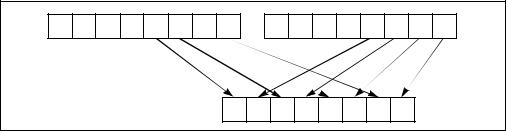
INSTRUCTION SET REFERENCE, N-Z
PUNPCKLBW/PUNPCKLWD/PUNPCKLDQ/PUNPCKLQDQ—
Unpack Low Data
|
|
|
64-Bit |
Compat/ |
|
Opcode |
Instruction |
Mode |
Leg Mode |
Description |
|
0F 60 |
/r |
PUNPCKLBW mm, |
Valid |
Valid |
Interleave low-order bytes from |
|
|
mm/m32 |
|
|
mm and mm/m32 into mm. |
66 0F |
60 |
PUNPCKLBW xmm1, |
Valid |
Valid |
Interleave low-order bytes from |
/r |
|
xmm2/m128 |
|
|
xmm1 and xmm2/m128 into |
|
|
|
|
|
xmm1. |
0F 61 |
/r |
PUNPCKLWD mm, |
Valid |
Valid |
Interleave low-order words from |
|
|
mm/m32 |
|
|
mm and mm/m32 into mm. |
66 0F |
61 |
PUNPCKLWD xmm1, |
Valid |
Valid |
Interleave low-order words from |
/r |
|
xmm2/m128 |
|
|
xmm1 and xmm2/m128 into |
|
|
|
|
|
xmm1. |
0F 62 |
/r |
PUNPCKLDQ mm, |
Valid |
Valid |
Interleave low-order doublewords |
|
|
mm/m32 |
|
|
from mm and mm/m32 into mm. |
66 0F |
62 |
PUNPCKLDQ xmm1, |
Valid |
Valid |
Interleave low-order doublewords |
/r |
|
xmm2/m128 |
|
|
from xmm1 and xmm2/m128 into |
|
|
|
|
|
xmm1. |
66 0F |
6C |
PUNPCKLQDQ |
Valid |
Valid |
Interleave low-order quadword |
/r |
|
xmm1, xmm2/m128 |
|
|
from xmm1 and xmm2/m128 into |
|
|
|
|
|
xmm1 register. |
|
|
|
|
|
|
Description
Unpacks and interleaves the low-order data elements (bytes, words, doublewords, and quadwords) of the destination operand (first operand) and source operand (second operand) into the destination operand. (Figure 4-12 shows the unpack operation for bytes in 64-bit operands.). The high-order data elements are ignored.
SRC |
Y7 |
Y6 |
Y5 |
Y4 |
Y3 |
Y2 |
Y1 |
Y0 |
|
X7 |
X6 |
X5 |
X4 |
X3 |
X2 |
X1 |
X0 |
DEST |
|
|
|
|
|
|
|
DEST |
Y3 |
X3 |
Y2 |
X2 |
Y1 |
X1 |
Y0 |
X0 |
|
|
|
Figure 4-12. PUNPCKLBW Instruction Operation Using 64-bit Operands
Vol. 2B 4-207
INSTRUCTION SET REFERENCE, N-Z
The source operand can be an MMX technology register or a 32-bit memory location, or it can be an XMM register or a 128-bit memory location. The destination operand can be an MMX technology register or an XMM register. When the source data comes from a 128-bit memory operand, an implementation may fetch only the appropriate 64 bits; however, alignment to a 16-byte boundary and normal segment checking will still be enforced.
The PUNPCKLBW instruction interleaves the low-order bytes of the source and destination operands, the PUNPCKLWD instruction interleaves the low-order words of the source and destination operands, the PUNPCKLDQ instruction interleaves the loworder doubleword (or doublewords) of the source and destination operands, and the PUNPCKLQDQ instruction interleaves the low-order quadwords of the source and destination operands.
These instructions can be used to convert bytes to words, words to doublewords, doublewords to quadwords, and quadwords to double quadwords, respectively, by placing all 0s in the source operand. Here, if the source operand contains all 0s, the result (stored in the destination operand) contains zero extensions of the high-order data elements from the original value in the destination operand. For example, with the PUNPCKLBW instruction the high-order bytes are zero extended (that is, unpacked into unsigned word integers), and with the PUNPCKLWD instruction, the high-order words are zero extended (unpacked into unsigned doubleword integers).
In 64-bit mode, using a REX prefix in the form of REX.R permits this instruction to access additional registers (XMM8-XMM15).
Operation
PUNPCKLBW instruction with 64-bit operands:
DEST[63:56] ← SRC[31:24];
DEST[55:48] ← DEST[31:24];
DEST[47:40] ← SRC[23:16];
DEST[39:32] ← DEST[23:16];
DEST[31:24] ← SRC[15:8];
DEST[23:16] ← DEST[15:8];
DEST[15:8] ← SRC[7:0];
DEST[7:0] ← DEST[7:0];
PUNPCKLWD instruction with 64-bit operands:
DEST[63:48] ← SRC[31:16];
DEST[47:32] ← DEST[31:16];
DEST[31:16] ← SRC[15:0];
DEST[15:0] ← DEST[15:0];
PUNPCKLDQ instruction with 64-bit operands:
DEST[63:32] ← SRC[31:0];
DEST[31:0] ← DEST[31:0];
4-208 Vol. 2B
INSTRUCTION SET REFERENCE, N-Z
PUNPCKLBW instruction with 128-bit operands:
DEST[7:0] ← DEST[7:0];
DEST[15:8] ← SRC[7:0];
DEST[23:16] ← DEST[15:8];
DEST[31:24] ← SRC[15:8];
DEST[39:32] ← DEST[23:16];
DEST[47:40] ← SRC[23:16];
DEST[55:48] ← DEST[31:24];
DEST[63:56] ← SRC[31:24];
DEST[71:64] ← DEST[39:32];
DEST[79:72] ← SRC[39:32];
DEST[87:80] ← DEST[47:40];
DEST[95:88] ← SRC[47:40];
DEST[103:96] ← DEST[55:48];
DEST[111:104] ← SRC[55:48];
DEST[119:112] ← DEST[63:56];
DEST[127:120] ← SRC[63:56];
PUNPCKLWD instruction with 128-bit operands:
DEST[15:0] ← DEST[15:0];
DEST[31:16] ← SRC[15:0];
DEST[47:32] ← DEST[31:16];
DEST[63:48] ← SRC[31:16];
DEST[79:64] ← DEST[47:32];
DEST[95:80] ← SRC[47:32];
DEST[111:96] ← DEST[63:48];
DEST[127:112] ← SRC[63:48];
PUNPCKLDQ instruction with 128-bit operands:
DEST[31:0] ← DEST[31:0];
DEST[63:32] ← SRC[31:0];
DEST[95:64] ← DEST[63:32];
DEST[127:96] ← SRC[63:32];
PUNPCKLQDQ
DEST[63:0] ← DEST[63:0];
DEST[127:64] ← SRC[63:0];
Intel C/C++ Compiler Intrinsic Equivalents
PUNPCKLBW |
__m64 |
_mm_unpacklo_pi8 (__m64 m1, __m64 m2) |
PUNPCKLBW |
__m128i _mm_unpacklo_epi8 (__m128i m1, __m128i m2) |
|
PUNPCKLWD |
__m64 |
_mm_unpacklo_pi16 (__m64 m1, __m64 m2) |
PUNPCKLWD |
__m128i _mm_unpacklo_epi16 (__m128i m1, __m128i m2) |
|
Vol. 2B 4-209
INSTRUCTION SET REFERENCE, N-Z
PUNPCKLDQ |
__m64 _mm_unpacklo_pi32 (__m64 m1, __m64 m2) |
PUNPCKLDQ |
__m128i _mm_unpacklo_epi32 (__m128i m1, __m128i m2) |
PUNPCKLQDQ |
__m128i _mm_unpacklo_epi64 (__m128i m1, __m128i m2) |
Flags Affected
None.
Numeric Exceptions
None.
Protected Mode Exceptions
#GP(0) |
If a memory operand effective address is outside the CS, DS, |
|
ES, FS, or GS segment limit. |
|
(128-bit operations only) If a memory operand is not aligned on |
|
a 16-byte boundary, regardless of segment. |
#SS(0) |
If a memory operand effective address is outside the SS |
|
segment limit. |
#UD |
If CR0.EM[bit 2] = 1. |
|
(128-bit operations only) If CR4.OSFXSR[bit 9] = 0. |
|
If CPUID.01H:EDX.SSE2[bit 26] = 0. |
#NM |
If CR0.TS[bit 3] = 1. |
#MF |
(64-bit operations only) If there is a pending x87 FPU exception. |
#PF(fault-code) |
If a page fault occurs. |
#AC(0) |
(64-bit operations only) If alignment checking is enabled and an |
|
unaligned memory reference is made while the current privilege |
|
level is 3. |
Real-Address Mode Exceptions
#GP(0) |
If any part of the operand lies outside of the effective address |
|
space from 0 to 0FFFFH. |
|
(128-bit operations only) If a memory operand is not aligned on |
|
a 16-byte boundary, regardless of segment. |
#UD |
If CR0.EM[bit 2] = 1. |
|
(128-bit operations only) If CR4.OSFXSR[bit 9] = 0. |
|
If CPUID.01H:EDX.SSE2[bit 26] = 0. |
#NM |
If CR0.TS[bit 3] = 1. |
#MF |
(64-bit operations only) If there is a pending x87 FPU exception. |
4-210 Vol. 2B
INSTRUCTION SET REFERENCE, N-Z
Virtual-8086 Mode Exceptions
Same exceptions as in Real Address Mode
#PF(fault-code) |
For a page fault. |
#AC(0) |
(64-bit operations only) If alignment checking is enabled and an |
|
unaligned memory reference is made. |
Compatibility Mode Exceptions
Same exceptions as in Protected Mode.
64-Bit Mode Exceptions
#SS(0) |
If a memory address referencing the SS segment is in a non- |
|
canonical form. |
#GP(0) |
If the memory address is in a non-canonical form. |
|
(128-bit version only) If memory operand is not aligned on a |
|
16-byte boundary, regardless of segment. |
#UD |
If CR0.EM[bit 2] = 1. |
#NM |
If CR0.TS[bit 3] = 1. |
#MF |
(64-bit operations only) If there is a pending x87 FPU exception. |
#PF(fault-code) |
If a page fault occurs. |
#AC(0) |
(64-bit operations only) If alignment checking is enabled and an |
|
unaligned memory reference is made while the current privilege |
|
level is 3. |
Vol. 2B 4-211

INSTRUCTION SET REFERENCE, N-Z
PUSH—Push Word, Doubleword or Quadword Onto the Stack
|
|
64-Bit |
Compat/ |
|
Opcode* |
Instruction |
Mode |
Leg Mode |
Description |
FF /6 |
PUSH r/m16 |
Valid |
Valid |
Push r/m16. |
FF /6 |
PUSH r/m32 |
N.E. |
Valid |
Push r/m32. |
FF /6 |
PUSH r/m64 |
Valid |
N.E. |
Push r/m64. Default operand size |
|
|
|
|
64-bits. |
50+rw |
PUSH r16 |
Valid |
Valid |
Push r16. |
50+rd |
PUSH r32 |
N.E. |
Valid |
Push r32. |
50+rd |
PUSH r64 |
Valid |
N.E. |
Push r64. Default operand size |
|
|
|
|
64-bits. |
6A |
PUSH imm8 |
Valid |
Valid |
Push sign-extended imm8. Stack |
|
|
|
|
pointer is incremented by the size |
|
|
|
|
of stack pointer. |
68 |
PUSH imm16 |
Valid |
Valid |
Push sign-extended imm16. Stack |
|
|
|
|
pointer is incremented by the size |
|
|
|
|
of stack pointer. |
68 |
PUSH imm32 |
Valid |
Valid |
Push sign-extended imm32. Stack |
|
|
|
|
pointer is incremented by the size |
|
|
|
|
of stack pointer. |
0E |
PUSH CS |
Invalid |
Valid |
Push CS. |
16 |
PUSH SS |
Invalid |
Valid |
Push SS. |
1E |
PUSH DS |
Invalid |
Valid |
Push DS. |
06 |
PUSH ES |
Invalid |
Valid |
Push ES. |
0F A0 |
PUSH FS |
Valid |
Valid |
Push FS and decrement stack |
|
|
|
|
pointer by 16 bits. |
0F A0 |
PUSH FS |
N.E. |
Valid |
Push FS and decrement stack |
|
|
|
|
pointer by 32 bits. |
0F A0 |
PUSH FS |
Valid |
N.E. |
Push FS. Default operand size |
|
|
|
|
64-bits. (66H override causes 16- |
|
|
|
|
bit operation). |
0F A8 |
PUSH GS |
Valid |
Valid |
Push GS and decrement stack |
|
|
|
|
pointer by 16 bits. |
0F A8 |
PUSH GS |
N.E. |
Valid |
Push GS and decrement stack |
|
|
|
|
pointer by 32 bits. |
0F A8 |
PUSH GS |
Valid |
N.E. |
Push GS, default operand size |
|
|
|
|
64-bits. (66H override causes 16- |
|
|
|
|
bit operation). |
NOTES:
* See IA-32 Architecture Compatibility section below.
4-212 Vol. 2B
INSTRUCTION SET REFERENCE, N-Z
Description
Decrements the stack pointer and then stores the source operand on the top of the stack. The address-size attribute of the stack segment determines the stack pointer size (16, 32 or 64 bits). The operand-size attribute of the current code segment determines the amount the stack pointer is decremented (2, 4 or 8 bytes).
In non-64-bit modes: if the address-size and operand-size attributes are 32, the 32-bit ESP register (stack pointer) is decremented by 4. If both attributes are 16, the 16-bit SP register (stack pointer) is decremented by 2.
If the source operand is an immediate and its size is less than the address size of the stack, a sign-extended value is pushed on the stack. If the source operand is the FS or GS and its size is less than the address size of the stack, the zero-extended value is pushed on the stack.
The B flag in the stack segment’s segment descriptor determines the stack’s addresssize attribute. The D flag in the current code segment’s segment descriptor (with prefixes), determines the operand-size attribute and the address-size attribute of the source operand. Pushing a 16-bit operand when the stack address-size attribute is 32 can result in a misaligned stack pointer (a stack pointer that is not be aligned on a doubleword boundary).
The PUSH ESP instruction pushes the value of the ESP register as it existed before the instruction was executed. Thus if a PUSH instruction uses a memory operand in which the ESP register is used for computing the operand address, the address of the operand is computed before the ESP register is decremented.
In the real-address mode, if the ESP or SP register is 1 when the PUSH instruction is executed, an #SS exception is generated but not delivered (the stack error reported prevents #SS delivery). Next, the processor generates a #DF exception and enters a shutdown state as described in the #DF discussion in Chapter 5 of the Intel® 64 and IA-32 Architectures Software Developer’s Manual, Volume 3A.
In 64-bit mode, the instruction’s default operation size is 64 bits. In a push, the 64-bit RSP register (stack pointer) is decremented by 8. A 66H override causes 16-bit operation. Note that pushing a 16-bit operand can result in the stack pointer misaligned to 8-byte boundary.
IA-32 Architecture Compatibility
For IA-32 processors from the Intel 286 on, the PUSH ESP instruction pushes the value of the ESP register as it existed before the instruction was executed. (This is also true for Intel 64 architecture, real-address and virtual-8086 modes of IA-32 architecture.) For the Intel® 8086 processor, the PUSH SP instruction pushes the new value of the SP register (that is the value after it has been decremented by 2).
Vol. 2B 4-213
INSTRUCTION SET REFERENCE, N-Z
Operation
IF StackAddrSize = 64 THEN
IF OperandSize = 64 THEN
RSP ← (RSP − 8); IF (SRC is FS or GS)
THEN
TEMP = ZeroExtend64(SRC); ELSE IF (SRC is IMMEDIATE)
TEMP = SignExtend64(SRC); FI; ELSE
TEMP = SRC;
FI
RSP ← TEMP; (* Push quadword *) ELSE (* OperandSize = 16; 66H used *)
RSP ← (RSP − 2);
RSP ← SRC; (* Push word *)
FI;
ELSE IF StackAddrSize = 32 THEN
IF OperandSize = 32 THEN
ESP ← (ESP − 4); IF (SRC is FS or GS)
THEN
TEMP = ZeroExtend32(SRC); ELSE IF (SRC is IMMEDIATE)
TEMP = SignExtend32(SRC); FI; ELSE
TEMP = SRC;
FI;
SS:ESP ← TEMP; (* Push doubleword *) ELSE (* OperandSize = 16*)
ESP ← (ESP − 2);
SS:ESP ← SRC; (* Push word *)
FI;
ELSE StackAddrSize = 16 IF OperandSize = 16
THEN
SP ← (SP − 2);
SS:SP ← SRC; (* Push word *) ELSE (* OperandSize = 32 *)
4-214 Vol. 2B
INSTRUCTION SET REFERENCE, N-Z
SP ← (SP − 4);
SS:SP ← SRC; (* Push doubleword *)
FI;
FI;
FI;
Flags Affected
None.
Protected Mode Exceptions
#GP(0) |
If a memory operand effective address is outside the CS, DS, |
|
ES, FS, or GS segment limit. |
|
If the DS, ES, FS, or GS register is used to access memory and it |
|
contains a NULL segment selector. |
#SS(0) |
If a memory operand effective address is outside the SS |
|
segment limit. |
#PF(fault-code) |
If a page fault occurs. |
#AC(0) |
If alignment checking is enabled and an unaligned memory |
|
reference is made while the current privilege level is 3. |
Real-Address Mode Exceptions
#GP |
If a memory operand effective address is outside the CS, DS, |
|
ES, FS, or GS segment limit. |
#SS |
If a memory operand effective address is outside the SS |
|
segment limit. |
|
If the new value of the SP or ESP register is outside the stack |
|
segment limit. |
Virtual-8086 Mode Exceptions
#GP(0) |
If a memory operand effective address is outside the CS, DS, |
|
ES, FS, or GS segment limit. |
#SS(0) |
If a memory operand effective address is outside the SS |
|
segment limit. |
#PF(fault-code) |
If a page fault occurs. |
#AC(0) |
If alignment checking is enabled and an unaligned memory |
|
reference is made. |
Compatibility Mode Exceptions
Same exceptions as in Protected Mode.
Vol. 2B 4-215
INSTRUCTION SET REFERENCE, N-Z
64-Bit Mode Exceptions
#GP(0) |
If the memory address is in a non-canonical form. |
#SS(U) |
If the stack address is in a non-canonical form. |
#PF(fault-code) |
If a page fault occurs. |
#AC(0) |
If alignment checking is enabled and an unaligned memory |
|
reference is made while the current privilege level is 3. |
4-216 Vol. 2B
INSTRUCTION SET REFERENCE, N-Z
PUSHA/PUSHAD—Push All General-Purpose Registers
|
|
64-Bit |
Compat/ |
|
Opcode |
Instruction |
Mode |
Leg Mode |
Description |
60 |
PUSHA |
Invalid |
Valid |
Push AX, CX, DX, BX, original SP, BP, SI, |
|
|
|
|
and DI. |
60 |
PUSHAD |
Invalid |
Valid |
Push EAX, ECX, EDX, EBX, original ESP, |
|
|
|
|
EBP, ESI, and EDI. |
|
|
|
|
|
Description
Pushes the contents of the general-purpose registers onto the stack. The registers are stored on the stack in the following order: EAX, ECX, EDX, EBX, ESP (original value), EBP, ESI, and EDI (if the current operand-size attribute is 32) and AX, CX, DX, BX, SP (original value), BP, SI, and DI (if the operand-size attribute is 16). These instructions perform the reverse operation of the POPA/POPAD instructions. The value pushed for the ESP or SP register is its value before prior to pushing the first register (see the “Operation” section below).
The PUSHA (push all) and PUSHAD (push all double) mnemonics reference the same opcode. The PUSHA instruction is intended for use when the operand-size attribute is 16 and the PUSHAD instruction for when the operand-size attribute is 32. Some assemblers may force the operand size to 16 when PUSHA is used and to 32 when PUSHAD is used. Others may treat these mnemonics as synonyms (PUSHA/PUSHAD) and use the current setting of the operand-size attribute to determine the size of values to be pushed from the stack, regardless of the mnemonic used.
In the real-address mode, if the ESP or SP register is 1, 3, or 5 when PUSHA/PUSHAD executes: an #SS exception is generated but not delivered (the stack error reported prevents #SS delivery). Next, the processor generates a #DF exception and enters a shutdown state as described in the #DF discussion in Chapter 5 of the Intel® 64 and IA-32 Architectures Software Developer’s Manual, Volume 3A.
This instruction executes as described in compatibility mode and legacy mode. It is not valid in 64-bit mode.
Operation
IF 64-bit Mode
THEN #UD
FI;
IF OperandSize = 32 (* PUSHAD instruction *)
THEN
Temp ← (ESP);
Push(EAX);
Vol. 2B 4-217
INSTRUCTION SET REFERENCE, N-Z
Push(ECX);
Push(EDX);
Push(EBX);
Push(Temp);
Push(EBP);
Push(ESI);
Push(EDI);
ELSE (* OperandSize = 16, PUSHA instruction *)
Temp ← (SP);
Push(AX);
Push(CX);
Push(DX);
Push(BX);
Push(Temp);
Push(BP);
Push(SI);
Push(DI);
FI;
Flags Affected
None.
Protected Mode Exceptions
#SS(0) |
If the starting or ending stack address is outside the stack |
|
segment limit. |
#PF(fault-code) |
If a page fault occurs. |
#AC(0) |
If an unaligned memory reference is made while the current |
|
privilege level is 3 and alignment checking is enabled. |
Real-Address Mode Exceptions
#GP If the ESP or SP register contains 7, 9, 11, 13, or 15.
Virtual-8086 Mode Exceptions
#GP(0) |
If the ESP or SP register contains 7, 9, 11, 13, or 15. |
#PF(fault-code) |
If a page fault occurs. |
#AC(0) |
If an unaligned memory reference is made while alignment |
|
checking is enabled. |
4-218 Vol. 2B
INSTRUCTION SET REFERENCE, N-Z
Compatibility Mode Exceptions
Same exceptions as in Protected Mode.
64-Bit Mode Exceptions
#UD |
If in 64-bit mode. |
Vol. 2B 4-219
INSTRUCTION SET REFERENCE, N-Z
PUSHF/PUSHFD—Push EFLAGS Register onto the Stack
|
|
64-Bit |
Compat/ |
|
Opcode |
Instruction |
Mode |
Leg Mode |
Description |
9C |
PUSHF |
Valid |
Valid |
Push lower 16 bits of EFLAGS. |
9C |
PUSHFD |
N.E. |
Valid |
Push EFLAGS. |
9C |
PUSHFQ |
Valid |
N.E. |
Push RFLAGS. |
|
|
|
|
|
Description
Decrements the stack pointer by 4 (if the current operand-size attribute is 32) and pushes the entire contents of the EFLAGS register onto the stack, or decrements the stack pointer by 2 (if the operand-size attribute is 16) and pushes the lower 16 bits of the EFLAGS register (that is, the FLAGS register) onto the stack. These instructions reverse the operation of the POPF/POPFD instructions.
When copying the entire EFLAGS register to the stack, the VM and RF flags (bits 16 and 17) are not copied; instead, the values for these flags are cleared in the EFLAGS image stored on the stack. See Chapter 3 of the Intel® 64 and IA-32 Architectures Software Developer’s Manual, Volume 1, for more information about the EFLAGS register.
The PUSHF (push flags) and PUSHFD (push flags double) mnemonics reference the same opcode. The PUSHF instruction is intended for use when the operand-size attribute is 16 and the PUSHFD instruction for when the operand-size attribute is 32. Some assemblers may force the operand size to 16 when PUSHF is used and to 32 when PUSHFD is used. Others may treat these mnemonics as synonyms (PUSHF/PUSHFD) and use the current setting of the operand-size attribute to determine the size of values to be pushed from the stack, regardless of the mnemonic used.
In 64-bit mode, the instruction’s default operation is to decrement the stack pointer (RSP) by 8 and pushs RFLAGS on the stack. 16-bit operation is supported using the operand size override prefix 66H. 32-bit operand size cannot be encoded in this mode. When copying RFLAGS to the stack, the VM and RF flags (bits 16 and 17) are not copied; instead, values for these flags are cleared in the RFLAGS image stored on the stack.
When in virtual-8086 mode and the I/O privilege level (IOPL) is less than 3, the PUSHF/PUSHFD instruction causes a general protection exception (#GP).
In the real-address mode, if the ESP or SP register is 1 when PUSHF/PUSHFD instruction executes: an #SS exception is generated but not delivered (the stack error reported prevents #SS delivery). Next, the processor generates a #DF exception and enters a shutdown state as described in the #DF discussion in Chapter 5 of the Intel® 64 and IA-32 Architectures Software Developer’s Manual, Volume 3A.
4-220 Vol. 2B
INSTRUCTION SET REFERENCE, N-Z
Operation
IF (PE = 0) or (PE = 1 and ((VM = 0) or (VM = 1 and IOPL = 3)))
(* Real-Address Mode, Protected mode, or Virtual-8086 mode with IOPL equal to 3 *) THEN
IF OperandSize = 32 THEN
push (EFLAGS AND 00FCFFFFH);
(* VM and RF EFLAG bits are cleared in image stored on the stack *) ELSE
push (EFLAGS); (* Lower 16 bits only *)
FI;
ELSE IF 64-bit MODE (* In 64-bit Mode *) IF OperandSize = 64
THEN
push (RFLAGS AND 00000000_00FCFFFFH);
(* VM and RF RFLAG bits are cleared in image stored on the stack; *) ELSE
push (EFLAGS); (* Lower 16 bits only *)
FI;
ELSE (* In Virtual-8086 Mode with IOPL less than 3 *) #GP(0); (* Trap to virtual-8086 monitor *)
FI;
Flags Affected
None.
Protected Mode Exceptions
#SS(0) |
If the new value of the ESP register is outside the stack segment |
|
boundary. |
#PF(fault-code) |
If a page fault occurs. |
#AC(0) |
If an unaligned memory reference is made while the current |
|
privilege level is 3 and alignment checking is enabled. |
Real-Address Mode Exceptions
None.
Virtual-8086 Mode Exceptions
#GP(0) |
If the I/O privilege level is less than 3. |
#PF(fault-code) |
If a page fault occurs. |
Vol. 2B 4-221
INSTRUCTION SET REFERENCE, N-Z
#AC(0) |
If an unaligned memory reference is made while alignment |
|
checking is enabled. |
Compatibility Mode Exceptions
Same exceptions as in Protected Mode.
64-Bit Mode Exceptions
#GP(0) |
If the memory address is in a non-canonical form. |
#SS(U) |
If the stack address is in a non-canonical form. |
#PF(fault-code) |
If a page fault occurs. |
#AC(0) |
If an unaligned memory reference is made while the current |
|
privilege level is 3 and alignment checking is enabled. |
4-222 Vol. 2B
INSTRUCTION SET REFERENCE, N-Z
PXOR—Logical Exclusive OR
|
|
64-Bit |
Compat/ |
|
Opcode |
Instruction |
Mode |
Leg Mode |
Description |
0F EF /r |
PXOR mm, mm/m64 |
Valid |
Valid |
Bitwise XOR of |
|
|
|
|
mm/m64 and mm. |
66 0F EF |
PXOR xmm1, xmm2/m128 |
Valid |
Valid |
Bitwise XOR of |
/r |
|
|
|
xmm2/m128 and |
|
|
|
|
xmm1. |
|
|
|
|
|
Description
Performs a bitwise logical exclusive-OR (XOR) operation on the source operand (second operand) and the destination operand (first operand) and stores the result in the destination operand. The source operand can be an MMX technology register or a 64-bit memory location or it can be an XMM register or a 128-bit memory location. The destination operand can be an MMX technology register or an XMM register. Each bit of the result is 1 if the corresponding bits of the two operands are different; each bit is 0 if the corresponding bits of the operands are the same.
In 64-bit mode, using a REX prefix in the form of REX.R permits this instruction to access additional registers (XMM8-XMM15).
Operation
DEST ← DEST XOR SRC;
Intel C/C++ Compiler Intrinsic Equivalent
PXOR |
__m64 _mm_xor_si64 (__m64 m1, __m64 m2) |
PXOR |
__m128i _mm_xor_si128 ( __m128i a, __m128i b) |
Flags Affected
None.
Numeric Exceptions
None.
Protected Mode Exceptions
#GP(0) |
If a memory operand effective address is outside the CS, DS, |
|
ES, FS, or GS segment limit. |
|
(128-bit operations only) If a memory operand is not aligned on |
|
a 16-byte boundary, regardless of segment. |
Vol. 2B 4-223
INSTRUCTION SET REFERENCE, N-Z
#SS(0) |
If a memory operand effective address is outside the SS |
|
segment limit. |
#UD |
If CR0.EM[bit 2] = 1. |
|
(128-bit operations only) If CR4.OSFXSR[bit 9] = 0. |
|
(128-bit operations only) If CPUID.01H:EDX.SSE2[bit 26] = 0. |
#NM |
If CR0.TS[bit 3] = 1. |
#MF |
(64-bit operations only) If there is a pending x87 FPU exception. |
#PF(fault-code) |
If a page fault occurs. |
#AC(0) |
(64-bit operations only) If alignment checking is enabled and an |
|
unaligned memory reference is made while the current privilege |
|
level is 3. |
Real-Address Mode Exceptions
#GP(0) |
(128-bit operations only) If a memory operand is not aligned on |
|
a 16-byte boundary, regardless of segment. |
|
If any part of the operand lies outside of the effective address |
|
space from 0 to FFFFH. |
#UD |
If CR0.EM[bit 2] = 1. |
|
(128-bit operations only) If CR4.OSFXSR[bit 9] = 0. |
|
(128-bit operations only) If CPUID.01H:EDX.SSE2[bit 26] = 0. |
#NM |
If CR0.TS[bit 3] = 1. |
#MF |
(64-bit operations only) If there is a pending x87 FPU exception. |
Virtual-8086 Mode Exceptions
Same exceptions as in Real Address Mode
#PF(fault-code) |
For a page fault. |
#AC(0) |
(64-bit operations only) If alignment checking is enabled and an |
|
unaligned memory reference is made. |
Compatibility Mode Exceptions
Same exceptions as in Protected Mode.
64-Bit Mode Exceptions
#SS(0) |
If a memory address referencing the SS segment is in a non- |
|
canonical form. |
#GP(0) |
If the memory address is in a non-canonical form. |
|
(128-bit operations only) If memory operand is not aligned on a |
|
16-byte boundary, regardless of segment. |
UD |
If CR0.EM[bit 2] = 1. |
4-224 Vol. 2B
|
INSTRUCTION SET REFERENCE, N-Z |
|
(128-bit operations only) If CR4.OSFXSR[bit 9] = 0. |
|
(128-bit operations only) If CPUID.01H:EDX.SSE2[bit 26] = 0. |
#NM |
If CR0.TS[bit 3] = 1. |
#MF |
(64-bit operations only) If there is a pending x87 FPU exception. |
#PF(fault-code) |
If a page fault occurs. |
#AC(0) |
(64-bit operations only) If alignment checking is enabled and an |
|
unaligned memory reference is made while the current privilege |
|
level is 3. |
Vol. 2B 4-225
INSTRUCTION SET REFERENCE, N-Z
RCL/RCR/ROL/ROR-—Rotate
|
|
|
Compat/ |
|
|
|
64-Bit |
Leg |
|
Opcode** |
Instruction |
Mode |
Mode |
Description |
D0 /2 |
RCL r/m8, 1 |
Valid |
Valid |
Rotate 9 bits (CF, r/m8) left once. |
REX + D0 /2 |
RCL r/m8*, 1 |
Valid |
N.E. |
Rotate 9 bits (CF, r/m8) left once. |
D2 /2 |
RCL r/m8, CL |
Valid |
Valid |
Rotate 9 bits (CF, r/m8) left CL |
|
|
|
|
times. |
REX + D2 /2 |
RCL r/m8*, CL |
Valid |
N.E. |
Rotate 9 bits (CF, r/m8) left CL |
|
|
|
|
times. |
C0 /2 ib |
RCL r/m8, |
Valid |
Valid |
Rotate 9 bits (CF, r/m8) left imm8 |
|
imm8 |
|
|
times. |
REX + C0 /2 ib |
RCL r/m8*, |
Valid |
N.E. |
Rotate 9 bits (CF, r/m8) left imm8 |
|
imm8 |
|
|
times. |
D1 /2 |
RCL r/m16, 1 |
Valid |
Valid |
Rotate 17 bits (CF, r/m16) left |
|
|
|
|
once. |
D3 /2 |
RCL r/m16, CL |
Valid |
Valid |
Rotate 17 bits (CF, r/m16) left CL |
|
|
|
|
times. |
C1 /2 ib |
RCL r/m16, |
Valid |
Valid |
Rotate 17 bits (CF, r/m16) left |
|
imm8 |
|
|
imm8 times. |
D1 /2 |
RCL r/m32, 1 |
Valid |
Valid |
Rotate 33 bits (CF, r/m32) left |
|
|
|
|
once. |
REX.W + D1 /2 |
RCL r/m64, 1 |
Valid |
N.E. |
Rotate 65 bits (CF, r/m64) left |
|
|
|
|
once. Uses a 6 bit count. |
D3 /2 |
RCL r/m32, CL |
Valid |
Valid |
Rotate 33 bits (CF, r/m32) left CL |
|
|
|
|
times. |
REX.W + D3 /2 |
RCL r/m64, CL |
Valid |
N.E. |
Rotate 65 bits (CF, r/m64) left CL |
|
|
|
|
times. Uses a 6 bit count. |
C1 /2 ib |
RCL r/m32, |
Valid |
Valid |
Rotate 33 bits (CF, r/m32) left |
|
imm8 |
|
|
imm8 times. |
REX.W + C1 /2 |
RCL r/m64, |
Valid |
N.E. |
Rotate 65 bits (CF, r/m64) left |
ib |
imm8 |
|
|
imm8 times. Uses a 6 bit count. |
D0 /3 |
RCR r/m8, 1 |
Valid |
Valid |
Rotate 9 bits (CF, r/m8) right once. |
REX + D0 /3 |
RCR r/m8*, 1 |
Valid |
N.E. |
Rotate 9 bits (CF, r/m8) right once. |
D2 /3 |
RCR r/m8, CL |
Valid |
Valid |
Rotate 9 bits (CF, r/m8) right CL |
|
|
|
|
times. |
REX + D2 /3 |
RCR r/m8*, CL |
Valid |
N.E. |
Rotate 9 bits (CF, r/m8) right CL |
|
|
|
|
times. |
|
|
|
|
|
4-226 Vol. 2B
|
|
|
|
INSTRUCTION SET REFERENCE, N-Z |
|
|
|
|
|
|
|
|
Compat/ |
|
|
|
64-Bit |
Leg |
|
Opcode** |
Instruction |
Mode |
Mode |
Description |
C0 /3 ib |
RCR r/m8, |
Valid |
Valid |
Rotate 9 bits (CF, r/m8) right |
|
imm8 |
|
|
imm8 times. |
REX + C0 /3 ib |
RCR r/m8*, |
Valid |
N.E. |
Rotate 9 bits (CF, r/m8) right |
|
imm8 |
|
|
imm8 times. |
D1 /3 |
RCR r/m16, 1 |
Valid |
Valid |
Rotate 17 bits (CF, r/m16) right |
|
|
|
|
once. |
D3 /3 |
RCR r/m16, CL |
Valid |
Valid |
Rotate 17 bits (CF, r/m16) right CL |
|
|
|
|
times. |
C1 /3 ib |
RCR r/m16, |
Valid |
Valid |
Rotate 17 bits (CF, r/m16) right |
|
imm8 |
|
|
imm8 times. |
D1 /3 |
RCR r/m32, 1 |
Valid |
Valid |
Rotate 33 bits (CF, r/m32) right |
|
|
|
|
once. Uses a 6 bit count. |
REX.W + D1 /3 |
RCR r/m64, 1 |
Valid |
N.E. |
Rotate 65 bits (CF, r/m64) right |
|
|
|
|
once. Uses a 6 bit count. |
D3 /3 |
RCR r/m32, CL |
Valid |
Valid |
Rotate 33 bits (CF, r/m32) right CL |
|
|
|
|
times. |
REX.W + D3 /3 |
RCR r/m64, CL |
Valid |
N.E. |
Rotate 65 bits (CF, r/m64) right CL |
|
|
|
|
times. Uses a 6 bit count. |
C1 /3 ib |
RCR r/m32, |
Valid |
Valid |
Rotate 33 bits (CF, r/m32) right |
|
imm8 |
|
|
imm8 times. |
REX.W + C1 /3 |
RCR r/m64, |
Valid |
N.E. |
Rotate 65 bits (CF, r/m64) right |
ib |
imm8 |
|
|
imm8 times. Uses a 6 bit count. |
D0 /0 |
ROL r/m8, 1 |
Valid |
Valid |
Rotate 8 bits r/m8 left once. |
REX + D0 /0 |
ROL r/m8*, 1 |
Valid |
N.E. |
Rotate 8 bits r/m8 left once |
D2 /0 |
ROL r/m8, CL |
Valid |
Valid |
Rotate 8 bits r/m8 left CL times. |
REX + D2 /0 |
ROL r/m8*, CL |
Valid |
N.E. |
Rotate 8 bits r/m8 left CL times. |
C0 /0 ib |
ROL r/m8, |
Valid |
Valid |
Rotate 8 bits r/m8 left imm8 |
|
imm8 |
|
|
times. |
REX + C0 /0 ib |
ROL r/m8*, |
Valid |
N.E. |
Rotate 8 bits r/m8 left imm8 |
|
imm8 |
|
|
times. |
D1 /0 |
ROL r/m16, 1 |
Valid |
Valid |
Rotate 16 bits r/m16 left once. |
D3 /0 |
ROL r/m16, CL |
Valid |
Valid |
Rotate 16 bits r/m16 left CL |
|
|
|
|
times. |
C1 /0 ib |
ROL r/m16, |
Valid |
Valid |
Rotate 16 bits r/m16 left imm8 |
|
imm8 |
|
|
times. |
D1 /0 |
ROL r/m32, 1 |
Valid |
Valid |
Rotate 32 bits r/m32 left once. |
REX.W + D1 /0 |
ROL r/m64, 1 |
Valid |
N.E. |
Rotate 64 bits r/m64 left once. |
|
|
|
|
Uses a 6 bit count. |
|
|
|
|
|
Vol. 2B 4-227

INSTRUCTION SET REFERENCE, N-Z
|
|
|
Compat/ |
|
|
|
64-Bit |
Leg |
|
Opcode** |
Instruction |
Mode |
Mode |
Description |
D3 /0 |
ROL r/m32, CL |
Valid |
Valid |
Rotate 32 bits r/m32 left CL |
|
|
|
|
times. |
REX.W + D3 /0 |
ROL r/m64, CL |
Valid |
N.E. |
Rotate 64 bits r/m64 left CL |
|
|
|
|
times. Uses a 6 bit count. |
C1 /0 ib |
ROL r/m32, |
Valid |
Valid |
Rotate 32 bits r/m32 left imm8 |
|
imm8 |
|
|
times. |
C1 /0 ib |
ROL r/m64, |
Valid |
N.E. |
Rotate 64 bits r/m64 left imm8 |
|
imm8 |
|
|
times. Uses a 6 bit count. |
D0 /1 |
ROR r/m8, 1 |
Valid |
Valid |
Rotate 8 bits r/m8 right once. |
REX + D0 /1 |
ROR r/m8*, 1 |
Valid |
N.E. |
Rotate 8 bits r/m8 right once. |
D2 /1 |
ROR r/m8, CL |
Valid |
Valid |
Rotate 8 bits r/m8 right CL times. |
REX + D2 /1 |
ROR r/m8*, CL |
Valid |
N.E. |
Rotate 8 bits r/m8 right CL times. |
C0 /1 ib |
ROR r/m8, |
Valid |
Valid |
Rotate 8 bits r/m16 right imm8 |
|
imm8 |
|
|
times. |
REX + C0 /1 ib |
ROR r/m8*, |
Valid |
N.E. |
Rotate 8 bits r/m16 right imm8 |
|
imm8 |
|
|
times. |
D1 /1 |
ROR r/m16, 1 |
Valid |
Valid |
Rotate 16 bits r/m16 right once. |
D3 /1 |
ROR r/m16, CL |
Valid |
Valid |
Rotate 16 bits r/m16 right CL |
|
|
|
|
times. |
C1 /1 ib |
ROR r/m16, |
Valid |
Valid |
Rotate 16 bits r/m16 right imm8 |
|
imm8 |
|
|
times. |
D1 /1 |
ROR r/m32, 1 |
Valid |
Valid |
Rotate 32 bits r/m32 right once. |
REX.W + D1 /1 |
ROR r/m64, 1 |
Valid |
N.E. |
Rotate 64 bits r/m64 right once. |
|
|
|
|
Uses a 6 bit count. |
D3 /1 |
ROR r/m32, CL |
Valid |
Valid |
Rotate 32 bits r/m32 right CL |
|
|
|
|
times. |
REX.W + D3 /1 |
ROR r/m64, CL |
Valid |
N.E. |
Rotate 64 bits r/m64 right CL |
|
|
|
|
times. Uses a 6 bit count. |
C1 /1 ib |
ROR r/m32, |
Valid |
Valid |
Rotate 32 bits r/m32 right imm8 |
|
imm8 |
|
|
times. |
REX.W + C1 /1 |
ROR r/m64, |
Valid |
N.E. |
Rotate 64 bits r/m64 right imm8 |
ib |
imm8 |
|
|
times. Uses a 6 bit count. |
NOTES:
*In 64-bit mode, r/m8 can not be encoded to access the following byte registers if a REX prefix is used: AH, BH, CH, DH.
**See IA-32 Architecture Compatibility section below.
4-228 Vol. 2B
INSTRUCTION SET REFERENCE, N-Z
Description
Shifts (rotates) the bits of the first operand (destination operand) the number of bit positions specified in the second operand (count operand) and stores the result in the destination operand. The destination operand can be a register or a memory location; the count operand is an unsigned integer that can be an immediate or a value in the CL register. In legacy and compatibility mode, the processor restricts the count to a number between 0 and 31 by masking all the bits in the count operand except the 5 least-significant bits.
The rotate left (ROL) and rotate through carry left (RCL) instructions shift all the bits toward more-significant bit positions, except for the most-significant bit, which is rotated to the least-significant bit location. The rotate right (ROR) and rotate through carry right (RCR) instructions shift all the bits toward less significant bit positions, except for the least-significant bit, which is rotated to the most-significant bit location.
The RCL and RCR instructions include the CF flag in the rotation. The RCL instruction shifts the CF flag into the least-significant bit and shifts the most-significant bit into the CF flag. The RCR instruction shifts the CF flag into the most-significant bit and shifts the least-significant bit into the CF flag. For the ROL and ROR instructions, the original value of the CF flag is not a part of the result, but the CF flag receives a copy of the bit that was shifted from one end to the other.
The OF flag is defined only for the 1-bit rotates; it is undefined in all other cases (except that a zero-bit rotate does nothing, that is affects no flags). For left rotates, the OF flag is set to the exclusive OR of the CF bit (after the rotate) and the mostsignificant bit of the result. For right rotates, the OF flag is set to the exclusive OR of the two most-significant bits of the result.
In 64-bit mode, using a REX prefix in the form of REX.R permits access to additional registers (R8-R15). Use of REX.W promotes the first operand to 64 bits and causes the count operand to become a 6-bit counter.
IA-32 Architecture Compatibility
The 8086 does not mask the rotation count. However, all other IA-32 processors (starting with the Intel 286 processor) do mask the rotation count to 5 bits, resulting in a maximum count of 31. This masking is done in all operating modes (including the virtual-8086 mode) to reduce the maximum execution time of the instructions.
Operation
(* RCL and RCR instructions *) SIZE ← OperandSize;
CASE (determine count) OF
SIZE ← 8: tempCOUNT ← (COUNT AND 1FH) MOD 9; SIZE ← 16: tempCOUNT ← (COUNT AND 1FH) MOD 17; SIZE ← 32: tempCOUNT ← COUNT AND 1FH;
Vol. 2B 4-229
INSTRUCTION SET REFERENCE, N-Z
SIZE ← 64: tempCOUNT ← COUNT AND 3FH;
ESAC;
(* RCL instruction operation *) WHILE (tempCOUNT ≠ 0)
DO
tempCF ← MSB(DEST); DEST ← (DEST 2) + CF; CF ← tempCF;
tempCOUNT ← tempCOUNT – 1;
OD;
ELIHW;
IF COUNT = 1
THEN OF ← MSB(DEST) XOR CF; ELSE OF is undefined;
FI;
(* RCR instruction operation *) IF COUNT = 1
THEN OF ← MSB(DEST) XOR CF; ELSE OF is undefined;
FI;
WHILE (tempCOUNT ≠ 0) DO
tempCF ← LSB(SRC);
DEST ← (DEST / 2) + (CF * 2SIZE); CF ← tempCF;
tempCOUNT ← tempCOUNT – 1;
OD;
(* ROL and ROR instructions *) SIZE ← OperandSize;
CASE (determine count) OF
SIZE ← 8: tempCOUNT ← (COUNT AND 1FH) MOD 8; (* Mask count before MOD *) SIZE ← 16: tempCOUNT ← (COUNT AND 1FH) MOD 16;
SIZE ← 32: tempCOUNT ← (COUNT AND 1FH) MOD 32; SIZE ← 64: tempCOUNT ← (COUNT AND 1FH) MOD 64;
ESAC;
(* ROL instruction operation *)
IF (tempCOUNT > 0) (* Prevents updates to CF *) WHILE (tempCOUNT ≠0)
DO
4-230 Vol. 2B
INSTRUCTION SET REFERENCE, N-Z
tempCF ← MSB(DEST);
DEST ← (DEST 2) + tempCF; tempCOUNT ← tempCOUNT – 1;
OD;
ELIHW;
CF ← LSB(DEST); IF COUNT = 1
THEN OF ← MSB(DEST) XOR CF; ELSE OF is undefined;
FI;
FI;
(* ROR instruction operation *)
IF tempCOUNT > 0) (* Prevent updates to CF *) WHILE (tempCOUNT ≠0)
DO
tempCF ← LSB(SRC);
DEST ← (DEST / 2) + (tempCF 2SIZE); tempCOUNT ← tempCOUNT – 1;
OD;
ELIHW;
CF ← MSB(DEST); IF COUNT = 1
THEN OF ← MSB(DEST) XOR MSB − 1(DEST); ELSE OF is undefined;
FI;
FI;
Flags Affected
The CF flag contains the value of the bit shifted into it. The OF flag is affected only for single-bit rotates (see “Description” above); it is undefined for multi-bit rotates. The SF, ZF, AF, and PF flags are not affected.
Protected Mode Exceptions
#GP(0) |
If the source operand is located in a non-writable segment. |
|
If a memory operand effective address is outside the CS, DS, |
|
ES, FS, or GS segment limit. |
|
If the DS, ES, FS, or GS register contains a NULL segment |
|
selector. |
#SS(0) |
If a memory operand effective address is outside the SS |
|
segment limit. |
#PF(fault-code) |
If a page fault occurs. |
Vol. 2B 4-231
INSTRUCTION SET REFERENCE, N-Z
#AC(0) |
If alignment checking is enabled and an unaligned memory |
|
reference is made while the current privilege level is 3. |
Real-Address Mode Exceptions
#GP |
If a memory operand effective address is outside the CS, DS, |
|
ES, FS, or GS segment limit. |
#SS |
If a memory operand effective address is outside the SS |
|
segment limit. |
Virtual-8086 Mode Exceptions
#GP(0) |
If a memory operand effective address is outside the CS, DS, |
|
ES, FS, or GS segment limit. |
#SS(0) |
If a memory operand effective address is outside the SS |
|
segment limit. |
#PF(fault-code) |
If a page fault occurs. |
#AC(0) |
If alignment checking is enabled and an unaligned memory |
|
reference is made. |
Compatibility Mode Exceptions
Same exceptions as in Protected Mode.
64-Bit Mode Exceptions
#SS(0) |
If a memory address referencing the SS segment is in a non- |
|
canonical form. |
#GP(0) |
If the source operand is located in a nonwritable segment. |
|
If the memory address is in a non-canonical form. |
#PF(fault-code) |
If a page fault occurs. |
#AC(0) |
If alignment checking is enabled and an unaligned memory |
|
reference is made while the current privilege level is 3. |
4-232 Vol. 2B
INSTRUCTION SET REFERENCE, N-Z
RCPPS—Compute Reciprocals of Packed Single-Precision Floating-
Point Values
|
|
64-Bit |
Compat/ |
|
Opcode |
Instruction |
Mode |
Leg Mode |
Description |
0F 53 /r |
RCPPS xmm1, |
Valid |
Valid |
Computes the approximate reciprocals |
|
xmm2/m128 |
|
|
of the packed single-precision floating- |
|
|
|
|
point values in xmm2/m128 and |
|
|
|
|
stores the results in xmm1. |
|
|
|
|
|
Description
Performs a SIMD computation of the approximate reciprocals of the four packed single-precision floating-point values in the source operand (second operand) stores the packed single-precision floating-point results in the destination operand. The source operand can be an XMM register or a 128-bit memory location. The destination operand is an XMM register. See Figure 10-5 in the Intel® 64 and IA-32 Architectures Software Developer’s Manual, Volume 1, for an illustration of a SIMD singleprecision floating-point operation.
The relative error for this approximation is:
|Relative Error| ≤ 1.5 2−12
The RCPPS instruction is not affected by the rounding control bits in the MXCSR register. When a source value is a 0.0, an ∞ of the sign of the source value is returned. A denormal source value is treated as a 0.0 (of the same sign). Tiny results are always flushed to 0.0, with the sign of the operand. (Input values greater than or equal to |1.11111111110100000000000B 2125| are guaranteed to not produce tiny results; input values less than or equal to |1.00000000000110000000001B*2126| are guaranteed to produce tiny results, which are in turn flushed to 0.0; and input values in between this range may or may not produce tiny results, depending on the implementation.) When a source value is an SNaN or QNaN, the SNaN is converted to a QNaN or the source QNaN is returned.
In 64-bit mode, using a REX prefix in the form of REX.R permits this instruction to access additional registers (XMM8-XMM15).
Operation
DEST[31:0] ← APPROXIMATE(1.0/(SRC[31:0]));
DEST[63:32] ← APPROXIMATE(1.0/(SRC[63:32]));
DEST[95:64] ← APPROXIMATE(1.0/(SRC[95:64]));
DEST[127:96] ← APPROXIMATE(1.0/(SRC[127:96]));
Intel C/C++ Compiler Intrinsic Equivalent
RCCPS |
__m128 _mm_rcp_ps(__m128 a) |
Vol. 2B 4-233
INSTRUCTION SET REFERENCE, N-Z
SIMD Floating-Point Exceptions
None.
Protected Mode Exceptions
#GP(0) |
For an illegal memory operand effective address in the CS, DS, |
|
ES, FS or GS segments. |
|
If a memory operand is not aligned on a 16-byte boundary, |
|
regardless of segment. |
#SS(0) |
For an illegal address in the SS segment. |
#PF(fault-code) |
For a page fault. |
#NM |
If CR0.TS[bit 3] = 1. |
#UD |
If CR0.EM[bit 2] = 1. |
|
If CR4.OSFXSR[bit 9] = 0. |
|
If CPUID.01H:EDX.SSE[bit 25] = 0. |
Real-Address Mode Exceptions
#GP(0) |
If a memory operand is not aligned on a 16-byte boundary, |
|
regardless of segment. |
|
If any part of the operand lies outside the effective address |
|
space from 0 to FFFFH. |
#NM |
If CR0.TS[bit 3] = 1. |
#UD |
If CR0.EM[bit 2] = 1. |
|
If CR4.OSFXSR[bit 9] = 0. |
|
If CPUID.01H:EDX.SSE[bit 25] = 0. |
Virtual-8086 Mode Exceptions
Same exceptions as in Real Address Mode #PF(fault-code) For a page fault.
Compatibility Mode Exceptions
Same exceptions as in Protected Mode.
64-Bit Mode Exceptions
#SS(0) |
If a memory address referencing the SS segment is in a non- |
|
canonical form. |
#GP(0) |
If the memory address is in a non-canonical form. |
|
If memory operand is not aligned on a 16-byte boundary, |
|
regardless of segment. |
#PF(fault-code) |
For a page fault. |
4-234 Vol. 2B
|
INSTRUCTION SET REFERENCE, N-Z |
#NM |
If CR0.TS[bit 3] = 1. |
#UD |
If CR0.EM[bit 2] = 1. |
|
If CR4.OSFXSR[bit 9] = 0. |
|
If CPUID.01H:EDX.SSE[bit 25] = 0. |
Vol. 2B 4-235

INSTRUCTION SET REFERENCE, N-Z
RCPSS—Compute Reciprocal of Scalar Single-Precision Floating-Point
Values
|
|
64-Bit |
Compat/ |
|
Opcode |
Instruction |
Mode |
Leg Mode |
Description |
F3 0F |
RCPSS xmm1, |
Valid |
Valid |
Computes the approximate reciprocal of |
53 /r |
xmm2/m32 |
|
|
the scalar single-precision floating-point |
|
|
|
|
value in xmm2/m32 and stores the |
result in xmm1.
Description
Computes of an approximate reciprocal of the low single-precision floating-point value in the source operand (second operand) and stores the single-precision floating-point result in the destination operand. The source operand can be an XMM register or a 32-bit memory location. The destination operand is an XMM register. The three high-order doublewords of the destination operand remain unchanged. See Figure 10-6 in the Intel® 64 and IA-32 Architectures Software Developer’s Manual, Volume 1, for an illustration of a scalar single-precision floating-point operation.
The relative error for this approximation is:
|Relative Error| ≤ 1.5 2−12
The RCPSS instruction is not affected by the rounding control bits in the MXCSR register. When a source value is a 0.0, an ∞ of the sign of the source value is returned. A denormal source value is treated as a 0.0 (of the same sign). Tiny results are always flushed to 0.0, with the sign of the operand. (Input values greater than or equal to |1.11111111110100000000000B 2125| are guaranteed to not produce tiny results; input values less than or equal to |1.00000000000110000000001B*2126| are guaranteed to produce tiny results, which are in turn flushed to 0.0; and input values in between this range may or may not produce tiny results, depending on the implementation.) When a source value is an SNaN or QNaN, the SNaN is converted to a QNaN or the source QNaN is returned.
In 64-bit mode, using a REX prefix in the form of REX.R permits this instruction to access additional registers (XMM8-XMM15).
Operation
DEST[31:0] ← APPROX (1.0/(SRC[31:0])); (* DEST[127:32] unchanged *)
Intel C/C++ Compiler Intrinsic Equivalent
RCPSS |
__m128 _mm_rcp_ss(__m128 a) |
4-236 Vol. 2B
INSTRUCTION SET REFERENCE, N-Z
SIMD Floating-Point Exceptions
None.
Protected Mode Exceptions
#GP(0) |
For an illegal memory operand effective address in the CS, DS, |
|
ES, FS or GS segments. |
#SS(0) |
For an illegal address in the SS segment. |
#PF(fault-code) |
For a page fault. |
#NM |
If CR0.TS[bit 3] = 1. |
#UD |
If CR0.EM[bit 2] = 1. |
|
If CR4.OSFXSR[bit 9] = 0. |
|
If CPUID.01H:EDX.SSE[bit 25] = 0. |
#AC(0) |
If alignment checking is enabled and an unaligned memory |
|
reference is made while the current privilege level is 3. |
Real-Address Mode Exceptions
GP(0) |
If any part of the operand lies outside the effective address |
|
space from 0 to FFFFH. |
#NM |
If CR0.TS[bit 3] = 1. |
#UD |
If CR0.EM[bit 2] = 1. |
|
If CR4.OSFXSR[bit 9] = 0. |
|
If CPUID.01H:EDX.SSE[bit 25] = 0. |
Virtual-8086 Mode Exceptions
Same exceptions as in Real Address Mode
#PF(fault-code) |
For a page fault. |
#AC(0) |
For unaligned memory reference. |
Compatibility Mode Exceptions
Same exceptions as in Protected Mode.
64-Bit Mode Exceptions
#SS(0) |
If a memory address referencing the SS segment is in a non- |
|
canonical form. |
#GP(0) |
If the memory address is in a non-canonical form. |
#PF(fault-code) |
For a page fault. |
#NM |
If CR0.TS[bit 3] = 1. |
Vol. 2B 4-237
INSTRUCTION SET REFERENCE, N-Z
#UD |
If CR0.EM[bit 2] = 1. |
|
If CR4.OSFXSR[bit 9] = 0. |
|
If CPUID.01H:EDX.SSE[bit 25] = 0. |
#AC(0) |
If alignment checking is enabled and an unaligned memory |
|
reference is made while the current privilege level is 3. |
4-238 Vol. 2B
|
|
|
|
INSTRUCTION SET REFERENCE, N-Z |
RDMSR—Read from Model Specific Register |
|
|||
|
|
|
|
|
|
|
64-Bit |
Compat/ |
|
Opcode* |
Instruction |
Mode |
Leg Mode |
Description |
0F 32 |
RDMSR |
Valid |
Valid |
Load MSR specified by ECX into |
|
|
|
|
EDX:EAX. |
REX.W + 0F 32 |
RDMSR |
Valid |
N.E. |
Load MSR specified by RCX into |
|
|
|
|
RDX:RAX. |
NOTES:
* See IA-32 Architecture Compatibility section below.
Description
Loads the contents of a 64-bit model specific register (MSR) specified in an index register into registers EDX:EAX. The input value loaded into the index register is the address of the MSR to be read. The EDX register is loaded with the high-order 32 bits of the MSR and the EAX register is loaded with the low-order 32 bits. If fewer than 64 bits are implemented in the MSR being read, the values returned to EDX:EAX in unimplemented bit locations are undefined. In non-64-bit mode, the index register is specified in ECX. In 64-bit mode, the index register is specified in RCX and the higher 32-bits of RDX and RAX are cleared.
This instruction must be executed at privilege level 0 or in real-address mode; otherwise, a general protection exception #GP(0) will be generated. Specifying a reserved or unimplemented MSR address in ECX will also cause a general protection exception.
The MSRs control functions for testability, execution tracing, performance-moni- toring, and machine check errors. Appendix B, “Model-Specific Registers (MSRs),” in the Intel® 64 and IA-32 Architectures Software Developer’s Manual, Volume 3B, lists all the MSRs that can be read with this instruction and their addresses. Note that each processor family has its own set of MSRs.
The CPUID instruction should be used to determine whether MSRs are supported (EDX[5]=1) before using this instruction.
IA-32 Architecture Compatibility
The MSRs and the ability to read them with the RDMSR instruction were introduced into the IA-32 Architecture with the Pentium processor. Execution of this instruction by an IA-32 processor earlier than the Pentium processor results in an invalid opcode exception #UD.
See “Changes to Instruction Behavior in VMX Non-Root Operation” in Chapter 21 of the Intel® 64 and IA-32 Architectures Software Developer’s Manual, Volume 3B, for more information about the behavior of this instruction in VMX non-root operation.
Vol. 2B 4-239
INSTRUCTION SET REFERENCE, N-Z
Operation
IF 64-Bit Mode and REX.W used THEN
RAX[31:0] ← MSR(RCX)[31:0]; RAX[63:32] ← 0];
RDX[31:0] ← MSR(RCX)[63:32]; RDX[63:32] ← 0];
ELSE
(* Non-64-bit modes, 64-bit mode default *) EDX-EAX ← MSR[ECX];
FI;
Flags Affected
None.
Protected Mode Exceptions
#GP(0) |
If the current privilege level is not 0. |
|
If the value in ECX specifies a reserved or unimplemented MSR |
|
address. |
Real-Address Mode Exceptions
#GP |
If the value in ECX specifies a reserved or unimplemented MSR |
|
address. |
Virtual-8086 Mode Exceptions
#GP(0) The RDMSR instruction is not recognized in virtual-8086 mode.
Compatibility Mode Exceptions
Same exceptions as in Protected Mode.
64-Bit Mode Exceptions
#GP(0) |
If the current privilege level is not 0. |
|
If the value in ECX or RCX specifies a reserved or unimple- |
|
mented MSR address. |
4-240 Vol. 2B
|
|
|
|
INSTRUCTION SET REFERENCE, N-Z |
RDPMC—Read Performance-Monitoring Counters |
||||
|
|
|
|
|
|
|
64-Bit |
Compat/ |
|
Opcode |
Instruction |
Mode |
Leg Mode |
Description |
0F 33 |
RDPMC |
Valid |
Valid |
Read performance-monitoring |
|
|
|
|
counter specified by ECX into |
|
|
|
|
EDX:EAX. |
|
|
|
|
|
Description
Loads the 40-bit performance-monitoring counter specified in the ECX register into registers EDX:EAX. The EDX register is loaded with the high-order 8 bits of the counter and the EAX register is loaded with the low-order 32 bits. The counter to be read is specified with an unsigned integer placed in the ECX register.
The indices used to specify performance counters are model-specific and may vary by processor implementations. See Table 4-2 for valid indices for each processor family.
Table 4-2. Valid Performance Counter Index Range for RDPMC
|
CPUID Family/Model/ |
Valid PMC |
|
Processor Family |
Other Signatures |
Index Range |
40-bit Counters |
|
|
|
|
P6 |
Family 06H |
0, 1 |
0, 1 |
Pentium® 4, Intel® Xeon |
Family 0FH; Model 00H, |
≥ 0 and ≤ 17 |
≥ 0 and ≤ 17 |
processors |
01H, 02H |
|
|
Pentium 4, Intel Xeon |
(Family 0FH; Model |
≥ 0 and ≤ 17 |
≥ 0 and ≤ 17 |
processors |
03H, 04H, 06H) and (L3 |
|
|
|
is absent) |
|
|
Pentium M processors |
Family 06H, Model 09H, |
0, 1 |
0, 1 |
|
0DH |
|
|
64-bit Intel Xeon processors |
(Family 0FH; Model |
≥ 0 and ≤ 25 |
≥ 0 and ≤ 17 |
with L3 |
03H, 04H) and (L3 is |
|
|
|
present) |
|
|
Intel® Core™ Solo and Intel |
Family 06H, Model 0EH |
0, 1 |
0, 1 |
Core Duo processors, Dual-core |
|
|
|
Intel Xeon processor LV |
|
|
|
Intel® Core™2 Duo processor, |
Family 06H, Model 0FH |
0, 1 |
0, 1 |
Intel Xeon processor 3000, |
|
|
|
5100, 5300 Series - general- |
|
|
|
purpose PMC |
|
|
|
Intel Xeon processors 7100 |
(Family 0FH; Model |
≥ 0 and ≤ 25 |
≥ 0 and ≤ 17 |
series with L3 |
06H) and (L3 is |
|
|
|
present) |
|
|
|
|
|
|
Vol. 2B 4-241
INSTRUCTION SET REFERENCE, N-Z
The Pentium 4 and Intel Xeon processors also support “fast” (32-bit) and “slow” (40-bit) reads on the first 18 performance counters. Selected this option using ECX[bit 31]. If bit 31 is set, RDPMC reads only the low 32 bits of the selected performance counter. If bit 31 is clear, all 40 bits are read. A 32-bit result is returned in EAX and EDX is set to 0. A 32-bit read executes faster on Pentium 4 processors and Intel Xeon processors than a full 40-bit read.
On 64-bit Intel Xeon processors with L3, performance counters with indices 18-25 are 32-bit counters. EDX is cleared after executing RDPMC for these counters. On Intel Xeon processor 7100 series with L3, performance counters with indices 18-25 are also 32-bit counters.
In Intel Core 2 processor family, Intel Xeon processor 3000, 5100, and 5300 series, the fixed-function performance counters are 48-bit wide and can be accessed by RDMPC with ECX between from 8000_0000H and 8000_0002H.
When in protected or virtual 8086 mode, the performance-monitoring counters enabled (PCE) flag in register CR4 restricts the use of the RDPMC instruction as follows. When the PCE flag is set, the RDPMC instruction can be executed at any privilege level; when the flag is clear, the instruction can only be executed at privilege level 0. (When in real-address mode, the RDPMC instruction is always enabled.)
The performance-monitoring counters can also be read with the RDMSR instruction, when executing at privilege level 0.
The performance-monitoring counters are event counters that can be programmed to count events such as the number of instructions decoded, number of interrupts received, or number of cache loads. Appendix A, “Performance Monitoring Events,” in the Intel® 64 and IA-32 Architectures Software Developer’s Manual, Volume 3B, lists the events that can be counted for various processors in the Intel 64 and IA-32 architecture families.
The RDPMC instruction is not a serializing instruction; that is, it does not imply that all the events caused by the preceding instructions have been completed or that events caused by subsequent instructions have not begun. If an exact event count is desired, software must insert a serializing instruction (such as the CPUID instruction) before and/or after the RDPCM instruction.
In the Pentium 4 and Intel Xeon processors, performing back-to-back fast reads are not guaranteed to be monotonic. To guarantee monotonicity on back-to-back reads, a serializing instruction must be placed between the two RDPMC instructions.
The RDPMC instruction can execute in 16-bit addressing mode or virtual-8086 mode; however, the full contents of the ECX register are used to select the counter, and the event count is stored in the full EAX and EDX registers. The RDPMC instruction was introduced into the IA-32 Architecture in the Pentium Pro processor and the Pentium processor with MMX technology. The earlier Pentium processors have performancemonitoring counters, but they must be read with the RDMSR instruction.
In 64-bit mode, RDPMC behavior is unchanged from 32-bit mode. The upper 32 bits of RAX and RDX are cleared.
4-242 Vol. 2B
INSTRUCTION SET REFERENCE, N-Z
Operation
(* Intel Core 2 Duo processor family and Intel Xeon processor 3000, 5100, 5300 series*)
IF (ECX = 0 or 1) and ((CR4.PCE = 1) or (CPL = 0) or (CR0.PE = 0)) THEN IF (ECX[31] = 1)
EAX ← IA32_FIXED_CTR(ECX)[30:0];
EDX ← IA32_FIXED_CTR(ECX)[39:32]; ELSE IF (ECX[30:0] in valid range)
EAX ← PMC(ECX[30:0])[31:0];
EDX ← PMC(ECX[30:0])[39:32];
ELSE IF (ECX[31] and ECX[30:0] in valid fixed-counter range) EAX ← FIXED_PMC(ECX[30:0])[31:0];
EDX ← FIXED_PMC(ECX[30:0])[47:32];
ELSE (* ECX is not valid or CR4.PCE is 0 and CPL is 1, 2, or 3 and CR0.PE is 1 *) #GP(0);
FI;
(* P6 family processors and Pentium processor with MMX technology *)
IF (ECX = 0 or 1) and ((CR4.PCE = 1) or (CPL = 0) or (CR0.PE = 0)) THEN
EAX ← PMC(ECX)[31:0];
EDX ← PMC(ECX)[39:32];
ELSE (* ECX is not 0 or 1 or CR4.PCE is 0 and CPL is 1, 2, or 3 and CR0.PE is 1 *) #GP(0);
FI;
(* Processors with CPUID family 15 *)
IF ((CR4.PCE = 1) or (CPL = 0) or (CR0.PE = 0)) THEN IF (ECX[30:0] = 0:17)
THEN IF ECX[31] = 0 THEN IF 64-Bit Mode
THEN
RAX[31:0] ← PMC(ECX[30:0])[31:0]; (* 40-bit read *) RAX[63:32] ← 0;
RDX[31:0] ← PMC(ECX[30:0])[39:32]; RDX[63:32] ← 0;
ELSE
EAX ← PMC(ECX[30:0])[31:0]; (* 40-bit read *) EDX ← PMC(ECX[30:0])[39:32];
FI;
ELSE IF ECX[31] = 1 THEN IF 64-Bit Mode
THEN
RAX[31:0] ← PMC(ECX[30:0])[31:0]; (* 32-bit read *)
Vol. 2B 4-243
INSTRUCTION SET REFERENCE, N-Z
RAX[63:32] ← 0; RDX ← 0;
ELSE
EAX ← PMC(ECX[30:0])[31:0]; (* 32-bit read *) EDX ← 0;
FI;
FI;
ELSE IF (*64-bit Intel Xeon processor with L3 *) THEN IF (ECX[30:0] = 18:25 )
EAX ← PMC(ECX[30:0])[31:0]; (* 32-bit read *) EDX ← 0;
FI;
ELSE IF (*Intel Xeon processor 7100 series with L3 *) THEN IF (ECX[30:0] = 18:25 )
EAX ← PMC(ECX[30:0])[31:0]; (* 32-bit read *) EDX ← 0;
FI;
ELSE (* Invalid PMC index in ECX[30:0], see Table 4-4. *) GP(0);
FI;
ELSE (* CR4.PCE = 0 and (CPL = 1, 2, or 3) and CR0.PE = 1 *) #GP(0);
FI;
Flags Affected
None.
Protected Mode Exceptions
#GP(0) |
If the current privilege level is not 0 and the PCE flag in the CR4 |
|
register is clear. |
|
If an invalid performance counter index is specified (see |
|
Table 4-2). |
|
(Pentium 4 and Intel Xeon processors) If the value in ECX[30:0] |
|
is not within the valid range. |
Real-Address Mode Exceptions
#GP |
If an invalid performance counter index is specified (see |
|
Table 4-2). |
|
(Pentium 4 and Intel Xeon processors) If the value in ECX[30:0] |
|
is not within the valid range. |
4-244 Vol. 2B
INSTRUCTION SET REFERENCE, N-Z
Virtual-8086 Mode Exceptions
#GP(0) |
If the PCE flag in the CR4 register is clear. |
|
If an invalid performance counter index is specified (see |
|
Table 4-2). |
|
(Pentium 4 and Intel Xeon processors) If the value in ECX[30:0] |
|
is not within the valid range. |
Compatibility Mode Exceptions
Same exceptions as in Protected Mode.
64-Bit Mode Exceptions
#GP(0) |
If the current privilege level is not 0 and the PCE flag in the CR4 |
|
register is clear. |
|
If an invalid performance counter index is specified in ECX[30:0] |
|
(see Table 4-2). |
Vol. 2B 4-245
INSTRUCTION SET REFERENCE, N-Z
RDTSC—Read Time-Stamp Counter
|
|
64-Bit |
Compat/ |
|
Opcode |
Instruction |
Mode |
Leg Mode |
Description |
0F 31 |
RDTSC |
Valid |
Valid |
Read time-stamp counter into |
|
|
|
|
EDX:EAX. |
|
|
|
|
|
Description
In legacy, compatibility and default 64-bit mode; loads the current value of the processor’s time-stamp counter into the EDX:EAX registers. The time-stamp counter is contained in a 64-bit MSR. The high-order 32 bits of the MSR are loaded into the EDX register, and the low-order 32 bits are loaded into the EAX register.
The processor monotonically increments the time-stamp counter MSR every clock cycle and resets it to 0 whenever the processor is reset. See “Time Stamp Counter” in Chapter 18 of the Intel® 64 and IA-32 Architectures Software Developer’s Manual, Volume 3B, for specific details of the time stamp counter behavior.
When in protected or virtual 8086 mode, the time stamp disable (TSD) flag in register CR4 restricts the use of the RDTSC instruction as follows. When the TSD flag is clear, the RDTSC instruction can be executed at any privilege level; when the flag is set, the instruction can only be executed at privilege level 0. (When in real-address mode, the RDTSC instruction is always enabled.)
The time-stamp counter can also be read with the RDMSR instruction, when executing at privilege level 0.
The RDTSC instruction is not a serializing instruction. Thus, it does not necessarily wait until all previous instructions have been executed before reading the counter. Similarly, subsequent instructions may begin execution before the read operation is performed.
This instruction was introduced by the Pentium processor.
In 64-bit mode, RDTSC behavior is unchanged from 32-bit mode. The upper 32 bits of RAX and RDX are cleared.
See “Changes to Instruction Behavior in VMX Non-Root Operation” in Chapter 21 of the Intel® 64 and IA-32 Architectures Software Developer’s Manual, Volume 3B, for more information about the behavior of this instruction in VMX non-root operation.
Operation
IF (CR4.TSD = 0) or (CPL = 0) or (CR0.PE = 0)
THEN
IF 64-Bit Mode
THEN
RAX[31:0] ← TimeStampCounter[31:0];
RAX[63:32] ← 0;
4-246 Vol. 2B
INSTRUCTION SET REFERENCE, N-Z
RDX[31:0] ← TimeStampCounter[63:32]; RDX[63:32] ← 0;
ELSE
EDX:EAX ← TimeStampCounter;
FI;
ELSE (* CR4.TSD = 1 and (CPL = 1, 2, or 3) and CR0.PE = 1 *) #GP(0);
FI;
Flags Affected
None.
Protected Mode Exceptions
#GP(0) |
If the TSD flag in register CR4 is set and the CPL is greater than |
|
0. |
Real-Address Mode Exceptions
None.
Virtual-8086 Mode Exceptions
#GP(0) |
If the TSD flag in register CR4 is set. |
Compatibility Mode Exceptions
Same exceptions as in Protected Mode.
64-Bit Mode Exceptions
Same exceptions as in Protected Mode.
Vol. 2B 4-247
INSTRUCTION SET REFERENCE, N-Z
REP/REPE/REPZ/REPNE/REPNZ—Repeat String Operation Prefix
|
|
|
64-Bit |
Compat/ |
|
Opcode |
Instruction |
Mode |
Leg Mode |
Description |
|
F3 |
6C |
REP INS m8, DX |
Valid |
Valid |
Input (E)CX bytes from port |
|
|
|
|
|
DX into ES:[(E)DI]. |
F3 |
6C |
REP INS m8, DX |
Valid |
N.E. |
Input RCX bytes from port DX |
|
|
|
|
|
into [RDI]. |
F3 |
6D |
REP INS m16, DX |
Valid |
Valid |
Input (E)CX words from port |
|
|
|
|
|
DX into ES:[(E)DI.] |
F3 |
6D |
REP INS m32, DX |
Valid |
Valid |
Input (E)CX doublewords from |
|
|
|
|
|
port DX into ES:[(E)DI]. |
F3 |
6D |
REP INS r/m32, DX |
Valid |
N.E. |
Input RCX default size from |
|
|
|
|
|
port DX into [RDI]. |
F3 A4 |
REP MOVS m8, m8 |
Valid |
Valid |
Move (E)CX bytes from |
|
|
|
|
|
|
DS:[(E)SI] to ES:[(E)DI]. |
F3 REX.W A4 |
REP MOVS m8, m8 |
Valid |
N.E. |
Move RCX bytes from [RSI] to |
|
|
|
|
|
|
[RDI]. |
F3 A5 |
REP MOVS m16, |
Valid |
Valid |
Move (E)CX words from |
|
|
|
m16 |
|
|
DS:[(E)SI] to ES:[(E)DI]. |
F3 A5 |
REP MOVS m32, |
Valid |
Valid |
Move (E)CX doublewords from |
|
|
|
m32 |
|
|
DS:[(E)SI] to ES:[(E)DI]. |
F3 REX.W A5 |
REP MOVS m64, |
Valid |
N.E. |
Move RCX quadwords from |
|
|
|
m64 |
|
|
[RSI] to [RDI]. |
F3 |
6E |
REP OUTS DX, |
Valid |
Valid |
Output (E)CX bytes from |
|
|
r/m8 |
|
|
DS:[(E)SI] to port DX. |
F3 REX.W 6E |
REP OUTS DX, |
Valid |
N.E. |
Output RCX bytes from [RSI] |
|
|
|
r/m8* |
|
|
to port DX. |
F3 |
6F |
REP OUTS DX, |
Valid |
Valid |
Output (E)CX words from |
|
|
r/m16 |
|
|
DS:[(E)SI] to port DX. |
F3 |
6F |
REP OUTS DX, |
Valid |
Valid |
Output (E)CX doublewords |
|
|
r/m32 |
|
|
from DS:[(E)SI] to port DX. |
F3 |
REX.W 6F |
REP OUTS DX, |
Valid |
N.E. |
Output RCX default size from |
|
|
r/m32 |
|
|
[RSI] to port DX. |
F3 |
AC |
REP LODS AL |
Valid |
Valid |
Load (E)CX bytes from |
|
|
|
|
|
DS:[(E)SI] to AL. |
F3 |
REX.W AC |
REP LODS AL |
Valid |
N.E. |
Load RCX bytes from [RSI] to |
|
|
|
|
|
AL. |
F3 AD |
REP LODS AX |
Valid |
Valid |
Load (E)CX words from |
|
|
|
|
|
|
DS:[(E)SI] to AX. |
F3 AD |
REP LODS EAX |
Valid |
Valid |
Load (E)CX doublewords from |
|
|
|
|
|
|
DS:[(E)SI] to EAX. |
F3 REX.W AD |
REP LODS RAX |
Valid |
N.E. |
Load RCX quadwords from |
|
|
|
|
|
|
[RSI] to RAX. |
|
|
|
|
|
|
4-248 Vol. 2B
|
|
|
|
|
INSTRUCTION SET REFERENCE, N-Z |
|
|
|
|
|
|
|
|
|
64-Bit |
Compat/ |
|
Opcode |
Instruction |
Mode |
Leg Mode |
Description |
|
F3 |
AA |
REP STOS m8 |
Valid |
Valid |
Fill (E)CX bytes at ES:[(E)DI] |
|
|
|
|
|
with AL. |
F3 |
REX.W AA |
REP STOS m8 |
Valid |
N.E. |
Fill RCX bytes at [RDI] with AL. |
F3 |
AB |
REP STOS m16 |
Valid |
Valid |
Fill (E)CX words at ES:[(E)DI] |
|
|
|
|
|
with AX. |
F3 |
AB |
REP STOS m32 |
Valid |
Valid |
Fill (E)CX doublewords at |
|
|
|
|
|
ES:[(E)DI] with EAX. |
F3 |
REX.W AB |
REP STOS m64 |
Valid |
N.E. |
Fill RCX quadwords at [RDI] |
|
|
|
|
|
with RAX. |
F3 |
A6 |
REPE CMPS m8, |
Valid |
Valid |
Find nonmatching bytes in |
|
|
m8 |
|
|
ES:[(E)DI] and DS:[(E)SI]. |
F3 |
REX.W A6 |
REPE CMPS m8, |
Valid |
N.E. |
Find non-matching bytes in |
|
|
m8 |
|
|
[RDI] and [RSI]. |
F3 |
A7 |
REPE CMPS m16, |
Valid |
Valid |
Find nonmatching words in |
|
|
m16 |
|
|
ES:[(E)DI] and DS:[(E)SI]. |
F3 |
A7 |
REPE CMPS m32, |
Valid |
Valid |
Find nonmatching |
|
|
m32 |
|
|
doublewords in ES:[(E)DI] and |
|
|
|
|
|
DS:[(E)SI]. |
F3 |
REX.W A7 |
REPE CMPS m64, |
Valid |
N.E. |
Find non-matching quadwords |
|
|
m64 |
|
|
in [RDI] and [RSI]. |
F3 |
AE |
REPE SCAS m8 |
Valid |
Valid |
Find non-AL byte starting at |
|
|
|
|
|
ES:[(E)DI]. |
F3 |
REX.W AE |
REPE SCAS m8 |
Valid |
N.E. |
Find non-AL byte starting at |
|
|
|
|
|
[RDI]. |
F3 |
AF |
REPE SCAS m16 |
Valid |
Valid |
Find non-AX word starting at |
|
|
|
|
|
ES:[(E)DI]. |
F3 |
AF |
REPE SCAS m32 |
Valid |
Valid |
Find non-EAX doubleword |
|
|
|
|
|
starting at ES:[(E)DI]. |
F3 REX.W AF |
REPE SCAS m64 |
Valid |
N.E. |
Find non-RAX quadword |
|
|
|
|
|
|
starting at [RDI]. |
F2 |
A6 |
REPNE CMPS m8, |
Valid |
Valid |
Find matching bytes in |
|
|
m8 |
|
|
ES:[(E)DI] and DS:[(E)SI]. |
F2 |
REX.W A6 |
REPNE CMPS m8, |
Valid |
N.E. |
Find matching bytes in [RDI] |
|
|
m8 |
|
|
and [RSI]. |
F2 |
A7 |
REPNE CMPS m16, |
Valid |
Valid |
Find matching words in |
|
|
m16 |
|
|
ES:[(E)DI] and DS:[(E)SI]. |
F2 |
A7 |
REPNE CMPS m32, |
Valid |
Valid |
Find matching doublewords in |
|
|
m32 |
|
|
ES:[(E)DI] and DS:[(E)SI]. |
F2 |
REX.W A7 |
REPNE CMPS m64, |
Valid |
N.E. |
Find matching doublewords in |
|
|
m64 |
|
|
[RDI] and [RSI]. |
|
|
|
|
|
|
Vol. 2B 4-249

INSTRUCTION SET REFERENCE, N-Z |
|
|
|
||
|
|
|
|
|
|
|
|
|
64-Bit |
Compat/ |
|
Opcode |
Instruction |
Mode |
Leg Mode |
Description |
|
F2 |
AE |
REPNE SCAS m8 |
Valid |
Valid |
Find AL, starting at ES:[(E)DI]. |
F2 |
REX.W AE |
REPNE SCAS m8 |
Valid |
N.E. |
Find AL, starting at [RDI]. |
F2 |
AF |
REPNE SCAS m16 |
Valid |
Valid |
Find AX, starting at ES:[(E)DI]. |
F2 |
AF |
REPNE SCAS m32 |
Valid |
Valid |
Find EAX, starting at ES:[(E)DI]. |
F2 |
REX.W AF |
REPNE SCAS m64 |
Valid |
N.E. |
Find RAX, starting at [RDI]. |
NOTES:
*In 64-bit mode, r/m8 can not be encoded to access the following byte registers if a REX prefix is used: AH, BH, CH, DH.
Description
Repeats a string instruction the number of times specified in the count register or until the indicated condition of the ZF flag is no longer met. The REP (repeat), REPE (repeat while equal), REPNE (repeat while not equal), REPZ (repeat while zero), and REPNZ (repeat while not zero) mnemonics are prefixes that can be added to one of the string instructions. The REP prefix can be added to the INS, OUTS, MOVS, LODS, and STOS instructions, and the REPE, REPNE, REPZ, and REPNZ prefixes can be added to the CMPS and SCAS instructions. (The REPZ and REPNZ prefixes are synonymous forms of the REPE and REPNE prefixes, respectively.) The behavior of the REP prefix is undefined when used with non-string instructions.
The REP prefixes apply only to one string instruction at a time. To repeat a block of instructions, use the LOOP instruction or another looping construct. All of these repeat prefixes cause the associated instruction to be repeated until the count in register is decremented to 0. See Table 4-3.
Table 4-3. Repeat Prefixes
Repeat Prefix |
Termination Condition 1* |
Termination Condition 2 |
|
|
|
REP |
RCX or (E)CX = 0 |
None |
REPE/REPZ |
RCX or (E)CX = 0 |
ZF = 0 |
REPNE/REPNZ |
RCX or (E)CX = 0 |
ZF = 1 |
|
|
|
NOTES: |
|
|
*Count register is CX, ECX or RCX by default, depending on attributes of the operating modes. In 64-bit mode, if default operation size is 32 bits, the count register becomes RCX when a REX.W prefix is used.
The REPE, REPNE, REPZ, and REPNZ prefixes also check the state of the ZF flag after each iteration and terminate the repeat loop if the ZF flag is not in the specified state. When both termination conditions are tested, the cause of a repeat termination can
4-250 Vol. 2B
INSTRUCTION SET REFERENCE, N-Z
be determined either by testing the count register with a JECXZ instruction or by testing the ZF flag (with a JZ, JNZ, or JNE instruction).
When the REPE/REPZ and REPNE/REPNZ prefixes are used, the ZF flag does not require initialization because both the CMPS and SCAS instructions affect the ZF flag according to the results of the comparisons they make.
A repeating string operation can be suspended by an exception or interrupt. When this happens, the state of the registers is preserved to allow the string operation to be resumed upon a return from the exception or interrupt handler. The source and destination registers point to the next string elements to be operated on, the EIP register points to the string instruction, and the ECX register has the value it held following the last successful iteration of the instruction. This mechanism allows long string operations to proceed without affecting the interrupt response time of the system.
When a fault occurs during the execution of a CMPS or SCAS instruction that is prefixed with REPE or REPNE, the EFLAGS value is restored to the state prior to the execution of the instruction. Since the SCAS and CMPS instructions do not use EFLAGS as an input, the processor can resume the instruction after the page fault handler.
Use the REP INS and REP OUTS instructions with caution. Not all I/O ports can handle the rate at which these instructions execute. Note that a REP STOS instruction is the fastest way to initialize a large block of memory.
In 64-bit mode, default operation size is 32 bits. The default count register is RCX for REP INS and REP OUTS; it is ECX for other instructions. REX.W does not promote operation to 64-bit for REP INS and REP OUTS. However, using a REX prefix in the form of REX.W does promote operation to 64-bit operands for other REP/REPNE/REPZ/REPNZ instructions. See the summary chart at the beginning of this section for encoding data and limits.
Operation
IF AddressSize = 16
THEN
Use CX for CountReg;
ELSE IF AddressSize = 64 and REX.W used
THEN Use RCX for CountReg; FI;
ELSE
Use ECX for CountReg;
FI;
WHILE CountReg ≠ 0
DO
Service pending interrupts (if any);
Execute associated string instruction;
CountReg ← (CountReg – 1);
IF CountReg = 0
Vol. 2B 4-251
INSTRUCTION SET REFERENCE, N-Z
THEN exit WHILE loop; FI;
IF (Repeat prefix is REPZ or REPE) and (ZF = 0)
or (Repeat prefix is REPNZ or REPNE) and (ZF = 1)
THEN exit WHILE loop; FI;
OD;
Flags Affected
None; however, the CMPS and SCAS instructions do set the status flags in the EFLAGS register.
Exceptions (All Operating Modes)
None; however, exceptions can be generated by the instruction a repeat prefix is associated with.
64-Bit Mode Exceptions
#GP(0) |
If the memory address is in a non-canonical form. |
4-252 Vol. 2B
|
|
|
|
INSTRUCTION SET REFERENCE, N-Z |
RET—Return from Procedure |
|
|
||
|
|
|
|
|
|
|
64-Bit |
Compat/ |
|
Opcode |
Instruction |
Mode |
Leg Mode |
Description |
C3 |
RET |
Valid |
Valid |
Near return to calling procedure. |
CB |
RET |
Valid |
Valid |
Far return to calling procedure. |
C2 iw |
RET imm16 |
Valid |
Valid |
Near return to calling procedure and |
|
|
|
|
pop imm16 bytes from stack. |
CA iw |
RET imm16 |
Valid |
Valid |
Far return to calling procedure and pop |
|
|
|
|
imm16 bytes from stack. |
|
|
|
|
|
Description
Transfers program control to a return address located on the top of the stack. The address is usually placed on the stack by a CALL instruction, and the return is made to the instruction that follows the CALL instruction.
The optional source operand specifies the number of stack bytes to be released after the return address is popped; the default is none. This operand can be used to release parameters from the stack that were passed to the called procedure and are no longer needed. It must be used when the CALL instruction used to switch to a new procedure uses a call gate with a non-zero word count to access the new procedure. Here, the source operand for the RET instruction must specify the same number of bytes as is specified in the word count field of the call gate.
The RET instruction can be used to execute three different types of returns:
•Near return—A return to a calling procedure within the current code segment (the segment currently pointed to by the CS register), sometimes referred to as an intrasegment return.
•Far return—A return to a calling procedure located in a different segment than the current code segment, sometimes referred to as an intersegment return.
•Inter-privilege-level far return—A far return to a different privilege level than that of the currently executing program or procedure.
The inter-privilege-level return type can only be executed in protected mode. See the section titled “Calling Procedures Using Call and RET” in Chapter 6 of the Intel® 64 and IA-32 Architectures Software Developer’s Manual, Volume 1, for detailed information on near, far, and inter-privilege-level returns.
When executing a near return, the processor pops the return instruction pointer (offset) from the top of the stack into the EIP register and begins program execution at the new instruction pointer. The CS register is unchanged.
When executing a far return, the processor pops the return instruction pointer from the top of the stack into the EIP register, then pops the segment selector from the top of the stack into the CS register. The processor then begins program execution in the new code segment at the new instruction pointer.
Vol. 2B 4-253
INSTRUCTION SET REFERENCE, N-Z
The mechanics of an inter-privilege-level far return are similar to an intersegment return, except that the processor examines the privilege levels and access rights of the code and stack segments being returned to determine if the control transfer is allowed to be made. The DS, ES, FS, and GS segment registers are cleared by the RET instruction during an inter-privilege-level return if they refer to segments that are not allowed to be accessed at the new privilege level. Since a stack switch also occurs on an inter-privilege level return, the ESP and SS registers are loaded from the stack.
If parameters are passed to the called procedure during an inter-privilege level call, the optional source operand must be used with the RET instruction to release the parameters on the return. Here, the parameters are released both from the called procedure’s stack and the calling procedure’s stack (that is, the stack being returned to).
In 64-bit mode, the default operation size of this instruction is the stack size, i.e. 64 bits.
Operation
(* Near return *)
IF instruction = Near return THEN;
IF OperandSize = 32 THEN
IF top 4 bytes of stack not within stack limits THEN #SS(0); FI;
EIP ← Pop(); ELSE
IF OperandSize = 64 THEN
IF top 8 bytes of stack not within stack limits THEN #SS(0); FI;
RIP ← Pop();
ELSE (* OperandSize = 16 *)
IF top 2 bytes of stack not within stack limits THEN #SS(0); FI;
tempEIP ← Pop();
tempEIP ← tempEIP AND 0000FFFFH;
IF tempEIP not within code segment limits THEN #GP(0); FI;
EIP ← tempEIP;
FI;
FI;
4-254 Vol. 2B
INSTRUCTION SET REFERENCE, N-Z
IF instruction has immediate operand THEN IF StackAddressSize = 32
THEN
ESP ← ESP + SRC; (* Release parameters from stack *) ELSE
IF StackAddressSize = 64 THEN
RSP ← RSP + SRC; (* Release parameters from stack *) ELSE (* StackAddressSize = 16 *)
SP ← SP + SRC; (* Release parameters from stack *)
FI;
FI;
FI;
FI;
(* Real-address mode or virtual-8086 mode *)
IF ((PE = 0) or (PE = 1 AND VM = 1)) and instruction = far return THEN
IF OperandSize = 32 THEN
IF top 12 bytes of stack not within stack limits THEN #SS(0); FI;
EIP ← Pop();
CS ← Pop(); (* 32-bit pop, high-order 16 bits discarded *) ELSE (* OperandSize = 16 *)
IF top 6 bytes of stack not within stack limits THEN #SS(0); FI;
tempEIP ← Pop();
tempEIP ← tempEIP AND 0000FFFFH;
IF tempEIP not within code segment limits THEN #GP(0); FI;
EIP ← tempEIP;
CS ← Pop(); (* 16-bit pop *)
FI;
IF instruction has immediate operand THEN
SP ← SP + (SRC AND FFFFH); (* Release parameters from stack *)
FI;
FI;
(* Protected mode, not virtual-8086 mode *)
IF (PE = 1 and VM = 0 and IA32_EFER.LMA = 0) and instruction = far RET THEN
Vol. 2B 4-255
INSTRUCTION SET REFERENCE, N-Z
IF OperandSize = 32 THEN
IF second doubleword on stack is not within stack limits THEN #SS(0); FI;
ELSE (* OperandSize = 16 *)
IF second word on stack is not within stack limits THEN #SS(0); FI;
FI;
IF return code segment selector is NULL THEN #GP(0); FI;
IF return code segment selector addresses descriptor beyond descriptor table limit THEN #GP(selector); FI;
Obtain descriptor to which return code segment selector points from descriptor table; IF return code segment descriptor is not a code segment
THEN #GP(selector); FI;
IF return code segment selector RPL < CPL THEN #GP(selector); FI;
IF return code segment descriptor is conforming
and return code segment DPL > return code segment selector RPL THEN #GP(selector); FI;
IF return code segment descriptor is non-conforming and return code segment DPL ≠ return code segment selector RPL
THEN #GP(selector); FI;
IF return code segment descriptor is not present THEN #NP(selector); FI:
IF return code segment selector RPL > CPL
THEN GOTO RETURN-OUTER-PRIVILEGE-LEVEL;
ELSE GOTO RETURN-TO-SAME-PRIVILEGE-LEVEL;
FI;
FI;
RETURN-SAME-PRIVILEGE-LEVEL:
IF the return instruction pointer is not within ther return code segment limit THEN #GP(0); FI;
IF OperandSize = 32 THEN
EIP ← Pop();
CS ← Pop(); (* 32-bit pop, high-order 16 bits discarded *) ESP ← ESP + SRC; (* Release parameters from stack *)
ELSE (* OperandSize = 16 *) EIP ← Pop();
EIP ← EIP AND 0000FFFFH; CS ← Pop(); (* 16-bit pop *)
ESP ← ESP + SRC; (* Release parameters from stack *)
4-256 Vol. 2B
INSTRUCTION SET REFERENCE, N-Z
FI;
RETURN-OUTER-PRIVILEGE-LEVEL:
IF top (16 + SRC) bytes of stack are not within stack limits (OperandSize = 32) or top (8 + SRC) bytes of stack are not within stack limits (OperandSize = 16)
THEN #SS(0); FI; Read return segment selector;
IF stack segment selector is NULL THEN #GP(0); FI;
IF return stack segment selector index is not within its descriptor table limits THEN #GP(selector); FI;
Read segment descriptor pointed to by return segment selector;
IF stack segment selector RPL ≠ RPL of the return code segment selector or stack segment is not a writable data segment
or stack segment descriptor DPL ≠ RPL of the return code segment selector THEN #GP(selector); FI;
IF stack segment not present
THEN #SS(StackSegmentSelector); FI;
IF the return instruction pointer is not within the return code segment limit THEN #GP(0); FI;
CPL ← ReturnCodeSegmentSelector(RPL); IF OperandSize = 32
THEN
EIP ← Pop();
CS ← Pop(); (* 32-bit pop, high-order 16 bits discarded; segment descriptor information also loaded *)
CS(RPL) ← CPL;
ESP ← ESP + SRC; (* Release parameters from called procedure’s stack *) tempESP ← Pop();
tempSS ← Pop(); (* 32-bit pop, high-order 16 bits discarded; segment descriptor information also loaded *)
ESP ← tempESP; SS ← tempSS;
ELSE (* OperandSize = 16 *) EIP ← Pop();
EIP ← EIP AND 0000FFFFH;
CS ← Pop(); (* 16-bit pop; segment descriptor information also loaded *) CS(RPL) ← CPL;
ESP ← ESP + SRC; (* Release parameters from called procedure’s stack *) tempESP ← Pop();
tempSS ← Pop(); (* 16-bit pop; segment descriptor information also loaded *) ESP ← tempESP;
SS ← tempSS;
Vol. 2B 4-257
INSTRUCTION SET REFERENCE, N-Z
FI;
FOR each of segment register (ES, FS, GS, and DS) DO
IF segment register points to data or non-conforming code segment
and CPL > segment descriptor DPL (* DPL in hidden part of segment register *) THEN SegmentSelector ← 0; (* Segment selector invalid *)
FI;
OD;
For each of ES, FS, GS, and DS DO
IF segment selector index is not within descriptor table limits or segment descriptor indicates the segment is not a data or readable code segment
or if the segment is a data or non-conforming code segment
and the segment descriptor’s DPL < CPL or RPL of code segment’s segment selector
THEN SegmentSelector ← 0; (* Segment selector invalid *)
OD;
ESP ← ESP + SRC; (* Release parameters from calling procedure’s stack *)
(* IA-32e Mode *)
IF (PE = 1 and VM = 0 and IA32_EFER.LMA = 1) and instruction = far RET THEN
IF OperandSize = 32 THEN
IF second doubleword on stack is not within stack limits THEN #SS(0); FI;
IF first or second doubleword on stack is not in canonical space THEN #SS(0); FI;
ELSE
IF OperandSize = 16 THEN
IF second word on stack is not within stack limits THEN #SS(0); FI;
IF first or second word on stack is not in canonical space THEN #SS(0); FI;
ELSE (* OperandSize = 64 *)
IF first or second quadword on stack is not in canonical space THEN #SS(0); FI;
FI
FI;
IF return code segment selector is NULL
4-258 Vol. 2B
INSTRUCTION SET REFERENCE, N-Z
THEN GP(0); FI;
IF return code segment selector addresses descriptor beyond descriptor table limit THEN GP(selector); FI;
IF return code segment selector addresses descriptor in non-canonical space THEN GP(selector); FI;
Obtain descriptor to which return code segment selector points from descriptor table; IF return code segment descriptor is not a code segment
THEN #GP(selector); FI;
IF return code segment descriptor has L-bit = 1 and D-bit = 1 THEN #GP(selector); FI;
IF return code segment selector RPL < CPL THEN #GP(selector); FI;
IF return code segment descriptor is conforming
and return code segment DPL > return code segment selector RPL THEN #GP(selector); FI;
IF return code segment descriptor is non-conforming
and return code segment DPL ≠ return code segment selector RPL THEN #GP(selector); FI;
IF return code segment descriptor is not present THEN #NP(selector); FI:
IF return code segment selector RPL > CPL
THEN GOTO IA-32E-MODE-RETURN-OUTER-PRIVILEGE-LEVEL;
ELSE GOTO IA-32E-MODE-RETURN-SAME-PRIVILEGE-LEVEL;
FI;
FI;
IA-32E-MODE-RETURN-SAME-PRIVILEGE-LEVEL:
IF the return instruction pointer is not within the return code segment limit THEN #GP(0); FI;
IF the return instruction pointer is not within canonical address space THEN #GP(0); FI;
IF OperandSize = 32 THEN
EIP ← Pop();
CS ← Pop(); (* 32-bit pop, high-order 16 bits discarded *) ESP ← ESP + SRC; (* Release parameters from stack *)
ELSE
IF OperandSize = 16 THEN
EIP ← Pop();
EIP ← EIP AND 0000FFFFH; CS ← Pop(); (* 16-bit pop *)
ESP ← ESP + SRC; (* Release parameters from stack *)
Vol. 2B 4-259
INSTRUCTION SET REFERENCE, N-Z
ELSE (* OperandSize = 64 *) RIP ← Pop();
CS ← Pop(); (* 64-bit pop, high-order 48 bits discarded *) ESP ← ESP + SRC; (* Release parameters from stack *)
FI;
FI;
IA-32E-MODE-RETURN-OUTER-PRIVILEGE-LEVEL:
IF top (16 + SRC) bytes of stack are not within stack limits (OperandSize = 32) or top (8 + SRC) bytes of stack are not within stack limits (OperandSize = 16)
THEN #SS(0); FI;
IF top (16 + SRC) bytes of stack are not in canonical address space (OperandSize = 32) or top (8 + SRC) bytes of stack are not in canonical address space (OperandSize = 16) or top (32 + SRC) bytes of stack are not in canonical address space (OperandSize = 64)
THEN #SS(0); FI;
Read return stack segment selector; IF stack segment selector is NULL
THEN
IF new CS descriptor L-bit = 0 THEN #GP(selector);
IF stack segment selector RPL = 3 THEN #GP(selector);
FI;
IF return stack segment descriptor is not within descriptor table limits THEN #GP(selector); FI;
IF return stack segment descriptor is in non-canonical address space THEN #GP(selector); FI;
Read segment descriptor pointed to by return segment selector;
IF stack segment selector RPL ≠ RPL of the return code segment selector or stack segment is not a writable data segment
or stack segment descriptor DPL ≠ RPL of the return code segment selector THEN #GP(selector); FI;
IF stack segment not present
THEN #SS(StackSegmentSelector); FI;
IF the return instruction pointer is not within the return code segment limit THEN #GP(0); FI:
IF the return instruction pointer is not within canonical address space THEN #GP(0); FI;
CPL ← ReturnCodeSegmentSelector(RPL); IF OperandSize = 32
THEN
EIP ← Pop();
CS ← Pop(); (* 32-bit pop, high-order 16 bits discarded, segment descriptor
4-260 Vol. 2B
INSTRUCTION SET REFERENCE, N-Z
information also loaded *) CS(RPL) ← CPL;
ESP ← ESP + SRC; (* Release parameters from called procedure’s stack *) tempESP ← Pop();
tempSS ← Pop(); (* 32-bit pop, high-order 16 bits discarded, segment descriptor information also loaded *)
ESP ← tempESP; SS ← tempSS;
ELSE
IF OperandSize = 16 THEN
EIP ← Pop();
EIP ← EIP AND 0000FFFFH;
CS ← Pop(); (* 16-bit pop; segment descriptor information also loaded *) CS(RPL) ← CPL;
ESP ← ESP + SRC; (* release parameters from called procedure’s stack *)
tempESP ← Pop();
tempSS ← Pop(); (* 16-bit pop; segment descriptor information loaded *) ESP ← tempESP;
SS ← tempSS;
ELSE (* OperandSize = 64 *) RIP ← Pop();
CS ← Pop(); (* 64-bit pop; high-order 48 bits discarded; segment descriptor information loaded *)
CS(RPL) ← CPL;
ESP ← ESP + SRC; (* Release parameters from called procedure’s stack *)
tempESP ← Pop();
tempSS ← Pop(); (* 64-bit pop; high-order 48 bits discarded; segment descriptor information also loaded *)
ESP ← tempESP; SS ← tempSS;
FI;
FI;
FOR each of segment register (ES, FS, GS, and DS) DO
IF segment register points to data or non-conforming code segment
and CPL > segment descriptor DPL; (* DPL in hidden part of segment register *) THEN SegmentSelector ← 0; (* SegmentSelector invalid *)
FI;
OD;
Vol. 2B 4-261
INSTRUCTION SET REFERENCE, N-Z
For each of ES, FS, GS, and DS DO
IF segment selector index is not within descriptor table limits
or segment descriptor indicates the segment is not a data or readable code segment or if the segment is a data or non-conforming code segment
and the segment descriptor’s DPL < CPL or RPL of code segment’s segment selector THEN SegmentSelector ← 0; (* SegmentSelector invalid *)
OD;
ESP ESP + SRC; (* Release parameters from calling procedure’s stack *)
Flags Affected
None.
Protected Mode Exceptions
#GP(0) |
If the return code or stack segment selector NULL. |
|
If the return instruction pointer is not within the return code |
|
segment limit |
#GP(selector) |
If the RPL of the return code segment selector is less then the |
|
CPL. |
|
If the return code or stack segment selector index is not within |
|
its descriptor table limits. |
|
If the return code segment descriptor does not indicate a code |
|
segment. |
|
If the return code segment is non-conforming and the segment |
|
selector’s DPL is not equal to the RPL of the code segment’s |
|
segment selector |
|
If the return code segment is conforming and the segment |
|
selector’s DPL greater than the RPL of the code segment’s |
|
segment selector |
|
If the stack segment is not a writable data segment. |
|
If the stack segment selector RPL is not equal to the RPL of the |
|
return code segment selector. |
|
If the stack segment descriptor DPL is not equal to the RPL of |
|
the return code segment selector. |
#SS(0) |
If the top bytes of stack are not within stack limits. |
|
If the return stack segment is not present. |
#NP(selector) |
If the return code segment is not present. |
#PF(fault-code) |
If a page fault occurs. |
#AC(0) |
If an unaligned memory access occurs when the CPL is 3 and |
|
alignment checking is enabled. |
4-262 Vol. 2B
|
INSTRUCTION SET REFERENCE, N-Z |
Real-Address Mode Exceptions |
|
#GP |
If the return instruction pointer is not within the return code |
|
segment limit |
#SS |
If the top bytes of stack are not within stack limits. |
Virtual-8086 Mode Exceptions |
|
#GP(0) |
If the return instruction pointer is not within the return code |
|
segment limit |
#SS(0) |
If the top bytes of stack are not within stack limits. |
#PF(fault-code) |
If a page fault occurs. |
#AC(0) |
If an unaligned memory access occurs when alignment checking |
|
is enabled. |
Compatibility Mode Exceptions
Same as 64-bit mode exceptions.
64-Bit Mode Exceptions
#GP(0) |
If the return instruction pointer is non-canonical. |
|
If the return instruction pointer is not within the return code |
|
segment limit. |
|
If the stack segment selector is NULL going back to compatibility |
|
mode. |
|
If the stack segment selector is NULL going back to CPL3 64-bit |
|
mode. |
|
If a NULL stack segment selector RPL is not equal to CPL going |
|
back to non-CPL3 64-bit mode. |
|
If the return code segment selector is NULL. |
#GP(selector) |
If the proposed segment descriptor for a code segment does not |
|
indicate it is a code segment. |
|
If the proposed new code segment descriptor has both the D-bit |
|
and L-bit set. |
|
If the DPL for a nonconforming-code segment is not equal to the |
|
RPL of the code segment selector. |
|
If CPL is greater than the RPL of the code segment selector. |
|
If the DPL of a conforming-code segment is greater than the |
|
return code segment selector RPL. |
|
If a segment selector index is outside its descriptor table limits. |
|
If a segment descriptor memory address is non-canonical. |
|
If the stack segment is not a writable data segment. |
Vol. 2B 4-263
INSTRUCTION SET REFERENCE, N-Z
|
If the stack segment descriptor DPL is not equal to the RPL of |
|
the return code segment selector. |
|
If the stack segment selector RPL is not equal to the RPL of the |
|
return code segment selector. |
#SS(0) |
If an attempt to pop a value off the stack violates the SS limit. |
|
If an attempt to pop a value off the stack causes a non-canonical |
|
address to be referenced. |
#NP(selector) |
If the return code or stack segment is not present. |
#PF(fault-code) |
If a page fault occurs. |
#AC(0) |
If alignment checking is enabled and an unaligned memory |
|
reference is made while the current privilege level is 3. |
4-264 Vol. 2B
|
|
|
|
INSTRUCTION SET REFERENCE, N-Z |
RSM—Resume from System Management Mode |
||||
|
|
|
|
|
|
|
Non- |
|
|
|
|
SMM |
|
|
Opcode |
Instruction |
Mode |
SMM Mode |
Description |
0F AA |
RSM |
Invalid |
Valid |
Resume operation of interrupted |
|
|
|
|
program. |
|
|
|
|
|
Description
Returns program control from system management mode (SMM) to the application program or operating-system procedure that was interrupted when the processor received an SMM interrupt. The processor’s state is restored from the dump created upon entering SMM. If the processor detects invalid state information during state restoration, it enters the shutdown state. The following invalid information can cause a shutdown:
•Any reserved bit of CR4 is set to 1.
•Any illegal combination of bits in CR0, such as (PG=1 and PE=0) or (NW=1 and CD=0).
•(Intel Pentium and Intel486™ processors only.) The value stored in the state dump base field is not a 32-KByte aligned address.
The contents of the model-specific registers are not affected by a return from SMM.
The SMM state map used by RSM supports resuming processor context for non- 64-bit modes and 64-bit mode.
See Chapter 24, “System Management,” in the Intel® 64 and IA-32 Architectures Software Developer’s Manual, Volume 3B, for more information about SMM and the behavior of the RSM instruction.
Operation
ReturnFromSMM;
IF (IA-32e mode supported) THEN
ProcessorState ← Restore(SMMDump(IA-32e SMM STATE MAP));
Else
ProcessorState ← Restore(SMMDump(Non-32-Bit-Mode SMM STATE MAP));
FI
Flags Affected
All.
Vol. 2B 4-265
INSTRUCTION SET REFERENCE, N-Z
Protected Mode Exceptions
#UD |
If an attempt is made to execute this instruction when the |
|
processor is not in SMM. |
Real-Address Mode Exceptions
Same exceptions as in Protected Mode.
Virtual-8086 Mode Exceptions
Same exceptions as in Protected Mode.
Compatibility Mode Exceptions
Same exceptions as in Protected Mode.
64-Bit Mode Exceptions
Same exceptions as in Protected Mode.
4-266 Vol. 2B
INSTRUCTION SET REFERENCE, N-Z
RSQRTPS—Compute Reciprocals of Square Roots of Packed SinglePrecision Floating-Point Values
|
|
64-Bit |
Compat/ |
|
Opcode |
Instruction |
Mode |
Leg Mode |
Description |
0F 52 /r |
RSQRTPS xmm1, |
Valid |
Valid |
Computes the approximate |
|
xmm2/m128 |
|
|
reciprocals of the square roots of |
|
|
|
|
the packed single-precision floating- |
|
|
|
|
point values in xmm2/m128 and |
|
|
|
|
stores the results in xmm1. |
|
|
|
|
|
Description
Performs a SIMD computation of the approximate reciprocals of the square roots of the four packed single-precision floating-point values in the source operand (second operand) and stores the packed single-precision floating-point results in the destination operand. The source operand can be an XMM register or a 128-bit memory location. The destination operand is an XMM register. See Figure 10-5 in the Intel® 64 and IA-32 Architectures Software Developer’s Manual, Volume 1, for an illustration of a SIMD single-precision floating-point operation.
The relative error for this approximation is:
|Relative Error| ≤ 1.5 2−12
The RSQRTPS instruction is not affected by the rounding control bits in the MXCSR register. When a source value is a 0.0, an ∞ of the sign of the source value is returned. A denormal source value is treated as a 0.0 (of the same sign). When a source value is a negative value (other than −0.0), a floating-point indefinite is returned. When a source value is an SNaN or QNaN, the SNaN is converted to a QNaN or the source QNaN is returned.
In 64-bit mode, using a REX prefix in the form of REX.R permits this instruction to access additional registers (XMM8-XMM15).
Operation
DEST[31:0] ← APPROXIMATE(1.0/SQRT(SRC[31:0]));
DEST[63:32] ← APPROXIMATE(1.0/SQRT(SRC[63:32]));
DEST[95:64] ← APPROXIMATE(1.0/SQRT(SRC[95:64]));
DEST[127:96] ← APPROXIMATE(1.0/SQRT(SRC[127:96]));
Intel C/C++ Compiler Intrinsic Equivalent
RSQRTPS __m128 _mm_rsqrt_ps(__m128 a)
Vol. 2B 4-267
INSTRUCTION SET REFERENCE, N-Z
SIMD Floating-Point Exceptions
None.
Protected Mode Exceptions
#GP(0) |
For an illegal memory operand effective address in the CS, DS, |
|
ES, FS or GS segments. |
|
If a memory operand is not aligned on a 16-byte boundary, |
|
regardless of segment. |
#SS(0) |
For an illegal address in the SS segment. |
#PF(fault-code) |
For a page fault. |
#NM |
If CR0.TS[bit 3] = 1. |
#UD |
If CR0.EM[bit 2] = 1. |
|
If CR4.OSFXSR[bit 9] = 0. |
|
If CPUID.01H:EDX.SSE[bit 25] = 0. |
Real-Address Mode Exceptions
#GP(0) |
If a memory operand is not aligned on a 16-byte boundary, |
|
regardless of segment. |
|
If any part of the operand lies outside the effective address |
|
space from 0 to FFFFH. |
#NM |
If CR0.TS[bit 3] = 1. |
#UD |
If CR0.EM[bit 2] = 1. |
|
If CR4.OSFXSR[bit 9] = 0. |
|
If CPUID.01H:EDX.SSE[bit 25] = 0. |
Virtual-8086 Mode Exceptions
Same exceptions as in Real Address Mode #PF(fault-code) For a page fault.
Compatibility Mode Exceptions
Same exceptions as in Protected Mode.
64-Bit Mode Exceptions
#SS(0) |
If a memory address referencing the SS segment is in a non- |
|
canonical form. |
#GP(0) |
If the memory address is in a non-canonical form. |
|
If memory operand is not aligned on a 16-byte boundary, |
|
regardless of segment. |
#PF(fault-code) |
For a page fault. |
4-268 Vol. 2B
|
INSTRUCTION SET REFERENCE, N-Z |
#NM |
If CR0.TS[bit 3] = 1. |
#UD |
If CR0.EM[bit 2] = 1. |
|
If CR4.OSFXSR[bit 9] = 0. |
|
If CPUID.01H:EDX.SSE[bit 25] = 0. |
Vol. 2B 4-269
INSTRUCTION SET REFERENCE, N-Z
RSQRTSS—Compute Reciprocal of Square Root of Scalar SinglePrecision Floating-Point Value
|
|
64-Bit |
Compat/ |
|
Opcode |
Instruction |
Mode |
Leg Mode |
Description |
F3 0F 52 |
RSQRTSS xmm1, |
Valid |
Valid |
Computes the approximate reciprocal |
/r |
xmm2/m32 |
|
|
of the square root of the low single- |
|
|
|
|
precision floating-point value in |
|
|
|
|
xmm2/m32 and stores the results in |
|
|
|
|
xmm1. |
|
|
|
|
|
Description
Computes an approximate reciprocal of the square root of the low single-precision floating-point value in the source operand (second operand) stores the single-preci- sion floating-point result in the destination operand. The source operand can be an XMM register or a 32-bit memory location. The destination operand is an XMM register. The three high-order doublewords of the destination operand remain unchanged. See Figure 10-6 in the Intel® 64 and IA-32 Architectures Software Developer’s Manual, Volume 1, for an illustration of a scalar single-precision floatingpoint operation.
The relative error for this approximation is:
|Relative Error| ≤ 1.5 2−12
The RSQRTSS instruction is not affected by the rounding control bits in the MXCSR register. When a source value is a 0.0, an ∞ of the sign of the source value is returned. A denormal source value is treated as a 0.0 (of the same sign). When a source value is a negative value (other than −0.0), a floating-point indefinite is returned. When a source value is an SNaN or QNaN, the SNaN is converted to a QNaN or the source QNaN is returned.
In 64-bit mode, using a REX prefix in the form of REX.R permits this instruction to access additional registers (XMM8-XMM15).
Operation
DEST[31:0] ← APPROXIMATE(1.0/SQRT(SRC[31:0])); (* DEST[127:32] unchanged *)
Intel C/C++ Compiler Intrinsic Equivalent
RSQRTSS __m128 _mm_rsqrt_ss(__m128 a)
4-270 Vol. 2B
INSTRUCTION SET REFERENCE, N-Z
SIMD Floating-Point Exceptions
None.
Protected Mode Exceptions
#GP(0) |
For an illegal memory operand effective address in the CS, DS, |
|
ES, FS or GS segments. |
#SS(0) |
For an illegal address in the SS segment. |
#PF(fault-code) |
For a page fault. |
#NM |
If CR0.TS[bit 3] = 1. |
#UD |
If CR0.EM[bit 2] = 1. |
|
If CR4.OSFXSR[bit 9] = 0. |
|
If CPUID.01H:EDX.SSE[bit 25] = 0. |
#AC(0) |
If alignment checking is enabled and an unaligned memory |
|
reference is made while the current privilege level is 3. |
Real-Address Mode Exceptions
GP(0) |
If any part of the operand lies outside the effective address |
|
space from 0 to FFFFH. |
#NM |
If CR0.TS[bit 3] = 1. |
#UD |
If CR0.EM[bit 2] = 1. |
|
If CR4.OSFXSR[bit 9] = 0. |
|
If CPUID.01H:EDX.SSE[bit 25] = 0. |
Virtual-8086 Mode Exceptions
Same exceptions as in Real Address Mode
#PF(fault-code) |
For a page fault. |
#AC(0) |
If alignment checking is enabled and an unaligned memory |
|
reference is made. |
Compatibility Mode Exceptions
Same exceptions as in Protected Mode.
64-Bit Mode Exceptions
#SS(0) |
If a memory address referencing the SS segment is in a non- |
|
canonical form. |
#GP(0) |
If the memory address is in a non-canonical form. |
#PF(fault-code) |
For a page fault. |
#NM |
If CR0.TS[bit 3] = 1. |
Vol. 2B 4-271
INSTRUCTION SET REFERENCE, N-Z
#UD |
If CR0.EM[bit 2] = 1. |
|
If CR4.OSFXSR[bit 9] = 0. |
|
If CPUID.01H:EDX.SSE[bit 25] = 0. |
#AC(0) |
If alignment checking is enabled and an unaligned memory |
|
reference is made while the current privilege level is 3. |
4-272 Vol. 2B
|
|
|
|
INSTRUCTION SET REFERENCE, N-Z |
SAHF—Store AH into Flags |
|
|
||
|
|
|
|
|
|
|
64-Bit |
Compat/ |
|
Opcode |
Instruction |
Mode |
Leg Mode |
Description |
9E |
SAHF |
Invalid* |
Valid |
Loads SF, ZF, AF, PF, and CF from AH |
|
|
|
|
into EFLAGS register. |
|
|
|
|
|
NOTE: |
|
|
|
|
* Valid in specific steppings. See Description section. |
|
|||
Description
Loads the SF, ZF, AF, PF, and CF flags of the EFLAGS register with values from the corresponding bits in the AH register (bits 7, 6, 4, 2, and 0, respectively). Bits 1, 3, and 5 of register AH are ignored; the corresponding reserved bits (1, 3, and 5) in the EFLAGS register remain as shown in the “Operation” section below.
This instruction executes as described above in compatibility mode and legacy mode. It is valid in 64-bit mode only if CPUID.80000001H:ECX.LAHF-SAHF[bit 0] = 1.
Operation
IF IA-64 Mode
THEN
IF CPUID.80000001.ECX[0] = 1; THEN
RFLAGS(SF:ZF:0:AF:0:PF:1:CF) ← AH; ELSE
#UD;
FI ELSE
EFLAGS(SF:ZF:0:AF:0:PF:1:CF) ← AH;
FI;
Flags Affected
The SF, ZF, AF, PF, and CF flags are loaded with values from the AH register. Bits 1, 3, and 5 of the EFLAGS register are unaffected, with the values remaining 1, 0, and 0, respectively.
Protected Mode Exceptions
None.
Real-Address Mode Exceptions
None.
Vol. 2B 4-273
INSTRUCTION SET REFERENCE, N-Z
Virtual-8086 Mode Exceptions
None.
Compatibility Mode Exceptions
None.
64-Bit Mode Exceptions
#UD |
If CPUID.80000001.ECX[0] = 0. |
4-274 Vol. 2B
INSTRUCTION SET REFERENCE, N-Z
SAL/SAR/SHL/SHR—Shift
|
|
64-Bit |
Compat/ |
|
Opcode*** |
Instruction |
Mode |
Leg Mode |
Description |
D0 /4 |
SAL r/m8, 1 |
Valid |
Valid |
Multiply r/m8 by 2, once. |
REX + D0 /4 |
SAL r/m8**, 1 |
Valid |
N.E. |
Multiply r/m8 by 2, once. |
D2 /4 |
SAL r/m8, CL |
Valid |
Valid |
Multiply r/m8 by 2, CL times. |
REX + D2 /4 |
SAL r/m8**, CL |
Valid |
N.E. |
Multiply r/m8 by 2, CL times. |
C0 /4 ib |
SAL r/m8, imm8 |
Valid |
Valid |
Multiply r/m8 by 2, imm8 |
|
|
|
|
times. |
REX + C0 /4 ib |
SAL r/m8**, imm8 |
Valid |
N.E. |
Multiply r/m8 by 2, imm8 |
|
|
|
|
times. |
D1 /4 |
SAL r/m16, 1 |
Valid |
Valid |
Multiply r/m16 by 2, once. |
D3 /4 |
SAL r/m16, CL |
Valid |
Valid |
Multiply r/m16 by 2, CL |
|
|
|
|
times. |
C1 /4 ib |
SAL r/m16, imm8 |
Valid |
Valid |
Multiply r/m16 by 2, imm8 |
|
|
|
|
times. |
D1 /4 |
SAL r/m32, 1 |
Valid |
Valid |
Multiply r/m32 by 2, once. |
REX.W + D1 /4 |
SAL r/m64, 1 |
Valid |
N.E. |
Multiply r/m64 by 2, once. |
D3 /4 |
SAL r/m32, CL |
Valid |
Valid |
Multiply r/m32 by 2, CL |
|
|
|
|
times. |
REX.W + D3 /4 |
SAL r/m64, CL |
Valid |
N.E. |
Multiply r/m64 by 2, CL |
|
|
|
|
times. |
C1 /4 ib |
SAL r/m32, imm8 |
Valid |
Valid |
Multiply r/m32 by 2, imm8 |
|
|
|
|
times. |
REX.W + C1 /4 ib |
SAL r/m64, imm8 |
Valid |
N.E. |
Multiply r/m64 by 2, imm8 |
|
|
|
|
times. |
D0 /7 |
SAR r/m8, 1 |
Valid |
Valid |
Signed divide* r/m8 by 2, |
|
|
|
|
once. |
REX + D0 /7 |
SAR r/m8**, 1 |
Valid |
N.E. |
Signed divide* r/m8 by 2, |
|
|
|
|
once. |
D2 /7 |
SAR r/m8, CL |
Valid |
Valid |
Signed divide* r/m8 by 2, CL |
|
|
|
|
times. |
REX + D2 /7 |
SAR r/m8**, CL |
Valid |
N.E. |
Signed divide* r/m8 by 2, CL |
|
|
|
|
times. |
C0 /7 ib |
SAR r/m8, imm8 |
Valid |
Valid |
Signed divide* r/m8 by 2, |
|
|
|
|
imm8 time. |
REX + C0 /7 ib |
SAR r/m8**, |
Valid |
N.E. |
Signed divide* r/m8 by 2, |
|
imm8 |
|
|
imm8 times. |
D1 /7 |
SAR r/m16,1 |
Valid |
Valid |
Signed divide* r/m16 by 2, |
|
|
|
|
once. |
|
|
|
|
|
Vol. 2B 4-275
INSTRUCTION SET REFERENCE, N-Z |
|
|
|
|
|
|
|
|
|
|
|
64-Bit |
Compat/ |
|
Opcode |
Instruction |
Mode |
Leg Mode |
Description |
D3 /7 |
SAR r/m16, CL |
Valid |
Valid |
Signed divide* r/m16 by 2, |
|
|
|
|
CL times. |
C1 /7 ib |
SAR r/m16, imm8 |
Valid |
Valid |
Signed divide* r/m16 by 2, |
|
|
|
|
imm8 times. |
D1 /7 |
SAR r/m32, 1 |
Valid |
Valid |
Signed divide* r/m32 by 2, |
|
|
|
|
once. |
REX.W + D1 /7 |
SAR r/m64, 1 |
Valid |
N.E. |
Signed divide* r/m64 by 2, |
|
|
|
|
once. |
D3 /7 |
SAR r/m32, CL |
Valid |
Valid |
Signed divide* r/m32 by 2, |
|
|
|
|
CL times. |
REX.W + D3 /7 |
SAR r/m64, CL |
Valid |
N.E. |
Signed divide* r/m64 by 2, |
|
|
|
|
CL times. |
C1 /7 ib |
SAR r/m32, imm8 |
Valid |
Valid |
Signed divide* r/m32 by 2, |
|
|
|
|
imm8 times. |
REX.W + C1 /7 ib |
SAR r/m64, imm8 |
Valid |
N.E. |
Signed divide* r/m64 by 2, |
|
|
|
|
imm8 times |
D0 /4 |
SHL r/m8, 1 |
Valid |
Valid |
Multiply r/m8 by 2, once. |
REX + D0 /4 |
SHL r/m8**, 1 |
Valid |
N.E. |
Multiply r/m8 by 2, once. |
D2 /4 |
SHL r/m8, CL |
Valid |
Valid |
Multiply r/m8 by 2, CL times. |
REX + D2 /4 |
SHL r/m8**, CL |
Valid |
N.E. |
Multiply r/m8 by 2, CL times. |
C0 /4 ib |
SHL r/m8, imm8 |
Valid |
Valid |
Multiply r/m8 by 2, imm8 |
|
|
|
|
times. |
REX + C0 /4 ib |
SHL r/m8**, imm8 |
Valid |
N.E. |
Multiply r/m8 by 2, imm8 |
|
|
|
|
times. |
D1 /4 |
SHL r/m16,1 |
Valid |
Valid |
Multiply r/m16 by 2, once. |
D3 /4 |
SHL r/m16, CL |
Valid |
Valid |
Multiply r/m16 by 2, CL |
|
|
|
|
times. |
C1 /4 ib |
SHL r/m16, imm8 |
Valid |
Valid |
Multiply r/m16 by 2, imm8 |
|
|
|
|
times. |
D1 /4 |
SHL r/m32,1 |
Valid |
Valid |
Multiply r/m32 by 2, once. |
REX.W + D1 /4 |
SHL r/m64,1 |
Valid |
N.E. |
Multiply r/m64 by 2, once. |
D3 /4 |
SHL r/m32, CL |
Valid |
Valid |
Multiply r/m32 by 2, CL |
|
|
|
|
times. |
REX.W + D3 /4 |
SHL r/m64, CL |
Valid |
N.E. |
Multiply r/m64 by 2, CL |
|
|
|
|
times. |
C1 /4 ib |
SHL r/m32, imm8 |
Valid |
Valid |
Multiply r/m32 by 2, imm8 |
|
|
|
|
times. |
REX.W + C1 /4 ib |
SHL r/m64, imm8 |
Valid |
N.E. |
Multiply r/m64 by 2, imm8 |
|
|
|
|
times. |
|
|
|
|
|
4-276 Vol. 2B

|
|
|
INSTRUCTION SET REFERENCE, N-Z |
|
|
|
|
|
|
|
|
64-Bit |
Compat/ |
|
Opcode |
Instruction |
Mode |
Leg Mode |
Description |
D0 /5 |
SHR r/m8,1 |
Valid |
Valid |
Unsigned divide r/m8 by 2, |
|
|
|
|
once. |
REX + D0 /5 |
SHR r/m8**, 1 |
Valid |
N.E. |
Unsigned divide r/m8 by 2, |
|
|
|
|
once. |
D2 /5 |
SHR r/m8, CL |
Valid |
Valid |
Unsigned divide r/m8 by 2, |
|
|
|
|
CL times. |
REX + D2 /5 |
SHR r/m8**, CL |
Valid |
N.E. |
Unsigned divide r/m8 by 2, |
|
|
|
|
CL times. |
C0 /5 ib |
SHR r/m8, imm8 |
Valid |
Valid |
Unsigned divide r/m8 by 2, |
|
|
|
|
imm8 times. |
REX + C0 /5 ib |
SHR r/m8**, |
Valid |
N.E. |
Unsigned divide r/m8 by 2, |
|
imm8 |
|
|
imm8 times. |
D1 /5 |
SHR r/m16, 1 |
Valid |
Valid |
Unsigned divide r/m16 by 2, |
|
|
|
|
once. |
D3 /5 |
SHR r/m16, CL |
Valid |
Valid |
Unsigned divide r/m16 by 2, |
|
|
|
|
CL times |
C1 /5 ib |
SHR r/m16, imm8 |
Valid |
Valid |
Unsigned divide r/m16 by 2, |
|
|
|
|
imm8 times. |
D1 /5 |
SHR r/m32, 1 |
Valid |
Valid |
Unsigned divide r/m32 by 2, |
|
|
|
|
once. |
REX.W + D1 /5 |
SHR r/m64, 1 |
Valid |
N.E. |
Unsigned divide r/m64 by 2, |
|
|
|
|
once. |
D3 /5 |
SHR r/m32, CL |
Valid |
Valid |
Unsigned divide r/m32 by 2, |
|
|
|
|
CL times. |
REX.W + D3 /5 |
SHR r/m64, CL |
Valid |
N.E. |
Unsigned divide r/m64 by 2, |
|
|
|
|
CL times. |
C1 /5 ib |
SHR r/m32, imm8 |
Valid |
Valid |
Unsigned divide r/m32 by 2, |
|
|
|
|
imm8 times. |
REX.W + C1 /5 ib |
SHR r/m64, imm8 |
Valid |
N.E. |
Unsigned divide r/m64 by 2, |
|
|
|
|
imm8 times. |
NOTES:
*Not the same form of division as IDIV; rounding is toward negative infinity.
**In 64-bit mode, r/m8 can not be encoded to access the following byte registers if a REX prefix is used: AH, BH, CH, DH.
***See IA-32 Architecture Compatibility section below.
Description
Shifts the bits in the first operand (destination operand) to the left or right by the number of bits specified in the second operand (count operand). Bits shifted beyond the destination operand boundary are first shifted into the CF flag, then discarded. At
Vol. 2B 4-277
INSTRUCTION SET REFERENCE, N-Z
the end of the shift operation, the CF flag contains the last bit shifted out of the destination operand.
The destination operand can be a register or a memory location. The count operand can be an immediate value or the CL register. The count is masked to 5 bits (or 6 bits if in 64-bit mode and REX.W is used). The count range is limited to 0 to 31 (or 63 if 64-bit mode and REX.W is used). A special opcode encoding is provided for a count of 1.
The shift arithmetic left (SAL) and shift logical left (SHL) instructions perform the same operation; they shift the bits in the destination operand to the left (toward more significant bit locations). For each shift count, the most significant bit of the destination operand is shifted into the CF flag, and the least significant bit is cleared (see Figure 7-7 in the Intel® 64 and IA-32 Architectures Software Developer’s Manual, Volume 1).
The shift arithmetic right (SAR) and shift logical right (SHR) instructions shift the bits of the destination operand to the right (toward less significant bit locations). For each shift count, the least significant bit of the destination operand is shifted into the CF flag, and the most significant bit is either set or cleared depending on the instruction type. The SHR instruction clears the most significant bit (see Figure 7-8 in the Intel® 64 and IA-32 Architectures Software Developer’s Manual, Volume 1); the SAR instruction sets or clears the most significant bit to correspond to the sign (most significant bit) of the original value in the destination operand. In effect, the SAR instruction fills the empty bit position’s shifted value with the sign of the unshifted value (see Figure 7-9 in the Intel® 64 and IA-32 Architectures Software Developer’s Manual, Volume 1).
The SAR and SHR instructions can be used to perform signed or unsigned division, respectively, of the destination operand by powers of 2. For example, using the SAR instruction to shift a signed integer 1 bit to the right divides the value by 2.
Using the SAR instruction to perform a division operation does not produce the same result as the IDIV instruction. The quotient from the IDIV instruction is rounded toward zero, whereas the “quotient” of the SAR instruction is rounded toward negative infinity. This difference is apparent only for negative numbers. For example, when the IDIV instruction is used to divide -9 by 4, the result is -2 with a remainder of -1. If the SAR instruction is used to shift -9 right by two bits, the result is -3 and the “remainder” is +3; however, the SAR instruction stores only the most significant bit of the remainder (in the CF flag).
The OF flag is affected only on 1-bit shifts. For left shifts, the OF flag is set to 0 if the most-significant bit of the result is the same as the CF flag (that is, the top two bits of the original operand were the same); otherwise, it is set to 1. For the SAR instruction, the OF flag is cleared for all 1-bit shifts. For the SHR instruction, the OF flag is set to the most-significant bit of the original operand.
In 64-bit mode, the instruction’s default operation size is 32 bits and the mask width for CL is 5 bits. Using a REX prefix in the form of REX.R permits access to additional registers (R8-R15). Using a REX prefix in the form of REX.W promotes operation to
4-278 Vol. 2B
INSTRUCTION SET REFERENCE, N-Z
64-bits and sets the mask width for CL to 6 bits. See the summary chart at the beginning of this section for encoding data and limits.
IA-32 Architecture Compatibility
The 8086 does not mask the shift count. However, all other IA-32 processors (starting with the Intel 286 processor) do mask the shift count to 5 bits, resulting in a maximum count of 31. This masking is done in all operating modes (including the virtual-8086 mode) to reduce the maximum execution time of the instructions.
Operation
IF 64-Bit Mode and using REX.W THEN
countMASK ← 3FH; ELSE
countMASK ← 1FH;
FI
tempCOUNT ← (COUNT AND countMASK); tempDEST ← DEST;
WHILE (tempCOUNT ≠0) DO
IF instruction is SAL or SHL THEN
CF ← MSB(DEST);
ELSE (* Instruction is SAR or SHR *) CF ← LSB(DEST);
FI;
IF instruction is SAL or SHL THEN
DEST ← DEST 2; ELSE
IF instruction is SAR THEN
DEST ← DEST / 2; (* Signed divide, rounding toward negative infinity *) ELSE (* Instruction is SHR *)
DEST ← DEST / 2 ; (* Unsigned divide *)
FI;
FI;
tempCOUNT ← tempCOUNT – 1;
OD;
(* Determine overflow for the various instructions *) IF (COUNT and countMASK) = 1
Vol. 2B 4-279
INSTRUCTION SET REFERENCE, N-Z
THEN
IF instruction is SAL or SHL
THEN
OF ← MSB(DEST) XOR CF;
ELSE
IF instruction is SAR
THEN
OF ← 0;
ELSE (* Instruction is SHR *)
OF ← MSB(tempDEST);
FI;
FI;
ELSE IF (COUNT AND countMASK) = 0
THEN
All flags unchanged;
ELSE (* COUNT not 1 or 0 *)
OF ← undefined;
FI;
FI;
Flags Affected
The CF flag contains the value of the last bit shifted out of the destination operand; it is undefined for SHL and SHR instructions where the count is greater than or equal to the size (in bits) of the destination operand. The OF flag is affected only for 1-bit shifts (see “Description” above); otherwise, it is undefined. The SF, ZF, and PF flags are set according to the result. If the count is 0, the flags are not affected. For a nonzero count, the AF flag is undefined.
Protected Mode Exceptions
#GP(0) |
If the destination is located in a non-writable segment. |
|
If a memory operand effective address is outside the CS, DS, |
|
ES, FS, or GS segment limit. |
|
If the DS, ES, FS, or GS register contains a NULL segment |
|
selector. |
#SS(0) |
If a memory operand effective address is outside the SS |
|
segment limit. |
#PF(fault-code) |
If a page fault occurs. |
#AC(0) |
If alignment checking is enabled and an unaligned memory |
|
reference is made while the current privilege level is 3. |
4-280 Vol. 2B
|
INSTRUCTION SET REFERENCE, N-Z |
Real-Address Mode Exceptions |
|
#GP |
If a memory operand effective address is outside the CS, DS, |
|
ES, FS, or GS segment limit. |
#SS |
If a memory operand effective address is outside the SS |
|
segment limit. |
Virtual-8086 Mode Exceptions |
|
#GP(0) |
If a memory operand effective address is outside the CS, DS, |
|
ES, FS, or GS segment limit. |
#SS(0) |
If a memory operand effective address is outside the SS |
|
segment limit. |
#PF(fault-code) |
If a page fault occurs. |
#AC(0) |
If alignment checking is enabled and an unaligned memory |
|
reference is made. |
Compatibility Mode Exceptions
Same exceptions as in Protected Mode.
64-Bit Mode Exceptions
#SS(0) |
If a memory address referencing the SS segment is in a non- |
|
canonical form. |
#GP(0) |
If the memory address is in a non-canonical form. |
#PF(fault-code) |
If a page fault occurs. |
#AC(0) |
If alignment checking is enabled and an unaligned memory |
|
reference is made while the current privilege level is 3. |
Vol. 2B 4-281
INSTRUCTION SET REFERENCE, N-Z
SBB—Integer Subtraction with Borrow
|
|
|
64-Bit |
Compat/ |
|
Opcode |
Instruction |
Mode |
Leg Mode |
Description |
|
1C ib |
SBB AL, imm8 |
Valid |
Valid |
Subtract with borrow |
|
|
|
|
|
|
imm8 from AL. |
1D iw |
SBB AX, imm16 |
Valid |
Valid |
Subtract with borrow |
|
|
|
|
|
|
imm16 from AX. |
1D id |
SBB EAX, imm32 |
Valid |
Valid |
Subtract with borrow |
|
|
|
|
|
|
imm32 from EAX. |
REX.W + 1D id |
SBB RAX, imm32 |
Valid |
N.E. |
Subtract with borrow sign- |
|
|
|
|
|
|
extended imm.32 to |
|
|
|
|
|
64-bits from RAX. |
80 |
/3 ib |
SBB r/m8, imm8 |
Valid |
Valid |
Subtract with borrow |
|
|
|
|
|
imm8 from r/m8. |
REX + 80 /3 ib |
SBB r/m8*, imm8 |
Valid |
N.E. |
Subtract with borrow |
|
|
|
|
|
|
imm8 from r/m8. |
81 |
/3 iw |
SBB r/m16, |
Valid |
Valid |
Subtract with borrow |
|
|
imm16 |
|
|
imm16 from r/m16. |
81 |
/3 id |
SBB r/m32, |
Valid |
Valid |
Subtract with borrow |
|
|
imm32 |
|
|
imm32 from r/m32. |
REX.W + 81 /3 id |
SBB r/m64, |
Valid |
N.E. |
Subtract with borrow sign- |
|
|
|
imm32 |
|
|
extended imm32 to |
|
|
|
|
|
64-bits from r/m64. |
83 |
/3 ib |
SBB r/m16, imm8 |
Valid |
Valid |
Subtract with borrow sign- |
|
|
|
|
|
extended imm8 from |
|
|
|
|
|
r/m16. |
83 |
/3 ib |
SBB r/m32, imm8 |
Valid |
Valid |
Subtract with borrow sign- |
|
|
|
|
|
extended imm8 from |
|
|
|
|
|
r/m32. |
REX.W + 83 /3 ib |
SBB r/m64, imm8 |
Valid |
N.E. |
Subtract with borrow sign- |
|
|
|
|
|
|
extended imm8 from |
|
|
|
|
|
r/m64. |
18 |
/r |
SBB r/m8, r8 |
Valid |
Valid |
Subtract with borrow r8 |
|
|
|
|
|
from r/m8. |
REX + 18 /r |
SBB r/m8*, r8 |
Valid |
N.E. |
Subtract with borrow r8 |
|
|
|
|
|
|
from r/m8. |
19 |
/r |
SBB r/m16, r16 |
Valid |
Valid |
Subtract with borrow r16 |
|
|
|
|
|
from r/m16. |
19 |
/r |
SBB r/m32, r32 |
Valid |
Valid |
Subtract with borrow r32 |
|
|
|
|
|
from r/m32. |
|
|
|
|
|
|
4-282 Vol. 2B

|
|
|
INSTRUCTION SET REFERENCE, N-Z |
|
|
|
|
|
|
|
|
64-Bit |
Compat/ |
|
Opcode |
Instruction |
Mode |
Leg Mode |
Description |
REX.W + 19 /r |
SBB r/m64, r64 |
Valid |
N.E. |
Subtract with borrow r64 |
|
|
|
|
from r/m64. |
1A /r |
SBB r8, r/m8 |
Valid |
Valid |
Subtract with borrow r/m8 |
|
|
|
|
from r8. |
REX + 1A /r |
SBB r8*, r/m8* |
Valid |
N.E. |
Subtract with borrow r/m8 |
|
|
|
|
from r8. |
1B /r |
SBB r16, r/m16 |
Valid |
Valid |
Subtract with borrow |
|
|
|
|
r/m16 from r16. |
1B /r |
SBB r32, r/m32 |
Valid |
Valid |
Subtract with borrow |
|
|
|
|
r/m32 from r32. |
REX.W + 1B /r |
SBB r64, r/m64 |
Valid |
N.E. |
Subtract with borrow |
|
|
|
|
r/m64 from r64. |
NOTES:
*In 64-bit mode, r/m8 can not be encoded to access the following byte registers if a REX prefix is used: AH, BH, CH, DH.
Description
Adds the source operand (second operand) and the carry (CF) flag, and subtracts the result from the destination operand (first operand). The result of the subtraction is stored in the destination operand. The destination operand can be a register or a memory location; the source operand can be an immediate, a register, or a memory location. (However, two memory operands cannot be used in one instruction.) The state of the CF flag represents a borrow from a previous subtraction.
When an immediate value is used as an operand, it is sign-extended to the length of the destination operand format.
The SBB instruction does not distinguish between signed or unsigned operands. Instead, the processor evaluates the result for both data types and sets the OF and CF flags to indicate a borrow in the signed or unsigned result, respectively. The SF flag indicates the sign of the signed result.
The SBB instruction is usually executed as part of a multibyte or multiword subtraction in which a SUB instruction is followed by a SBB instruction.
This instruction can be used with a LOCK prefix to allow the instruction to be executed atomically.
In 64-bit mode, the instruction’s default operation size is 32 bits. Using a REX prefix in the form of REX.R permits access to additional registers (R8-R15). Using a REX prefix in the form of REX.W promotes operation to 64 bits. See the summary chart at the beginning of this section for encoding data and limits.
Vol. 2B 4-283
INSTRUCTION SET REFERENCE, N-Z
Operation
DEST ← (DEST – (SRC + CF));
Flags Affected
The OF, SF, ZF, AF, PF, and CF flags are set according to the result.
Protected Mode Exceptions
#GP(0) |
If the destination is located in a non-writable segment. |
|
If a memory operand effective address is outside the CS, DS, |
|
ES, FS, or GS segment limit. |
|
If the DS, ES, FS, or GS register contains a NULL segment |
|
selector. |
#SS(0) |
If a memory operand effective address is outside the SS |
|
segment limit. |
#PF(fault-code) |
If a page fault occurs. |
#AC(0) |
If alignment checking is enabled and an unaligned memory |
|
reference is made while the current privilege level is 3. |
Real-Address Mode Exceptions
#GP |
If a memory operand effective address is outside the CS, DS, |
|
ES, FS, or GS segment limit. |
#SS |
If a memory operand effective address is outside the SS |
|
segment limit. |
Virtual-8086 Mode Exceptions
#GP(0) |
If a memory operand effective address is outside the CS, DS, |
|
ES, FS, or GS segment limit. |
#SS(0) |
If a memory operand effective address is outside the SS |
|
segment limit. |
#PF(fault-code) |
If a page fault occurs. |
#AC(0) |
If alignment checking is enabled and an unaligned memory |
|
reference is made. |
Compatibility Mode Exceptions
Same exceptions as in Protected Mode.
64-Bit Mode Exceptions
#SS(0) |
If a memory address referencing the SS segment is in a non- |
|
canonical form. |
#GP(0) |
If the memory address is in a non-canonical form. |
4-284 Vol. 2B
|
INSTRUCTION SET REFERENCE, N-Z |
#PF(fault-code) |
If a page fault occurs. |
#AC(0) |
If alignment checking is enabled and an unaligned memory |
|
reference is made while the current privilege level is 3.+ |
Vol. 2B 4-285
INSTRUCTION SET REFERENCE, N-Z
SCAS/SCASB/SCASW/SCASD—Scan String
|
|
64-Bit |
Compat/ |
|
Opcode |
Instruction |
Mode |
Leg Mode |
Description |
AE |
SCAS m8 |
Valid |
Valid |
Compare AL with byte at ES:(E)DI or |
|
|
|
|
RDI, then set status flags1. |
AF |
SCAS m16 |
Valid |
Valid |
Compare AX with word at ES:(E)DI or |
|
|
|
|
RDI, then set status flags.a |
AF |
SCAS m32 |
Valid |
Valid |
Compare EAX with doubleword at |
|
|
|
|
ES(E)DI or RDI then set status flags.a |
REX.W + AF |
SCAS m64 |
Valid |
N.E. |
Compare RAX with quadword at RDI or |
|
|
|
|
EDI then set status flags. |
AE |
SCASB |
Valid |
Valid |
Compare AL with byte at ES:(E)DI or |
|
|
|
|
RDI then set status flags.a |
AF |
SCASW |
Valid |
Valid |
Compare AX with word at ES:(E)DI or |
|
|
|
|
RDI then set status flags.a |
AF |
SCASD |
Valid |
Valid |
Compare EAX with doubleword at |
|
|
|
|
ES:(E)DI or RDI then set status flags.a |
REX.W + AF |
SCASQ |
Valid |
N.E. |
Compare RAX with quadword at RDI or |
|
|
|
|
EDI then set status flags. |
|
|
|
|
|
NOTES:
1.In 64-bit mode, only 64-bit (RDI) and 32-bit (EDI) address sizes are supported. In non-64-bit mode, only 32-bit (EDI) and 16-bit (DI) address sizes are supported.
Description
In non-64-bit modes and in default 64-bit mode: this instruction compares a byte, word, doubleword or quadword specified using a memory operand with the value in AL, AX, or EAX. It then sets status flags in EFLAGS recording the results. The memory operand address is read from ES:(E)DI register (depending on the address-size attribute of the instruction and the current operational mode). Note that ES cannot be overridden with a segment override prefix.
At the assembly-code level, two forms of this instruction are allowed. The explicitoperand form and the no-operands form. The explicit-operand form (specified using the SCAS mnemonic) allows a memory operand to be specified explicitly. The memory operand must be a symbol that indicates the size and location of the operand value. The register operand is then automatically selected to match the size of the memory operand (AL register for byte comparisons, AX for word comparisons, EAX for doubleword comparisons). The explicit-operand form is provided to allow documentation. Note that the documentation provided by this form can be misleading. That is, the memory operand symbol must specify the correct type (size) of the operand (byte, word, or doubleword) but it does not have to specify the correct location. The location is always specified by ES:(E)DI.
4-286 Vol. 2B
INSTRUCTION SET REFERENCE, N-Z
The no-operands form of the instruction uses a short form of SCAS. Again, ES:(E)DI is assumed to be the memory operand and AL, AX, or EAX is assumed to be the register operand. The size of operands is selected by the mnemonic: SCASB (byte comparison), SCASW (word comparison), or SCASD (doubleword comparison).
After the comparison, the (E)DI register is incremented or decremented automatically according to the setting of the DF flag in the EFLAGS register. If the DF flag is 0, the (E)DI register is incremented; if the DF flag is 1, the (E)DI register is decremented. The register is incremented or decremented by 1 for byte operations, by 2 for word operations, and by 4 for doubleword operations.
SCAS, SCASB, SCASW, SCASD, and SCASQ can be preceded by the REP prefix for block comparisons of ECX bytes, words, doublewords, or quadwords. Often, however, these instructions will be used in a LOOP construct that takes some action based on the setting of status flags. See “REP/REPE/REPZ/REPNE/REPNZ—Repeat String Operation Prefix” in this chapter for a description of the REP prefix.
In 64-bit mode, the instruction’s default address size is 64-bits, 32-bit address size is supported using the prefix 67H. Using a REX prefix in the form of REX.W promotes operation on doubleword operand to 64 bits. The 64-bit no-operand mnemonic is SCASQ. Address of the memory operand is specified in either RDI or EDI, and AL/AX/EAX/RAX may be used as the register operand. After a comparison, the destination register is incremented or decremented by the current operand size (depending on the value of the DF flag). See the summary chart at the beginning of this section for encoding data and limits.
Operation
Non-64-bit Mode:
IF (Byte cmparison) THEN
temp ← AL − SRC; SetStatusFlags(temp);
THEN IF DF = 0
THEN (E)DI ← (E)DI + 1;
ELSE (E)DI ← (E)DI – 1; FI; ELSE IF (Word comparison)
THEN
temp ← AX − SRC; SetStatusFlags(temp); IF DF = 0
THEN (E)DI ← (E)DI + 2;
ELSE (E)DI ← (E)DI – 2; FI;
FI;
ELSE IF (Doubleword comparison) THEN
Vol. 2B 4-287
INSTRUCTION SET REFERENCE, N-Z
temp ← EAX – SRC; SetStatusFlags(temp); IF DF = 0
THEN (E)DI ← (E)DI + 4;
ELSE (E)DI ← (E)DI – 4; FI;
FI;
FI;
64-bit Mode:
IF (Byte cmparison) THEN
temp ← AL − SRC; SetStatusFlags(temp);
THEN IF DF = 0
THEN (R|E)DI ← (R|E)DI + 1;
ELSE (R|E)DI ← (R|E)DI – 1; FI; ELSE IF (Word comparison)
THEN
temp ← AX − SRC; SetStatusFlags(temp); IF DF = 0
THEN (R|E)DI ← (R|E)DI + 2;
ELSE (R|E)DI ← (R|E)DI – 2; FI;
FI;
ELSE IF (Doubleword comparison) THEN
temp ← EAX – SRC; SetStatusFlags(temp); IF DF = 0
THEN (R|E)DI ← (R|E)DI + 4;
ELSE (R|E)DI ← (R|E)DI – 4; FI;
FI;
ELSE IF (Quadword comparison using REX.W ) THEN
temp ← RAX −SRC; SetStatusFlags(temp); IF DF = 0
THEN (R|E)DI ← (R|E)DI + 8;
ELSE (R|E)DI ← (R|E)DI – 8;
FI;
FI;
F
4-288 Vol. 2B
INSTRUCTION SET REFERENCE, N-Z
Flags Affected
The OF, SF, ZF, AF, PF, and CF flags are set according to the temporary result of the comparison.
Protected Mode Exceptions
#GP(0) |
If a memory operand effective address is outside the limit of the |
|
ES segment. |
|
If the ES register contains a NULL segment selector. |
|
If an illegal memory operand effective address in the ES |
|
segment is given. |
#PF(fault-code) |
If a page fault occurs. |
#AC(0) |
If alignment checking is enabled and an unaligned memory |
|
reference is made while the current privilege level is 3. |
Real-Address Mode Exceptions
#GP |
If a memory operand effective address is outside the CS, DS, |
|
ES, FS, or GS segment limit. |
#SS |
If a memory operand effective address is outside the SS |
|
segment limit. |
Virtual-8086 Mode Exceptions
#GP(0) |
If a memory operand effective address is outside the CS, DS, |
|
ES, FS, or GS segment limit. |
#SS(0) |
If a memory operand effective address is outside the SS |
|
segment limit. |
#PF(fault-code) |
If a page fault occurs. |
#AC(0) |
If alignment checking is enabled and an unaligned memory |
|
reference is made. |
Compatibility Mode Exceptions
Same exceptions as in Protected Mode.
64-Bit Mode Exceptions
#GP(0) |
If the memory address is in a non-canonical form. |
#PF(fault-code) |
If a page fault occurs. |
#AC(0) |
If alignment checking is enabled and an unaligned memory |
|
reference is made while the current privilege level is 3. |
Vol. 2B 4-289
INSTRUCTION SET REFERENCE, N-Z
SETcc—Set Byte on Condition
|
|
|
64-Bit |
Compat/ |
|
Opcode |
Instruction |
Mode |
Leg Mode |
Description |
|
0F |
97 |
SETA r/m8 |
Valid |
Valid |
Set byte if above (CF=0 and |
|
|
|
|
|
ZF=0). |
REX + 0F 97 |
SETA r/m8* |
Valid |
N.E. |
Set byte if above (CF=0 and |
|
|
|
|
|
|
ZF=0). |
0F |
93 |
SETAE r/m8 |
Valid |
Valid |
Set byte if above or equal |
|
|
|
|
|
(CF=0). |
REX + 0F 93 |
SETAE r/m8* |
Valid |
N.E. |
Set byte if above or equal |
|
|
|
|
|
|
(CF=0). |
0F |
92 |
SETB r/m8 |
Valid |
Valid |
Set byte if below (CF=1). |
REX + 0F 92 |
SETB r/m8* |
Valid |
N.E. |
Set byte if below (CF=1). |
|
0F |
96 |
SETBE r/m8 |
Valid |
Valid |
Set byte if below or equal (CF=1 |
|
|
|
|
|
or ZF=1). |
REX + 0F 96 |
SETBE r/m8* |
Valid |
N.E. |
Set byte if below or equal (CF=1 |
|
|
|
|
|
|
or ZF=1). |
0F |
92 |
SETC r/m8 |
Valid |
Valid |
Set byte if carry (CF=1). |
REX + 0F 92 |
SETC r/m8* |
Valid |
N.E. |
Set byte if carry (CF=1). |
|
0F |
94 |
SETE r/m8 |
Valid |
Valid |
Set byte if equal (ZF=1). |
REX + 0F 94 |
SETE r/m8* |
Valid |
N.E. |
Set byte if equal (ZF=1). |
|
0F |
9F |
SETG r/m8 |
Valid |
Valid |
Set byte if greater (ZF=0 and |
|
|
|
|
|
SF=OF). |
REX + 0F 9F |
SETG r/m8* |
Valid |
N.E. |
Set byte if greater (ZF=0 and |
|
|
|
|
|
|
SF=OF). |
0F |
9D |
SETGE r/m8 |
Valid |
Valid |
Set byte if greater or equal |
|
|
|
|
|
(SF=OF). |
REX + 0F 9D |
SETGE r/m8* |
Valid |
N.E. |
Set byte if greater or equal |
|
|
|
|
|
|
(SF=OF). |
0F |
9C |
SETL r/m8 |
Valid |
Valid |
Set byte if less (SF≠OF). |
REX + 0F 9C |
SETL r/m8* |
Valid |
N.E. |
Set byte if less (SF≠OF). |
|
0F |
9E |
SETLE r/m8 |
Valid |
Valid |
Set byte if less or equal (ZF=1 or |
|
|
|
|
|
SF≠OF). |
REX + 0F 9E |
SETLE r/m8* |
Valid |
N.E. |
Set byte if less or equal (ZF=1 or |
|
|
|
|
|
|
SF≠OF). |
0F |
96 |
SETNA r/m8 |
Valid |
Valid |
Set byte if not above (CF=1 or |
|
|
|
|
|
ZF=1). |
REX + 0F 96 |
SETNA r/m8* |
Valid |
N.E. |
Set byte if not above (CF=1 or |
|
|
|
|
|
|
ZF=1). |
0F |
92 |
SETNAE r/m8 |
Valid |
Valid |
Set byte if not above or equal |
|
|
|
|
|
(CF=1). |
|
|
|
|
|
|
4-290 Vol. 2B
|
|
|
|
|
INSTRUCTION SET REFERENCE, N-Z |
|
|
|
|
|
|
|
|
|
64-Bit |
Compat/ |
|
Opcode |
Instruction |
Mode |
Leg Mode |
Description |
|
REX + 0F 92 |
SETNAE r/m8* |
Valid |
N.E. |
Set byte if not above or equal |
|
|
|
|
|
|
(CF=1). |
0F |
93 |
SETNB r/m8 |
Valid |
Valid |
Set byte if not below (CF=0). |
REX + 0F 93 |
SETNB r/m8* |
Valid |
N.E. |
Set byte if not below (CF=0). |
|
0F |
97 |
SETNBE r/m8 |
Valid |
Valid |
Set byte if not below or equal |
|
|
|
|
|
(CF=0 and ZF=0). |
REX + 0F 97 |
SETNBE r/m8* |
Valid |
N.E. |
Set byte if not below or equal |
|
|
|
|
|
|
(CF=0 and ZF=0). |
0F |
93 |
SETNC r/m8 |
Valid |
Valid |
Set byte if not carry (CF=0). |
REX + 0F 93 |
SETNC r/m8* |
Valid |
N.E. |
Set byte if not carry (CF=0). |
|
0F |
95 |
SETNE r/m8 |
Valid |
Valid |
Set byte if not equal (ZF=0). |
REX + 0F 95 |
SETNE r/m8* |
Valid |
N.E. |
Set byte if not equal (ZF=0). |
|
0F |
9E |
SETNG r/m8 |
Valid |
Valid |
Set byte if not greater (ZF=1 or |
|
|
|
|
|
SF≠OF) |
REX + 0F 9E |
SETNG r/m8* |
Valid |
N.E. |
Set byte if not greater (ZF=1 or |
|
|
|
|
|
|
SF≠OF). |
0F |
9C |
SETNGE r/m8 |
Valid |
Valid |
Set byte if not greater or equal |
|
|
|
|
|
(SF≠OF). |
REX + 0F 9C |
SETNGE r/m8* |
Valid |
N.E. |
Set byte if not greater or equal |
|
|
|
|
|
|
(SF≠OF). |
0F |
9D |
SETNL r/m8 |
Valid |
Valid |
Set byte if not less (SF=OF). |
REX + 0F 9D |
SETNL r/m8* |
Valid |
N.E. |
Set byte if not less (SF=OF). |
|
0F |
9F |
SETNLE r/m8 |
Valid |
Valid |
Set byte if not less or equal |
|
|
|
|
|
(ZF=0 and SF=OF). |
REX + 0F 9F |
SETNLE r/m8* |
Valid |
N.E. |
Set byte if not less or equal |
|
|
|
|
|
|
(ZF=0 and SF=OF). |
0F |
91 |
SETNO r/m8 |
Valid |
Valid |
Set byte if not overflow (OF=0). |
REX + 0F 91 |
SETNO r/m8* |
Valid |
N.E. |
Set byte if not overflow (OF=0). |
|
0F |
9B |
SETNP r/m8 |
Valid |
Valid |
Set byte if not parity (PF=0). |
REX + 0F 9B |
SETNP r/m8* |
Valid |
N.E. |
Set byte if not parity (PF=0). |
|
0F |
99 |
SETNS r/m8 |
Valid |
Valid |
Set byte if not sign (SF=0). |
REX + 0F 99 |
SETNS r/m8* |
Valid |
N.E. |
Set byte if not sign (SF=0). |
|
0F 95 |
SETNZ r/m8 |
Valid |
Valid |
Set byte if not zero (ZF=0). |
|
REX + 0F 95 |
SETNZ r/m8* |
Valid |
N.E. |
Set byte if not zero (ZF=0). |
|
0F |
90 |
SETO r/m8 |
Valid |
Valid |
Set byte if overflow (OF=1) |
REX + 0F 90 |
SETO r/m8* |
Valid |
N.E. |
Set byte if overflow (OF=1). |
|
0F |
9A |
SETP r/m8 |
Valid |
Valid |
Set byte if parity (PF=1). |
REX + 0F 9A |
SETP r/m8* |
Valid |
N.E. |
Set byte if parity (PF=1). |
|
0F |
9A |
SETPE r/m8 |
Valid |
Valid |
Set byte if parity even (PF=1). |
|
|
|
|
|
|
Vol. 2B 4-291

INSTRUCTION SET REFERENCE, N-Z |
|
|
|
|
|
|
|
|
|
|
|
64-Bit |
Compat/ |
|
Opcode |
Instruction |
Mode |
Leg Mode |
Description |
REX + 0F 9A |
SETPE r/m8* |
Valid |
N.E. |
Set byte if parity even (PF=1). |
0F 9B |
SETPO r/m8 |
Valid |
Valid |
Set byte if parity odd (PF=0). |
REX + 0F 9B |
SETPO r/m8* |
Valid |
N.E. |
Set byte if parity odd (PF=0). |
0F 98 |
SETS r/m8 |
Valid |
Valid |
Set byte if sign (SF=1). |
REX + 0F 98 |
SETS r/m8* |
Valid |
N.E. |
Set byte if sign (SF=1). |
0F 94 |
SETZ r/m8 |
Valid |
Valid |
Set byte if zero (ZF=1). |
REX + 0F 94 |
SETZ r/m8* |
Valid |
N.E. |
Set byte if zero (ZF=1). |
NOTES:
*In 64-bit mode, r/m8 can not be encoded to access the following byte registers if a REX prefix is used: AH, BH, CH, DH.
Description
Sets the destination operand to 0 or 1 depending on the settings of the status flags (CF, SF, OF, ZF, and PF) in the EFLAGS register. The destination operand points to a byte register or a byte in memory. The condition code suffix (cc) indicates the condition being tested for.
The terms “above” and “below” are associated with the CF flag and refer to the relationship between two unsigned integer values. The terms “greater” and “less” are associated with the SF and OF flags and refer to the relationship between two signed integer values.
Many of the SETcc instruction opcodes have alternate mnemonics. For example, SETG (set byte if greater) and SETNLE (set if not less or equal) have the same opcode and test for the same condition: ZF equals 0 and SF equals OF. These alternate mnemonics are provided to make code more intelligible. Appendix B, “EFLAGS Condition Codes,” in the Intel® 64 and IA-32 Architectures Software Developer’s Manual, Volume 1, shows the alternate mnemonics for various test conditions.
Some languages represent a logical one as an integer with all bits set. This representation can be obtained by choosing the logically opposite condition for the SETcc instruction, then decrementing the result. For example, to test for overflow, use the SETNO instruction, then decrement the result.
In IA-64 mode, the operand size is fixed at 8 bits. Use of REX prefix enable uniform addressing to additional byte registers. Otherwise, this instruction’s operation is the same as in legacy mode and compatibility mode.
Operation
IF condition
THEN DEST ← 1;
ELSE DEST ← 0;
FI;
4-292 Vol. 2B
INSTRUCTION SET REFERENCE, N-Z
Flags Affected
None.
Protected Mode Exceptions
#GP(0) |
If the destination is located in a non-writable segment. |
|
If a memory operand effective address is outside the CS, DS, |
|
ES, FS, or GS segment limit. |
|
If the DS, ES, FS, or GS register contains a NULL segment |
|
selector. |
#SS(0) |
If a memory operand effective address is outside the SS |
|
segment limit. |
#PF(fault-code) |
If a page fault occurs. |
Real-Address Mode Exceptions
#GP |
If a memory operand effective address is outside the CS, DS, |
|
ES, FS, or GS segment limit. |
#SS |
If a memory operand effective address is outside the SS |
|
segment limit. |
Virtual-8086 Mode Exceptions
#GP(0) |
If a memory operand effective address is outside the CS, DS, |
|
ES, FS, or GS segment limit. |
#SS(0) |
If a memory operand effective address is outside the SS |
|
segment limit. |
#PF(fault-code) |
If a page fault occurs. |
Compatibility Mode Exceptions
Same exceptions as in Protected Mode.
64-Bit Mode Exceptions
#SS(0) |
If a memory address referencing the SS segment is in a non- |
|
canonical form. |
#GP(0) |
If the memory address is in a non-canonical form. |
#PF(fault-code) |
If a page fault occurs. |
Vol. 2B 4-293
INSTRUCTION SET REFERENCE, N-Z
SFENCE—Store Fence
|
|
64-Bit |
Compat |
|
Opcode |
Instruction |
Mode |
/Leg Mode |
Description |
0F AE /7 |
SFENCE |
Valid |
Valid |
Serializes store operations. |
|
|
|
|
|
Description
Performs a serializing operation on all store-to-memory instructions that were issued prior the SFENCE instruction. This serializing operation guarantees that every store instruction that precedes in program order the SFENCE instruction is globally visible before any store instruction that follows the SFENCE instruction is globally visible.
The SFENCE instruction is ordered with respect store instructions, other SFENCE instructions, any MFENCE instructions, and any serializing instructions (such as the CPUID instruction). It is not ordered with respect to load instructions or the LFENCE instruction.
Weakly ordered memory types can be used to achieve higher processor performance through such techniques as out-of-order issue, write-combining, and writecollapsing. The degree to which a consumer of data recognizes or knows that the data is weakly ordered varies among applications and may be unknown to the producer of this data. The SFENCE instruction provides a performance-efficient way of insuring store ordering between routines that produce weakly-ordered results and routines that consume this data.
This instruction’s operation is the same in non-64-bit modes and 64-bit mode.
Operation
Wait_On_Following_Stores_Until(preceding_stores_globally_visible);
Intel C/C++ Compiler Intrinsic Equivalent
void_mm_sfence(void)
Exceptions (All Operating Modes)
None.
4-294 Vol. 2B
INSTRUCTION SET REFERENCE, N-Z
SGDT—Store Global Descriptor Table Register
|
|
|
Compat/ |
|
|
|
64-Bit |
Leg |
|
Opcode* |
Instruction |
Mode |
Mode |
Description |
0F 01 /0 |
SGDT m |
Valid |
Valid |
Store GDTR to m. |
|
|
|
|
|
NOTES: |
|
|
|
|
* See IA-32 Architecture Compatibility section below.
Description
Stores the content of the global descriptor table register (GDTR) in the destination operand. The destination operand specifies a memory location.
In legacy or compatibility mode, the destination operand is a 6-byte memory location. If the operand-size attribute is 16 bits, the limit is stored in the low 2 bytes and the 24-bit base address is stored in bytes 3-5, and byte 6 is zero-filled. If the operand-size attribute is 32 bits, the 16-bit limit field of the register is stored in the low 2 bytes of the memory location and the 32-bit base address is stored in the high 4 bytes.
In IA-32e mode, the operand size is fixed at 8+2 bytes. The instruction stores an 8- byte base and a 2-byte limit.
SGDT is useful only by operating-system software. However, it can be used in application programs without causing an exception to be generated. See “LGDT/LIDT—Load Global/Interrupt Descriptor Table Register” in Chapter 3, Intel® 64 and IA-32 Architectures Software Developer’s Manual, Volume 2A, for information on loading the GDTR and IDTR.
IA-32 Architecture Compatibility
The 16-bit form of the SGDT is compatible with the Intel 286 processor if the upper 8 bits are not referenced. The Intel 286 processor fills these bits with 1s; the Pentium 4, Intel Xeon, P6 processor family, Pentium, Intel486, and Intel386™ processors fill these bits with 0s.
Operation
IF instruction is SGDT
IF OperandSize = 16 THEN
DEST[0:15] ← GDTR(Limit);
DEST[16:39] ← GDTR(Base); (* 24 bits of base address stored *) DEST[40:47] ← 0;
ELSE IF (32-bit Operand Size) DEST[0:15] ← GDTR(Limit);
Vol. 2B 4-295
INSTRUCTION SET REFERENCE, N-Z
DEST[16:47] ← GDTR(Base); (* Full 32-bit base address stored *) FI;
ELSE (* 64-bit Operand Size *) DEST[0:15] ← GDTR(Limit);
DEST[16:79] ← GDTR(Base); (* Full 64-bit base address stored *)
FI;
FI;
Flags Affected
None.
Protected Mode Exceptions
#UD |
If the destination operand is a register. |
#GP(0) |
If the destination is located in a non-writable segment. |
|
If a memory operand effective address is outside the CS, DS, |
|
ES, FS, or GS segment limit. |
|
If the DS, ES, FS, or GS register is used to access memory and it |
|
contains a NULL segment selector. |
#SS(0) |
If a memory operand effective address is outside the SS |
|
segment limit. |
#PF(fault-code) |
If a page fault occurs. |
#AC(0) |
If alignment checking is enabled and an unaligned memory |
|
reference is made while the current privilege level is 3. |
Real-Address Mode Exceptions
#UD |
If the destination operand is a register. |
#GP |
If a memory operand effective address is outside the CS, DS, |
|
ES, FS, or GS segment limit. |
#SS |
If a memory operand effective address is outside the SS |
|
segment limit. |
Virtual-8086 Mode Exceptions
#UD |
If the destination operand is a register. |
#GP(0) |
If a memory operand effective address is outside the CS, DS, |
|
ES, FS, or GS segment limit. |
#SS(0) |
If a memory operand effective address is outside the SS |
|
segment limit. |
#PF(fault-code) |
If a page fault occurs. |
#AC(0) |
If alignment checking is enabled and an unaligned memory |
|
reference is made. |
4-296 Vol. 2B
INSTRUCTION SET REFERENCE, N-Z
Compatibility Mode Exceptions
Same exceptions as in Protected Mode.
64-Bit Mode Exceptions
#SS(0) |
If a memory address referencing the SS segment is in a non- |
|
canonical form. |
#UD |
If the destination operand is a register. |
#GP(0) |
If the memory address is in a non-canonical form. |
#PF(fault-code) |
If a page fault occurs. |
#AC(0) |
If alignment checking is enabled and an unaligned memory |
|
reference is made while the current privilege level is 3. |
Vol. 2B 4-297
INSTRUCTION SET REFERENCE, N-Z
SHLD—Double Precision Shift Left
|
|
64-Bit |
Compat/ |
|
Opcode |
Instruction |
Mode |
Leg Mode |
Description |
0F A4 |
SHLD r/m16, r16, |
Valid |
Valid |
Shift r/m16 to left imm8 |
|
imm8 |
|
|
places while shifting bits |
|
|
|
|
from r16 in from the right. |
0F A5 |
SHLD r/m16, r16, |
Valid |
Valid |
Shift r/m16 to left CL |
|
CL |
|
|
places while shifting bits |
|
|
|
|
from r16 in from the right. |
0F A4 |
SHLD r/m32, r32, |
Valid |
Valid |
Shift r/m32 to left imm8 |
|
imm8 |
|
|
places while shifting bits |
|
|
|
|
from r32 in from the right. |
REX.W + 0F A4 |
SHLD r/m64, r64, |
Valid |
N.E. |
Shift r/m64 to left imm8 |
|
imm8 |
|
|
places while shifting bits |
|
|
|
|
from r64 in from the right. |
0F A5 |
SHLD r/m32, r32, |
Valid |
Valid |
Shift r/m32 to left CL |
|
CL |
|
|
places while shifting bits |
|
|
|
|
from r32 in from the right. |
REX.W + 0F A5 |
SHLD r/m64, r64, |
Valid |
N.E. |
Shift r/m64 to left CL |
|
CL |
|
|
places while shifting bits |
|
|
|
|
from r64 in from the right. |
|
|
|
|
|
Description
The SHLD instruction is used for multi-precision shifts of 64 bits or more.
The instruction shifts the first operand (destination operand) to the left the number of bits specified by the third operand (count operand). The second operand (source operand) provides bits to shift in from the right (starting with bit 0 of the destination operand).
The destination operand can be a register or a memory location; the source operand is a register. The count operand is an unsigned integer that can be stored in an immediate byte or in the CL register. If the count operand is CL, the shift count is the logical AND of CL and a count mask. In non-64-bit modes and default 64-bit mode; only bits 0 through 4 of the count are used. This masks the count to a value between 0 and 31. If a count is greater than the operand size, the result is undefined.
If the count is 1 or greater, the CF flag is filled with the last bit shifted out of the destination operand. For a 1-bit shift, the OF flag is set if a sign change occurred; otherwise, it is cleared. If the count operand is 0, flags are not affected.
In 64-bit mode, the instruction’s default operation size is 32 bits. Using a REX prefix in the form of REX.R permits access to additional registers (R8-R15). Using a REX prefix in the form of REX.W promotes operation to 64 bits (upgrading the count mask to 6 bits). See the summary chart at the beginning of this section for encoding data and limits.
4-298 Vol. 2B
INSTRUCTION SET REFERENCE, N-Z
Operation
IF (In 64-Bit Mode and REX.W = 1) THEN COUNT ← COUNT MOD 64; ELSE COUNT ← COUNT MOD 32;
FI
SIZE ← OperandSize; IF COUNT = 0
THEN
No operation; ELSE
IF COUNT > SIZE
THEN (* Bad parameters *) DEST is undefined;
CF, OF, SF, ZF, AF, PF are undefined; ELSE (* Perform the shift *)
CF ← BIT[DEST, SIZE – COUNT]; (* Last bit shifted out on exit *)
FOR i ← SIZE – 1 DOWN TO COUNT DO
Bit(DEST, i) ← Bit(DEST, i – COUNT);
OD;
FOR i ← COUNT – 1 DOWN TO 0 DO
BIT[DEST, i] ← BIT[SRC, i – COUNT + SIZE];
OD;
FI;
FI;
Flags Affected
If the count is 1 or greater, the CF flag is filled with the last bit shifted out of the destination operand and the SF, ZF, and PF flags are set according to the value of the result. For a 1-bit shift, the OF flag is set if a sign change occurred; otherwise, it is cleared. For shifts greater than 1 bit, the OF flag is undefined. If a shift occurs, the AF flag is undefined. If the count operand is 0, the flags are not affected. If the count is greater than the operand size, the flags are undefined.
Protected Mode Exceptions
#GP(0) |
If the destination is located in a non-writable segment. |
|
If a memory operand effective address is outside the CS, DS, |
|
ES, FS, or GS segment limit. |
|
If the DS, ES, FS, or GS register contains a NULL segment |
|
selector. |
Vol. 2B 4-299
INSTRUCTION SET REFERENCE, N-Z
#SS(0) |
If a memory operand effective address is outside the SS |
|
segment limit. |
#PF(fault-code) |
If a page fault occurs. |
#AC(0) |
If alignment checking is enabled and an unaligned memory |
|
reference is made while the current privilege level is 3. |
Real-Address Mode Exceptions
#GP |
If a memory operand effective address is outside the CS, DS, |
|
ES, FS, or GS segment limit. |
#SS |
If a memory operand effective address is outside the SS |
|
segment limit. |
Virtual-8086 Mode Exceptions
#GP(0) |
If a memory operand effective address is outside the CS, DS, |
|
ES, FS, or GS segment limit. |
#SS(0) |
If a memory operand effective address is outside the SS |
|
segment limit. |
#PF(fault-code) |
If a page fault occurs. |
#AC(0) |
If alignment checking is enabled and an unaligned memory |
|
reference is made. |
Compatibility Mode Exceptions
Same exceptions as in Protected Mode.
64-Bit Mode Exceptions
#SS(0) |
If a memory address referencing the SS segment is in a non- |
|
canonical form. |
#GP(0) |
If the memory address is in a non-canonical form. |
#PF(fault-code) |
If a page fault occurs. |
#AC(0) |
If alignment checking is enabled and an unaligned memory |
|
reference is made while the current privilege level is 3. |
4-300 Vol. 2B
|
|
|
|
INSTRUCTION SET REFERENCE, N-Z |
SHRD—Double Precision Shift Right |
|
|
||
|
|
|
|
|
|
|
64-Bit |
Compat/ |
|
Opcode |
Instruction |
Mode |
Leg Mode |
Description |
0F AC |
SHRD r/m16, |
Valid |
Valid |
Shift r/m16 to right imm8 |
|
r16, imm8 |
|
|
places while shifting bits from |
|
|
|
|
r16 in from the left. |
0F AD |
SHRD r/m16, |
Valid |
Valid |
Shift r/m16 to right CL places |
|
r16, CL |
|
|
while shifting bits from r16 in |
|
|
|
|
from the left. |
0F AC |
SHRD r/m32, |
Valid |
Valid |
Shift r/m32 to right imm8 |
|
r32, mm8 |
|
|
places while shifting bits from |
|
|
|
|
r32 in from the left. |
REX.W + 0F AC |
SHRD r/m64, |
Valid |
N.E. |
Shift r/m64 to right imm8 |
|
r64, imm8 |
|
|
places while shifting bits from |
|
|
|
|
r64 in from the left. |
0F AD |
SHRD r/m32, |
Valid |
Valid |
Shift r/m32 to right CL places |
|
r32, CL |
|
|
while shifting bits from r32 in |
|
|
|
|
from the left. |
REX.W + 0F AD |
SHRD r/m64, |
Valid |
N.E. |
Shift r/m64 to right CL places |
|
r64, CL |
|
|
while shifting bits from r64 in |
|
|
|
|
from the left. |
|
|
|
|
|
Description
The SHRD instruction is useful for multi-precision shifts of 64 bits or more.
The instruction shifts the first operand (destination operand) to the right the number of bits specified by the third operand (count operand). The second operand (source operand) provides bits to shift in from the left (starting with the most significant bit of the destination operand).
The destination operand can be a register or a memory location; the source operand is a register. The count operand is an unsigned integer that can be stored in an immediate byte or the CL register. If the count operand is CL, the shift count is the logical AND of CL and a count mask. In non-64-bit modes and default 64-bit mode, the width of the count mask is 5 bits. Only bits 0 through 4 of the count register are used (masking the count to a value between 0 and 31). If the count is greater than the operand size, the result is undefined.
If the count is 1 or greater, the CF flag is filled with the last bit shifted out of the destination operand. For a 1-bit shift, the OF flag is set if a sign change occurred; otherwise, it is cleared. If the count operand is 0, flags are not affected.
In 64-bit mode, the instruction’s default operation size is 32 bits. Using a REX prefix in the form of REX.R permits access to additional registers (R8-R15). Using a REX prefix in the form of REX.W promotes operation to 64 bits (upgrading the count mask
Vol. 2B 4-301
INSTRUCTION SET REFERENCE, N-Z
to 6 bits). See the summary chart at the beginning of this section for encoding data and limits.
Operation
IF (In 64-Bit Mode and REX.W = 1) THEN COUNT ← COUNT MOD 64; ELSE COUNT ← COUNT MOD 32;
FI
SIZE ← OperandSize; IF COUNT = 0
THEN
No operation; ELSE
IF COUNT > SIZE
THEN (* Bad parameters *) DEST is undefined;
CF, OF, SF, ZF, AF, PF are undefined; ELSE (* Perform the shift *)
CF ← BIT[DEST, COUNT – 1]; (* Last bit shifted out on exit *) FOR i ← 0 TO SIZE – 1 – COUNT
DO
BIT[DEST, i] ← BIT[DEST, i + COUNT];
OD;
FOR i ← SIZE – COUNT TO SIZE – 1 DO
BIT[DEST,i] ← BIT[SRC, i + COUNT – SIZE];
OD;
FI;
FI;
Flags Affected
If the count is 1 or greater, the CF flag is filled with the last bit shifted out of the destination operand and the SF, ZF, and PF flags are set according to the value of the result. For a 1-bit shift, the OF flag is set if a sign change occurred; otherwise, it is cleared. For shifts greater than 1 bit, the OF flag is undefined. If a shift occurs, the AF flag is undefined. If the count operand is 0, the flags are not affected. If the count is greater than the operand size, the flags are undefined.
Protected Mode Exceptions
#GP(0) |
If the destination is located in a non-writable segment. |
|
If a memory operand effective address is outside the CS, DS, |
|
ES, FS, or GS segment limit. |
4-302 Vol. 2B
|
INSTRUCTION SET REFERENCE, N-Z |
|
If the DS, ES, FS, or GS register contains a NULL segment |
|
selector. |
#SS(0) |
If a memory operand effective address is outside the SS |
|
segment limit. |
#PF(fault-code) |
If a page fault occurs. |
#AC(0) |
If alignment checking is enabled and an unaligned memory |
|
reference is made while the current privilege level is 3. |
Real-Address Mode Exceptions |
|
#GP |
If a memory operand effective address is outside the CS, DS, |
|
ES, FS, or GS segment limit. |
#SS |
If a memory operand effective address is outside the SS |
|
segment limit. |
Virtual-8086 Mode Exceptions |
|
#GP(0) |
If a memory operand effective address is outside the CS, DS, |
|
ES, FS, or GS segment limit. |
#SS(0) |
If a memory operand effective address is outside the SS |
|
segment limit. |
#PF(fault-code) |
If a page fault occurs. |
#AC(0) |
If alignment checking is enabled and an unaligned memory |
|
reference is made. |
Compatibility Mode Exceptions
Same exceptions as in Protected Mode.
64-Bit Mode Exceptions
#SS(0) |
If a memory address referencing the SS segment is in a non- |
|
canonical form. |
#GP(0) |
If the memory address is in a non-canonical form. |
#PF(fault-code) |
If a page fault occurs. |
#AC(0) |
If alignment checking is enabled and an unaligned memory |
|
reference is made while the current privilege level is 3. |
Vol. 2B 4-303

INSTRUCTION SET REFERENCE, N-Z
SHUFPD—Shuffle Packed Double-Precision Floating-Point Values
|
|
64- |
|
|
|
|
Bit |
Compat/ |
|
Opcode |
Instruction |
Mode |
Leg Mode |
Description |
66 0F C6 /r |
SHUFPD xmm1, |
Valid |
Valid |
Shuffle packed double- |
ib |
xmm2/m128, imm8 |
|
|
precision floating-point values |
|
|
|
|
selected by imm8 from xmm1 |
|
|
|
|
and xmm2/m128 to xmm1. |
|
|
|
|
|
Description
Moves either of the two packed double-precision floating-point values from destination operand (first operand) into the low quadword of the destination operand; moves either of the two packed double-precision floating-point values from the source operand into to the high quadword of the destination operand (see
Figure 4-13). The select operand (third operand) determines which values are moved to the destination operand.
DEST |
X1 |
X0 |
|
|
|
SRC |
Y1 |
Y0 |
DEST |
Y1 or Y0 |
X1 or X0 |
Figure 4-13. SHUFPD Shuffle Operation
The source operand can be an XMM register or a 128-bit memory location. The destination operand is an XMM register. The select operand is an 8-bit immediate: bit 0 selects which value is moved from the destination operand to the result (where 0 selects the low quadword and 1 selects the high quadword) and bit 1 selects which value is moved from the source operand to the result. Bits 2 through 7 of the select operand are reserved and must be set to 0.
In 64-bit mode, using a REX prefix in the form of REX.R permits this instruction to access additional registers (XMM8-XMM15).
4-304 Vol. 2B
INSTRUCTION SET REFERENCE, N-Z
Operation
IF SELECT[0] = 0
THEN DEST[63:0] ← DEST[63:0];
ELSE DEST[63:0] ← DEST[127:64]; FI;
IF SELECT[1] = 0
THEN DEST[127:64] ← SRC[63:0];
ELSE DEST[127:64] ← SRC[127:64]; FI;
Intel C/C++ Compiler Intrinsic Equivalent
SHUFPD __m128d _mm_shuffle_pd(__m128d a, __m128d b, unsigned int imm8)
SIMD Floating-Point Exceptions
None.
Protected Mode Exceptions
#GP(0) |
For an illegal memory operand effective address in the CS, DS, |
|
ES, FS or GS segments. |
|
If a memory operand is not aligned on a 16-byte boundary, |
|
regardless of segment. |
#SS(0) |
For an illegal address in the SS segment. |
#PF(fault-code) |
For a page fault. |
#NM |
If CR0.TS[bit 3] = 1. |
#UD |
If CR0.EM[bit 2] = 1. |
|
If CR4.OSFXSR[bit 9] = 0. |
|
If CPUID.01H:EDX.SSE2[bit 26] = 0. |
Real-Address Mode Exceptions
#GP(0) |
If a memory operand is not aligned on a 16-byte boundary, |
|
regardless of segment. |
|
If any part of the operand lies outside the effective address |
|
space from 0 to FFFFH. |
#NM |
If CR0.TS[bit 3] = 1. |
#UD |
If CR0.EM[bit 2] = 1. |
|
If CR4.OSFXSR[bit 9] = 0. |
|
If CPUID.01H:EDX.SSE2[bit 26] = 0. |
Virtual-8086 Mode Exceptions
Same exceptions as in Real Address Mode
Vol. 2B 4-305
INSTRUCTION SET REFERENCE, N-Z
#PF(fault-code) For a page fault.
Compatibility Mode Exceptions
Same exceptions as in Protected Mode.
64-Bit Mode Exceptions
#SS(0) |
If a memory address referencing the SS segment is in a non- |
|
canonical form. |
#GP(0) |
If memory operand is not aligned on a 16-byte boundary, |
|
regardless of segment. |
|
If the memory address is in a non-canonical form. |
#PF(fault-code) |
For a page fault. |
#NM |
If CR0.TS[bit 3] = 1. |
#UD |
If CR0.EM[bit 2] = 1. |
|
If CR4.OSFXSR[bit 9] = 0. |
|
If CPUID.01H:EDX.SSE2[bit 26] = 0. |
4-306 Vol. 2B
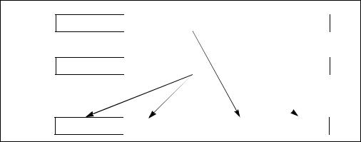
INSTRUCTION SET REFERENCE, N-Z
SHUFPS—Shuffle Packed Single-Precision Floating-Point Values
|
|
64-Bit |
Compat/ |
|
Opcode |
Instruction |
Mode |
Leg Mode |
Description |
0F C6 /r ib |
SHUFPS xmm1, |
Valid |
Valid |
Shuffle packed single-precision |
|
xmm2/m128, imm8 |
|
|
floating-point values selected by |
|
|
|
|
imm8 from xmm1 and |
|
|
|
|
xmm1/m128 to xmm1. |
|
|
|
|
|
Description
Moves two of the four packed single-precision floating-point values from the destination operand (first operand) into the low quadword of the destination operand; moves two of the four packed single-precision floating-point values from the source operand (second operand) into to the high quadword of the destination operand (see Figure 4-14). The select operand (third operand) determines which values are moved to the destination operand.
DEST |
X3 |
X2 |
X1 |
X0 |
SRC |
Y3 |
Y2 |
Y1 |
Y0 |
DEST |
Y3 ... Y0 |
Y3 ... Y0 |
X3 ... X0 |
X3 ... X0 |
Figure 4-14. SHUFPS Shuffle Operation
The source operand can be an XMM register or a 128-bit memory location. The destination operand is an XMM register. The select operand is an 8-bit immediate: bits 0 and 1 select the value to be moved from the destination operand to the low doubleword of the result, bits 2 and 3 select the value to be moved from the destination operand to the second doubleword of the result, bits 4 and 5 select the value to be moved from the source operand to the third doubleword of the result, and bits 6 and 7 select the value to be moved from the source operand to the high doubleword of the result.
In 64-bit mode, using a REX prefix in the form of REX.R permits this instruction to access additional registers (XMM8-XMM15).
Vol. 2B 4-307
INSTRUCTION SET REFERENCE, N-Z
Operation
CASE (SELECT[1:0]) OF
0:DEST[31:0] ← DEST[31:0];
1:DEST[31:0] ← DEST[63:32];
2:DEST[31:0] ← DEST[95:64];
3:DEST[31:0] ← DEST[127:96];
ESAC;
CASE (SELECT[3:2]) OF
0:DEST[63:32] ← DEST[31:0];
1:DEST[63:32] ← DEST[63:32];
2:DEST[63:32] ← DEST[95:64];
3:DEST[63:32] ← DEST[127:96];
ESAC;
CASE (SELECT[5:4]) OF
0:DEST[95:64] ← SRC[31:0];
1:DEST[95:64] ← SRC[63:32];
2:DEST[95:64] ← SRC[95:64];
3:DEST[95:64] ← SRC[127:96];
ESAC;
CASE (SELECT[7:6]) OF
0:DEST[127:96] ← SRC[31:0];
1:DEST[127:96] ← SRC[63:32];
2:DEST[127:96] ← SRC[95:64];
3:DEST[127:96] ← SRC[127:96];
ESAC;
Intel C/C++ Compiler Intrinsic Equivalent
SHUFPS __m128 _mm_shuffle_ps(__m128 a, __m128 b, unsigned int imm8)
SIMD Floating-Point Exceptions
None.
Protected Mode Exceptions
#GP(0) |
For an illegal memory operand effective address in the CS, DS, |
|
ES, FS or GS segments. |
|
If a memory operand is not aligned on a 16-byte boundary, |
|
regardless of segment. |
#SS(0) |
For an illegal address in the SS segment. |
#PF(fault-code) |
For a page fault. |
4-308 Vol. 2B
|
INSTRUCTION SET REFERENCE, N-Z |
#NM |
If CR0.TS[bit 3] = 1. |
#UD |
If CR0.EM[bit 2] = 1. |
|
If CR4.OSFXSR[bit 9] = 0. |
|
If CPUID.01H:EDX.SSE[bit 25] = 0. |
Real-Address Mode Exceptions |
|
#GP(0) |
If a memory operand is not aligned on a 16-byte boundary, |
|
regardless of segment. |
|
If any part of the operand lies outside the effective address |
|
space from 0 to FFFFH. |
#NM |
If CR0.TS[bit 3] = 1. |
#UD |
If CR0.EM[bit 2] = 1. |
|
If CR4.OSFXSR[bit 9] = 0. |
|
If CPUID.01H:EDX.SSE[bit 25] = 0. |
Virtual-8086 Mode Exceptions
Same exceptions as in Real Address Mode #PF(fault-code) For a page fault.
Compatibility Mode Exceptions
Same exceptions as in Protected Mode.
64-Bit Mode Exceptions
#SS(0) |
If a memory address referencing the SS segment is in a non- |
|
canonical form. |
#GP(0) |
If memory operand is not aligned on a 16-byte boundary, |
|
regardless of segment. |
|
If the memory address is in a non-canonical form. |
#PF(fault-code) |
For a page fault. |
#NM |
If CR0.TS[bit 3] = 1. |
#UD |
If CR0.EM[bit 2] = 1. |
|
If CR4.OSFXSR[bit 9] = 0. |
|
If CPUID.01H:EDX.SSE[bit 25] = 0. |
Vol. 2B 4-309
INSTRUCTION SET REFERENCE, N-Z
SIDT—Store Interrupt Descriptor Table Register
|
|
|
Compat/ |
|
|
|
64-Bit |
Leg |
|
Opcode |
Instruction |
Mode |
Mode |
Description |
0F 01 /1 |
SIDT m |
Valid |
Valid |
Store IDTR to m. |
|
|
|
|
|
Description
Stores the content the interrupt descriptor table register (IDTR) in the destination operand. The destination operand specifies a 6-byte memory location.
In non-64-bit modes, if the operand-size attribute is 32 bits, the 16-bit limit field of the register is stored in the low 2 bytes of the memory location and the 32-bit base address is stored in the high 4 bytes. If the operand-size attribute is 16 bits, the limit is stored in the low 2 bytes and the 24-bit base address is stored in the third, fourth, and fifth byte, with the sixth byte filled with 0s.
In 64-bit mode, the operand size fixed at 8+2 bytes. The instruction stores 8-byte base and 2-byte limit values.
SIDT is only useful in operating-system software; however, it can be used in application programs without causing an exception to be generated. See “LGDT/LIDT—Load Global/Interrupt Descriptor Table Register” in Chapter 3, Intel® 64 and IA-32 Architectures Software Developer’s Manual, Volume 2A, for information on loading the GDTR and IDTR.
IA-32 Architecture Compatibility
The 16-bit form of SIDT is compatible with the Intel 286 processor if the upper 8 bits are not referenced. The Intel 286 processor fills these bits with 1s; the Pentium 4, Intel Xeon, P6 processor family, Pentium, Intel486, and Intel386 processors fill these bits with 0s.
Operation
IF instruction is SIDT THEN
IF OperandSize = 16 THEN
DEST[0:15] ← IDTR(Limit);
DEST[16:39] ← IDTR(Base); (* 24 bits of base address stored; *) DEST[40:47] ← 0;
ELSE IF (32-bit Operand Size) DEST[0:15] ← IDTR(Limit);
DEST[16:47] ← IDTR(Base); FI; (* Full 32-bit base address stored *) ELSE (* 64-bit Operand Size *)
4-310 Vol. 2B
INSTRUCTION SET REFERENCE, N-Z
DEST[0:15] ← IDTR(Limit);
DEST[16:79] ← IDTR(Base); (* Full 64-bit base address stored *)
FI;
FI;
Flags Affected
None.
Protected Mode Exceptions
#GP(0) |
If the destination is located in a non-writable segment. |
|
If a memory operand effective address is outside the CS, DS, |
|
ES, FS, or GS segment limit. |
|
If the DS, ES, FS, or GS register is used to access memory and it |
|
contains a NULL segment selector. |
#SS(0) |
If a memory operand effective address is outside the SS |
|
segment limit. |
#PF(fault-code) |
If a page fault occurs. |
#AC(0) |
If alignment checking is enabled and an unaligned memory |
|
reference is made while the current privilege level is 3. |
Real-Address Mode Exceptions
#GP |
If a memory operand effective address is outside the CS, DS, |
|
ES, FS, or GS segment limit. |
#SS |
If a memory operand effective address is outside the SS |
|
segment limit. |
Virtual-8086 Mode Exceptions
#GP(0) |
If a memory operand effective address is outside the CS, DS, |
|
ES, FS, or GS segment limit. |
#SS(0) |
If a memory operand effective address is outside the SS |
|
segment limit. |
#PF(fault-code) |
If a page fault occurs. |
#AC(0) |
If alignment checking is enabled and an unaligned memory |
|
reference is made. |
Compatibility Mode Exceptions
Same exceptions as in Protected Mode.
64-Bit Mode Exceptions
#SS(0) |
If a memory address referencing the SS segment is in a non- |
|
canonical form. |
Vol. 2B 4-311
INSTRUCTION SET REFERENCE, N-Z
#UD |
If the destination operand is a register. |
#GP(0) |
If the memory address is in a non-canonical form. |
#PF(fault-code) |
If a page fault occurs. |
#AC(0) |
If alignment checking is enabled and an unaligned memory |
|
reference is made while the current privilege level is 3. |
4-312 Vol. 2B
|
|
|
|
INSTRUCTION SET REFERENCE, N-Z |
SLDT—Store Local Descriptor Table Register |
|
|||
|
|
|
|
|
|
|
64-Bit |
Compat/ |
|
Opcode |
Instruction |
Mode |
Leg Mode |
Description |
0F 00 /0 |
SLDT r/m16 |
Valid |
Valid |
Stores segment selector from LDTR |
|
|
|
|
in r/m16. |
REX.W + 0F |
SLDT r64/m16 |
Valid |
Valid |
Stores segment selector from LDTR |
00 /0 |
|
|
|
in r64/m16. |
|
|
|
|
|
Description
Stores the segment selector from the local descriptor table register (LDTR) in the destination operand. The destination operand can be a general-purpose register or a memory location. The segment selector stored with this instruction points to the segment descriptor (located in the GDT) for the current LDT. This instruction can only be executed in protected mode.
Outside IA-32e mode, when the destination operand is a 32-bit register, the 16-bit segment selector is copied into the low-order 16 bits of the register. The high-order 16 bits of the register are cleared for the Pentium 4, Intel Xeon, and P6 family processors. They are undefined for Pentium, Intel486, and Intel386 processors. When the destination operand is a memory location, the segment selector is written to memory as a 16-bit quantity, regardless of the operand size.
In compatibility mode, when the destination operand is a 32-bit register, the 16-bit segment selector is copied into the low-order 16 bits of the register. The high-order 16 bits of the register are cleared. When the destination operand is a memory location, the segment selector is written to memory as a 16-bit quantity, regardless of the operand size.
In 64-bit mode, using a REX prefix in the form of REX.R permits access to additional registers (R8-R15). The behavior of SLDT with a 64-bit register is to zero-extend the 16-bit selector and store it in the register. If the destination is memory and operand size is 64, SLDT will write the 16-bit selector to memory as a 16-bit quantity, regardless of the operand size
Operation
DEST ← LDTR(SegmentSelector);
Flags Affected
None.
Protected Mode Exceptions
#GP(0) |
If the destination is located in a non-writable segment. |
Vol. 2B 4-313
INSTRUCTION SET REFERENCE, N-Z
|
If a memory operand effective address is outside the CS, DS, |
|
ES, FS, or GS segment limit. |
|
If the DS, ES, FS, or GS register is used to access memory and it |
|
contains a NULL segment selector. |
#SS(0) |
If a memory operand effective address is outside the SS |
|
segment limit. |
#PF(fault-code) |
If a page fault occurs. |
#AC(0) |
If alignment checking is enabled and an unaligned memory |
|
reference is made while the current privilege level is 3. |
Real-Address Mode Exceptions
#UD The SLDT instruction is not recognized in real-address mode.
Virtual-8086 Mode Exceptions
#UD The SLDT instruction is not recognized in virtual-8086 mode.
Compatibility Mode Exceptions
Same exceptions as in Protected Mode.
64-Bit Mode Exceptions
#SS(0) |
If a memory address referencing the SS segment is in a non- |
|
canonical form. |
#GP(0) |
If the memory address is in a non-canonical form. |
#PF(fault-code) |
If a page fault occurs. |
#AC(0) |
If alignment checking is enabled and an unaligned memory |
|
reference is made while the current privilege level is 3. |
4-314 Vol. 2B
|
|
|
|
INSTRUCTION SET REFERENCE, N-Z |
SMSW—Store Machine Status Word |
|
|||
|
|
|
|
|
|
|
64-Bit |
Compat/ |
|
Opcode |
Instruction |
Mode |
Leg Mode |
Description |
0F 01 /4 |
SMSW r/m16 |
Valid |
Valid |
Store machine status word to r/m16. |
0F 01 /4 |
SMSW |
Valid |
Valid |
Store machine status word in low-order |
|
r32/m16 |
|
|
16 bits of r32/m16; high-order 16 bits |
|
|
|
|
of r32 are undefined. |
REX.W + |
SMSW |
Valid |
Valid |
Store machine status word in low-order |
0F 01 /4 |
r64/m16 |
|
|
16 bits of r64/m16; high-order 16 bits |
|
|
|
|
of r32 are undefined. |
|
|
|
|
|
Description
Stores the machine status word (bits 0 through 15 of control register CR0) into the destination operand. The destination operand can be a general-purpose register or a memory location.
In non-64-bit modes, when the destination operand is a 32-bit register, the low-order 16 bits of register CR0 are copied into the low-order 16 bits of the register and the high-order 16 bits are undefined. When the destination operand is a memory location, the low-order 16 bits of register CR0 are written to memory as a 16-bit quantity, regardless of the operand size.
In 64-bit mode, the behavior of the SMSW instruction is defined by the following examples:
•SMSW r16 operand size 16, store CR0[15:0] in r16
•SMSW r32 operand size 32, zero-extend CR0[31:0], and store in r32
•SMSW r64 operand size 64, zero-extend CR0[63:0], and store in r64
•SMSW m16 operand size 16, store CR0[15:0] in m16
•SMSW m16 operand size 32, store CR0[15:0] in m16 (not m32)
•SMSW m16 operands size 64, store CR0[15:0] in m16 (not m64)
SMSW is only useful in operating-system software. However, it is not a privileged instruction and can be used in application programs. The is provided for compatibility with the Intel 286 processor. Programs and procedures intended to run on the Pentium 4, Intel Xeon, P6 family, Pentium, Intel486, and Intel386 processors should use the MOV (control registers) instruction to load the machine status word.
See “Changes to Instruction Behavior in VMX Non-Root Operation” in Chapter 21 of the Intel® 64 and IA-32 Architectures Software Developer’s Manual, Volume 3B, for more information about the behavior of this instruction in VMX non-root operation.
Vol. 2B 4-315
INSTRUCTION SET REFERENCE, N-Z
Operation
DEST ← CR0[15:0];
(* Machine status word *)
Flags Affected
None.
Protected Mode Exceptions
#GP(0) |
If the destination is located in a non-writable segment. |
|
If a memory operand effective address is outside the CS, DS, |
|
ES, FS, or GS segment limit. |
|
If the DS, ES, FS, or GS register is used to access memory and it |
|
contains a NULL segment selector. |
#SS(0) |
If a memory operand effective address is outside the SS |
|
segment limit. |
#PF(fault-code) |
If a page fault occurs. |
#AC(0) |
If alignment checking is enabled and an unaligned memory |
|
reference is made while the current privilege level is 3. |
Real-Address Mode Exceptions
#GP |
If a memory operand effective address is outside the CS, DS, |
|
ES, FS, or GS segment limit. |
#SS(0) |
If a memory operand effective address is outside the SS |
|
segment limit. |
Virtual-8086 Mode Exceptions
#GP(0) |
If a memory operand effective address is outside the CS, DS, |
|
ES, FS, or GS segment limit. |
#SS(0) |
If a memory operand effective address is outside the SS |
|
segment limit. |
#PF(fault-code) |
If a page fault occurs. |
#AC(0) |
If alignment checking is enabled and an unaligned memory |
|
reference is made. |
Compatibility Mode Exceptions
Same exceptions as in Protected Mode.
4-316 Vol. 2B
|
INSTRUCTION SET REFERENCE, N-Z |
64-Bit Mode Exceptions |
|
#SS(0) |
If a memory address referencing the SS segment is in a non- |
|
canonical form. |
#GP(0) |
If the memory address is in a non-canonical form. |
#PF(fault-code) |
If a page fault occurs. |
#AC(0) |
If alignment checking is enabled and an unaligned memory |
|
reference is made while the current privilege level is 3. |
Vol. 2B 4-317
INSTRUCTION SET REFERENCE, N-Z
SQRTPD—Compute Square Roots of Packed Double-Precision Floating-
Point Values
|
|
64-Bit |
Compat/ |
|
Opcode |
Instruction |
Mode |
Leg Mode |
Description |
66 0F 51 |
SQRTPD xmm1, |
Valid |
Valid |
Computes square roots of the |
/r |
xmm2/m128 |
|
|
packed double-precision floating- |
|
|
|
|
point values in xmm2/m128 and |
|
|
|
|
stores the results in xmm1. |
|
|
|
|
|
Description
Performs a SIMD computation of the square roots of the two packed double-precision floating-point values in the source operand (second operand) stores the packed double-precision floating-point results in the destination operand. The source operand can be an XMM register or a 128-bit memory location. The destination operand is an XMM register. See Figure 11-3 in the Intel® 64 and IA-32 Architectures Software Developer’s Manual, Volume 1, for an illustration of a SIMD double-preci- sion floating-point operation.
In 64-bit mode, using a REX prefix in the form of REX.R permits this instruction to access additional registers (XMM8-XMM15).
Operation
DEST[63:0] ← SQRT(SRC[63:0]);
DEST[127:64] ← SQRT(SRC[127:64]);
Intel C/C++ Compiler Intrinsic Equivalent
SQRTPD __m128d _mm_sqrt_pd (m128d a)
SIMD Floating-Point Exceptions
Invalid, Precision, Denormal.
Protected Mode Exceptions
#GP(0) |
For an illegal memory operand effective address in the CS, DS, |
|
ES, FS or GS segments. |
|
If a memory operand is not aligned on a 16-byte boundary, |
|
regardless of segment. |
#SS(0) |
For an illegal address in the SS segment. |
#PF(fault-code) |
For a page fault. |
#NM |
If CR0.TS[bit 3] = 1. |
4-318 Vol. 2B
|
INSTRUCTION SET REFERENCE, N-Z |
#XM |
If an unmasked SIMD floating-point exception and CR4.OSXM- |
|
MEXCPT[bit 10] = 1. |
#UD |
If an unmasked SIMD floating-point exception and CR4.OSXM- |
|
MEXCPT[bit 10] = 0. |
|
If CR0.EM[bit 2] = 1. |
|
If CR4.OSFXSR[bit 9] = 0.CR4.OSXMMEXCPT(bit 10) is 1. |
|
If CPUID.01H:EDX.SSE2[bit 26] = 0. |
Real-Address Mode Exceptions |
|
#GP(0) |
If a memory operand is not aligned on a 16-byte boundary, |
|
regardless of segment. |
|
If any part of the operand lies outside the effective address |
|
space from 0 to FFFFH. |
#NM |
If CR0.TS[bit 3] = 1. |
#XM |
If an unmasked SIMD floating-point exception and CR4.OSXM- |
|
MEXCPT[bit 10] = 1. |
#UD |
If an unmasked SIMD floating-point exception and CR4.OSXM- |
|
MEXCPT[bit 10] = 0. |
If CR0.EM[bit 2] = 1.
If CR4.OSFXSR[bit 9] = 0.
If CPUID.01H:EDX.SSE2[bit 26] = 0.
Virtual-8086 Mode Exceptions
Same exceptions as in Real Address Mode #PF(fault-code) For a page fault.
Compatibility Mode Exceptions
Same exceptions as in Protected Mode.
64-Bit Mode Exceptions
#SS(0) |
If a memory address referencing the SS segment is in a non- |
|
canonical form. |
#GP(0) |
If the memory address is in a non-canonical form. |
|
If memory operand is not aligned on a 16-byte boundary, |
|
regardless of segment. |
#PF(fault-code) |
For a page fault. |
#NM |
If CR0.TS[bit 3] = 1. |
#XM |
If an unmasked SIMD floating-point exception and CR4.OSXM- |
|
MEXCPT[bit 10] = 1. |
Vol. 2B 4-319
INSTRUCTION SET REFERENCE, N-Z
#UD |
If an unmasked SIMD floating-point exception and CR4.OSXM- |
|
MEXCPT[bit 10] = 0. |
|
If CR0.EM[bit 2] = 1. |
|
If CR4.OSFXSR[bit 9] = 0. |
|
If CPUID.01H:EDX.SSE2[bit 26] = 0. |
4-320 Vol. 2B
INSTRUCTION SET REFERENCE, N-Z
SQRTPS—Compute Square Roots of Packed Single-Precision Floating-
Point Values
|
|
64-Bit |
Compat/ |
|
Opcode |
Instruction |
Mode |
Leg Mode |
Description |
0F 51 /r |
SQRTPS xmm1, |
Valid |
Valid |
Computes square roots of the packed |
|
xmm2/m128 |
|
|
single-precision floating-point values |
|
|
|
|
in xmm2/m128 and stores the results |
|
|
|
|
in xmm1. |
|
|
|
|
|
Description
Performs a SIMD computation of the square roots of the four packed single-precision floating-point values in the source operand (second operand) stores the packed single-precision floating-point results in the destination operand. The source operand can be an XMM register or a 128-bit memory location. The destination operand is an XMM register. See Figure 10-5 in the Intel® 64 and IA-32 Architectures Software Developer’s Manual, Volume 1, for an illustration of a SIMD single-precision floatingpoint operation.
In 64-bit mode, using a REX prefix in the form of REX.R permits this instruction to access additional registers (XMM8-XMM15).
Operation
DEST[31:0] ← SQRT(SRC[31:0]);
DEST[63:32] ← SQRT(SRC[63:32]);
DEST[95:64] ← SQRT(SRC[95:64]);
DEST[127:96] ← SQRT(SRC[127:96]);
Intel C/C++ Compiler Intrinsic Equivalent
SQRTPS __m128 _mm_sqrt_ps(__m128 a)
SIMD Floating-Point Exceptions
Invalid, Precision, Denormal.
Protected Mode Exceptions
#GP(0) |
For an illegal memory operand effective address in the CS, DS, |
|
ES, FS or GS segments. |
|
If a memory operand is not aligned on a 16-byte boundary, |
|
regardless of segment. |
#SS(0) |
For an illegal address in the SS segment. |
#PF(fault-code) |
For a page fault. |
Vol. 2B 4-321
INSTRUCTION SET REFERENCE, N-Z
#NM |
If CR0.TS[bit 3] = 1. |
#XM |
If an unmasked SIMD floating-point exception and CR4.OSXM- |
|
MEXCPT[bit 10] = 1. |
#UD |
If an unmasked SIMD floating-point exception and CR4.OSXM- |
|
MEXCPT[bit 10] = 0. |
|
If CR0.EM[bit 2] = 1. |
|
If CR4.OSFXSR[bit 9] = 0. |
|
If CPUID.01H:EDX.SSE[bit 25] = 0. |
Real-Address Mode Exceptions
#GP(0) |
If a memory operand is not aligned on a 16-byte boundary, |
|
regardless of segment. |
|
If any part of the operand lies outside the effective address |
|
space from 0 to FFFFH. |
#NM |
If CR0.TS[bit 3] = 1. |
#XM |
If an unmasked SIMD floating-point exception and CR4.OSXM- |
|
MEXCPT[bit 10] = 1. |
#UD |
If an unmasked SIMD floating-point exception and CR4.OSXM- |
|
MEXCPT[bit 10] = 0. |
|
If CR0.EM[bit 2] = 1. |
|
If CR4.OSFXSR[bit 9] = 0. |
|
If CPUID.01H:EDX.SSE[bit 25] = 0. |
Virtual-8086 Mode Exceptions
Same exceptions as in Real Address Mode #PF(fault-code) For a page fault.
Compatibility Mode Exceptions
Same exceptions as in Protected Mode.
64-Bit Mode Exceptions
#SS(0) |
If a memory address referencing the SS segment is in a non- |
|
canonical form. |
#GP(0) |
If the memory address is in a non-canonical form. |
|
If memory operand is not aligned on a 16-byte boundary, |
|
regardless of segment. |
#PF(fault-code) |
For a page fault. |
#NM |
If CR0.TS[bit 3] = 1. |
#XM |
If an unmasked SIMD floating-point exception and CR4.OSXM- |
|
MEXCPT[bit 10] = 1. |
4-322 Vol. 2B
|
INSTRUCTION SET REFERENCE, N-Z |
#UD |
If an unmasked SIMD floating-point exception and CR4.OSXM- |
|
MEXCPT[bit 10] = 0. |
|
If CR0.EM[bit 2] = 1. |
|
If CR4.OSFXSR[bit 9] = 0. |
|
If CPUID.01H:EDX.SSE[bit 25] = 0. |
Vol. 2B 4-323
INSTRUCTION SET REFERENCE, N-Z
SQRTSD—Compute Square Root of Scalar Double-Precision Floating-
Point Value
|
|
64-Bit |
Compat/ |
|
Opcode |
Instruction |
Mode |
Leg Mode |
Description |
F2 0F 51 |
SQRTSD xmm1, |
Valid |
Valid |
Computes square root of the |
/r |
xmm2/m64 |
|
|
low double-precision floating- |
|
|
|
|
point value in xmm2/m64 and |
|
|
|
|
stores the results in xmm1. |
|
|
|
|
|
Description
Computes the square root of the low double-precision floating-point value in the source operand (second operand) and stores the double-precision floating-point result in the destination operand. The source operand can be an XMM register or a 64-bit memory location. The destination operand is an XMM register. The high quadword of the destination operand remains unchanged. See Figure 11-4 in the Intel® 64 and IA-32 Architectures Software Developer’s Manual, Volume 1, for an illustration of a scalar double-precision floating-point operation.
In 64-bit mode, using a REX prefix in the form of REX.R permits this instruction to access additional registers (XMM8-XMM15).
Operation
DEST[63:0] ← SQRT(SRC[63:0]); (* DEST[127:64] unchanged *)
Intel C/C++ Compiler Intrinsic Equivalent
SQRTSD __m128d _mm_sqrt_sd (m128d a)
SIMD Floating-Point Exceptions
Invalid, Precision, Denormal.
Protected Mode Exceptions
#GP(0) |
For an illegal memory operand effective address in the CS, DS, |
|
ES, FS or GS segments. |
#SS(0) |
For an illegal address in the SS segment. |
#PF(fault-code) |
For a page fault. |
#NM |
If CR0.TS[bit 3] = 1. |
#XM |
If an unmasked SIMD floating-point exception and CR4.OSXM- |
|
MEXCPT[bit 10] = 1. |
4-324 Vol. 2B
|
INSTRUCTION SET REFERENCE, N-Z |
#UD |
If an unmasked SIMD floating-point exception and CR4.OSXM- |
|
MEXCPT[bit 10] = 0. |
|
If CR0.EM[bit 2] = 1. |
|
If CR4.OSFXSR[bit 9] = 0. |
|
If CPUID.01H:EDX.SSE2[bit 26] = 0. |
#AC(0) |
If alignment checking is enabled and an unaligned memory |
|
reference is made while the current privilege level is 3. |
Real-Address Mode Exceptions |
|
GP(0) |
If any part of the operand lies outside the effective address |
|
space from 0 to FFFFH. |
#NM |
If CR0.TS[bit 3] = 1. |
#XM |
If an unmasked SIMD floating-point exception and CR4.OSXM- |
|
MEXCPT[bit 10] = 1. |
#UD |
If an unmasked SIMD floating-point exception and CR4.OSXM- |
MEXCPT[bit 10] = 0.
If CR0.EM[bit 2] = 1.
If CR4.OSFXSR[bit 9] = 0.
If CPUID.01H:EDX.SSE2[bit 26] = 0.
Virtual-8086 Mode Exceptions
Same exceptions as in Real Address Mode
#PF(fault-code) |
For a page fault. |
#AC(0) |
If alignment checking is enabled and an unaligned memory |
|
reference is made. |
Compatibility Mode Exceptions
Same exceptions as in Protected Mode.
64-Bit Mode Exceptions
#SS(0) |
If a memory address referencing the SS segment is in a non- |
|
canonical form. |
#GP(0) |
If the memory address is in a non-canonical form. |
#PF(fault-code) |
For a page fault. |
#NM |
If CR0.TS[bit 3] = 1. |
#XM |
If an unmasked SIMD floating-point exception and CR4.OSXM- |
|
MEXCPT[bit 10] = 1. |
Vol. 2B 4-325
INSTRUCTION SET REFERENCE, N-Z
#UD |
If an unmasked SIMD floating-point exception and CR4.OSXM- |
|
MEXCPT[bit 10] = 0. |
|
If CR0.EM[bit 2] = 1. |
|
If CR4.OSFXSR[bit 9] = 0. |
|
If CPUID.01H:EDX.SSE2[bit 26] = 0. |
#AC(0) |
If alignment checking is enabled and an unaligned memory |
|
reference is made while the current privilege level is 3. |
4-326 Vol. 2B
INSTRUCTION SET REFERENCE, N-Z
SQRTSS—Compute Square Root of Scalar Single-Precision Floating-
Point Value
|
|
64-Bit |
Compat/ |
|
Opcode |
Instruction |
Mode |
Leg Mode |
Description |
F3 0F 51 |
SQRTSS xmm1, |
Valid |
Valid |
Computes square root of the low |
/r |
xmm2/m32 |
|
|
single-precision floating-point |
|
|
|
|
value in xmm2/m32 and stores |
|
|
|
|
the results in xmm1. |
|
|
|
|
|
Description
Computes the square root of the low single-precision floating-point value in the source operand (second operand) and stores the single-precision floating-point result in the destination operand. The source operand can be an XMM register or a 32-bit memory location. The destination operand is an XMM register. The three highorder doublewords of the destination operand remain unchanged. See Figure 10-6 in the Intel® 64 and IA-32 Architectures Software Developer’s Manual, Volume 1, for an illustration of a scalar single-precision floating-point operation.
In 64-bit mode, using a REX prefix in the form of REX.R permits this instruction to access additional registers (XMM8-XMM15).
Operation
DEST[31:0] ← SQRT (SRC[31:0]); (* DEST[127:64] unchanged *)
Intel C/C++ Compiler Intrinsic Equivalent
SQRTSS __m128 _mm_sqrt_ss(__m128 a)
SIMD Floating-Point Exceptions
Invalid, Precision, Denormal.
Protected Mode Exceptions
#GP(0) |
For an illegal memory operand effective address in the CS, DS, |
|
ES, FS or GS segments. |
#SS(0) |
For an illegal address in the SS segment. |
#PF(fault-code) |
For a page fault. |
#NM |
If CR0.TS[bit 3] = 1. |
#XM |
If an unmasked SIMD floating-point exception and CR4.OSXM- |
|
MEXCPT[bit 10] = 1. |
Vol. 2B 4-327
INSTRUCTION SET REFERENCE, N-Z
#UD |
If an unmasked SIMD floating-point exception and CR4.OSXM- |
|
MEXCPT[bit 10] = 0. |
|
If CR0.EM[bit 2] = 1. |
|
If CR4.OSFXSR[bit 9] = 0. |
|
If CPUID.01H:EDX.SSE[bit 25] = 0. |
#AC(0) |
If alignment checking is enabled and an unaligned memory |
|
reference is made while the current privilege level is 3. |
Real-Address Mode Exceptions
GP(0) |
If any part of the operand lies outside the effective address |
|
space from 0 to FFFFH. |
#NM |
If CR0.TS[bit 3] = 1. |
#XM |
If an unmasked SIMD floating-point exception and CR4.OSXM- |
|
MEXCPT[bit 10] = 1. |
#UD |
If an unmasked SIMD floating-point exception and CR4.OSXM- |
|
MEXCPT[bit 10] = 0. |
|
If CR0.EM[bit 2] = 1. |
|
If CR4.OSFXSR[bit 9] = 0. |
|
If CPUID.01H:EDX.SSE[bit 25] = 0. |
Virtual-8086 Mode Exceptions
Same exceptions as in Real Address Mode
#PF(fault-code) |
For a page fault. |
#AC(0) |
If alignment checking is enabled and an unaligned memory |
|
reference is made. |
Compatibility Mode Exceptions
Same exceptions as in Protected Mode.
64-Bit Mode Exceptions
#SS(0) |
If a memory address referencing the SS segment is in a non- |
|
canonical form. |
#GP(0) |
If the memory address is in a non-canonical form. |
#PF(fault-code) |
For a page fault. |
#NM |
If CR0.TS[bit 3] = 1. |
#XM |
If an unmasked SIMD floating-point exception and CR4.OSXM- |
|
MEXCPT[bit 10] = 1. |
4-328 Vol. 2B
|
INSTRUCTION SET REFERENCE, N-Z |
#UD |
If an unmasked SIMD floating-point exception and CR4.OSXM- |
|
MEXCPT[bit 10] = 0. |
|
If CR0.EM[bit 2] = 1. |
|
If CR4.OSFXSR[bit 9] = 0. |
|
If CPUID.01H:EDX.SSE[bit 25] = 0. |
#AC(0) |
If alignment checking is enabled and an unaligned memory |
|
reference is made while the current privilege level is 3. |
Vol. 2B 4-329
INSTRUCTION SET REFERENCE, N-Z
STC—Set Carry Flag
|
|
64-Bit |
Compat/ |
|
Opcode |
Instruction |
Mode |
Leg Mode |
Description |
F9 |
STC |
Valid |
Valid |
Set CF flag. |
|
|
|
|
|
Description
Sets the CF flag in the EFLAGS register.
This instruction’s operation is the same in non-64-bit modes and 64-bit mode.
Operation
CF ← 1;
Flags Affected
The CF flag is set. The OF, ZF, SF, AF, and PF flags are unaffected.
Exceptions (All Operating Modes)
None.
4-330 Vol. 2B
|
|
|
|
INSTRUCTION SET REFERENCE, N-Z |
STD—Set Direction Flag |
|
|
|
|
|
|
|
|
|
|
|
64-Bit |
Compat/ |
|
Opcode |
Instruction |
Mode |
Leg Mode |
Description |
FD |
STD |
Valid |
Valid |
Set DF flag. |
|
|
|
|
|
Description
Sets the DF flag in the EFLAGS register. When the DF flag is set to 1, string operations decrement the index registers (ESI and/or EDI).
This instruction’s operation is the same in non-64-bit modes and 64-bit mode.
Operation
DF ← 1;
Flags Affected
The DF flag is set. The CF, OF, ZF, SF, AF, and PF flags are unaffected.
Exceptions (All Operating Modes)
None.
Vol. 2B 4-331

INSTRUCTION SET REFERENCE, N-Z
STI—Set Interrupt Flag
|
|
64-Bit |
Compat/ |
|
Opcode |
Instruction |
Mode |
Leg Mode |
Description |
FB |
STI |
Valid |
Valid |
Set interrupt flag; external, maskable |
|
|
|
|
interrupts enabled at the end of the |
|
|
|
|
next instruction. |
|
|
|
|
|
Description
If protected-mode virtual interrupts are not enabled, STI sets the interrupt flag (IF) in the EFLAGS register. After the IF flag is set, the processor begins responding to external, maskable interrupts after the next instruction is executed. The delayed effect of this instruction is provided to allow interrupts to be enabled just before returning from a procedure (or subroutine). For instance, if an STI instruction is followed by an RET instruction, the RET instruction is allowed to execute before external interrupts are recognized1. If the STI instruction is followed by a CLI instruction (which clears the IF flag), the effect of the STI instruction is negated.
The IF flag and the STI and CLI instructions do not prohibit the generation of exceptions and NMI interrupts. NMI interrupts (and SMIs) may be blocked for one macroinstruction following an STI.
When protected-mode virtual interrupts are enabled, CPL is 3, and IOPL is less than 3; STI sets the VIF flag in the EFLAGS register, leaving IF unaffected.
Table 4-4 indicates the action of the STI instruction depending on the processor’s mode of operation and the CPL/IOPL settings of the running program or procedure.
This instruction’s operation is the same in non-64-bit modes and 64-bit mode.
1.The STI instruction delays recognition of interrupts only if it is executed with EFLAGS.IF = 0. In a sequence of STI instructions, only the first instruction in the sequence is guaranteed to delay interrupts.
In the following instruction sequence, interrupts may be recognized before RET executes:
STI STI RET
4-332 Vol. 2B

|
|
|
|
|
|
INSTRUCTION SET REFERENCE, N-Z |
||
|
|
Table 4-4. Decision Table for STI Results |
|
|||||
|
|
|
|
|
|
|
|
|
PE |
VM |
IOPL |
CPL |
PVI |
VIP |
VME |
|
STI Result |
|
|
|
|
|
|
|
|
|
0 |
X |
X |
X |
X |
X |
X |
|
IF = 1 |
|
|
|
|
|
|
|
|
|
1 |
0 |
≥ CPL |
X |
X |
X |
X |
|
IF = 1 |
|
|
|
|
|
|
|
|
|
1 |
0 |
< CPL |
3 |
1 |
0 |
X |
|
VIF = 1 |
|
|
|
|
|
|
|
|
|
1 |
0 |
< CPL |
< 3 |
X |
X |
X |
|
GP Fault |
|
|
|
|
|
|
|
|
|
1 |
0 |
< CPL |
X |
0 |
X |
X |
|
GP Fault |
|
|
|
|
|
|
|
|
|
1 |
0 |
< CPL |
X |
X |
1 |
X |
|
GP Fault |
|
|
|
|
|
|
|
|
|
1 |
1 |
3 |
X |
X |
X |
X |
|
IF = 1 |
|
|
|
|
|
|
|
|
|
1 |
1 |
< 3 |
X |
X |
0 |
1 |
|
VIF = 1 |
|
|
|
|
|
|
|
|
|
1 |
1 |
< 3 |
X |
X |
1 |
X |
|
GP Fault |
|
|
|
|
|
|
|
|
|
1 |
1 |
< 3 |
X |
X |
X |
0 |
|
GP Fault |
|
|
|
|
|
|
|
|
|
NOTES:
X = This setting has no impact.
Operation
IF PE = 0 (* Executing in real-address mode *) THEN
IF ← 1; (* Set Interrupt Flag *)
ELSE (* Executing in protected mode or virtual-8086 mode *) IF VM =0 (* Executing in protected mode*)
THEN
IF IOPL ≥ CPL
THEN
IF ← 1; (* Set Interrupt Flag *)
ELSE
IF (IOPL < CPL) and (CPL = 3) and (VIP = 0) THEN
VIF ← 1; (* Set Virtual Interrupt Flag *) ELSE
#GP(0);
FI;
FI;
ELSE (* Executing in Virtual-8086 mode *) IF IOPL = 3
THEN
IF ← 1; (* Set Interrupt Flag *)
Vol. 2B 4-333
INSTRUCTION SET REFERENCE, N-Z
ELSE
IF ((IOPL < 3) and (VIP =0) and (VME =1)) THEN
VIF ← 1; (* Set Virtual Interrupt Flag *)
ELSE
#GP(0); (* Trap to virtual-8086 monitor *)
FI;)
FI;
FI;
FI;
Flags Affected
The IF flag is set to 1; or the VIF flag is set to 1.
Protected Mode Exceptions
#GP(0) |
If the CPL is greater (has less privilege) than the IOPL of the |
|
current program or procedure. |
Real-Address Mode Exceptions
None.
Virtual-8086 Mode Exceptions
#GP(0) |
If the CPL is greater (has less privilege) than the IOPL of the |
|
current program or procedure. |
Compatibility Mode Exceptions
Same exceptions as in Protected Mode.
64-Bit Mode Exceptions
Same exceptions as in Protected Mode.
4-334 Vol. 2B
|
|
|
|
INSTRUCTION SET REFERENCE, N-Z |
STMXCSR—Store MXCSR Register State |
|
|||
|
|
|
|
|
|
|
64- |
|
|
|
|
Bit |
Compat/ |
|
Opcode |
Instruction |
Mode |
Leg Mode |
Description |
0F AE /3 |
STMXCSR m32 |
Valid |
Valid |
Store contents of MXCSR register to |
|
|
|
|
m32. |
|
|
|
|
|
Description
Stores the contents of the MXCSR control and status register to the destination operand. The destination operand is a 32-bit memory location. The reserved bits in the MXCSR register are stored as 0s.
This instruction’s operation is the same in non-64-bit modes and 64-bit mode.
Operation
m32 ← MXCSR;
Intel C/C++ Compiler Intrinsic Equivalent
_mm_getcsr(void)
Exceptions
None.
Numeric Exceptions
None.
Protected Mode Exceptions
#GP(0) |
For an illegal memory operand effective address in the CS, DS, |
|
ES, FS, or GS segments. |
#SS(0) |
For an illegal address in the SS segment. |
#PF(fault-code) |
For a page fault. |
#UD |
If CR0.EM[bit 2] = 1. |
#NM |
If CR0.TS[bit 3] = 1. |
#AC |
For unaligned memory reference. To enable #AC exceptions, |
|
three conditions must be true: CR0.AM[bit 18] = 1, |
|
EFLAGS.AC[bit 18] = 1, current CPL = 3. |
#UD |
If CR4.OSFXSR[bit 9] = 0. |
|
If CPUID.01H:EDX.SSE[bit 25] = 0. |
Vol. 2B 4-335
INSTRUCTION SET REFERENCE, N-Z
Real Address Mode Exceptions
GP(0) |
If any part of the operand would lie outside of the effective |
|
address space from 0 to 0FFFFH. |
#UD |
If CR0.EM[bit 2] = 1. |
#NM |
If CR0.TS[bit 3] = 1. |
#UD |
If CR4.OSFXSR[bit 9] = 0. |
|
If CPUID.01H:EDX.SSE[bit 25] = 0. |
Virtual 8086 Mode Exceptions
Same exceptions as in Real Address Mode.
#PF(fault-code) |
For a page fault. |
#AC |
For unaligned memory reference. |
Compatibility Mode Exceptions
Same exceptions as in Protected Mode.
64-Bit Mode Exceptions
#SS(0) |
If a memory address referencing the SS segment is in a non- |
|
canonical form. |
#GP(0) |
If the memory address is in a non-canonical form. |
#PF(fault-code) |
For a page fault. |
#UD |
If CR0.EM[bit 2] = 1. |
#NM |
If CR0.TS[bit 3] = 1. |
#AC |
For unaligned memory reference. To enable #AC exceptions, |
|
three conditions must be true: CR0.AM[bit 18] = 1, |
|
EFLAGS.AC[bit 18] = 1, current CPL = 3 |
#UD |
If CR4.OSFXSR[bit 9] = 0. |
#UD |
If CPUID.01H:EDX.SSE[bit 25] = 0. |
4-336 Vol. 2B
|
|
|
|
INSTRUCTION SET REFERENCE, N-Z |
STOS/STOSB/STOSW/STOSD/STOSQ—Store String |
||||
|
|
|
|
|
|
|
64-Bit |
Compat/ |
|
Opcode |
Instruction |
Mode |
Leg Mode |
Description |
AA |
STOS m8 |
Valid |
Valid |
For legacy mode, store AL at address |
|
|
|
|
ES:(E)DI; For 64-bit mode store AL at |
|
|
|
|
address RDI or EDI. |
AB |
STOS m16 |
Valid |
Valid |
For legacy mode, store AX at address |
|
|
|
|
ES:(E)DI; For 64-bit mode store AX at |
|
|
|
|
address RDI or EDI. |
AB |
STOS m32 |
Valid |
Valid |
For legacy mode, store EAX at address |
|
|
|
|
ES:(E)DI; For 64-bit mode store EAX at |
|
|
|
|
address RDI or EDI. |
REX.W + AB |
STOS m64 |
Valid |
N.E. |
Store RAX at address RDI or EDI. |
AA |
STOSB |
Valid |
Valid |
For legacy mode, store AL at address |
|
|
|
|
ES:(E)DI; For 64-bit mode store AL at |
|
|
|
|
address RDI or EDI. |
AB |
STOSW |
Valid |
Valid |
For legacy mode, store AX at address |
|
|
|
|
ES:(E)DI; For 64-bit mode store AX at |
|
|
|
|
address RDI or EDI. |
AB |
STOSD |
Valid |
Valid |
For legacy mode, store EAX at address |
|
|
|
|
ES:(E)DI; For 64-bit mode store EAX at |
|
|
|
|
address RDI or EDI. |
REX.W + AB |
STOSQ |
Valid |
N.E. |
Store RAX at address RDI or EDI. |
|
|
|
|
|
Description
In non-64-bit and default 64-bit mode; stores a byte, word, or doubleword from the AL, AX, or EAX register (respectively) into the destination operand. The destination operand is a memory location, the address of which is read from either the ES:EDI or ES:DI register (depending on the address-size attribute of the instruction and the mode of operation). The ES segment cannot be overridden with a segment override prefix.
At the assembly-code level, two forms of the instruction are allowed: the “explicitoperands” form and the “no-operands” form. The explicit-operands form (specified with the STOS mnemonic) allows the destination operand to be specified explicitly.
Here, the destination operand should be a symbol that indicates the size and location of the destination value. The source operand is then automatically selected to match the size of the destination operand (the AL register for byte operands, AX for word operands, EAX for doubleword operands). The explicit-operands form is provided to allow documentation; however, note that the documentation provided by this form can be misleading. That is, the destination operand symbol must specify the correct type (size) of the operand (byte, word, or doubleword), but it does not have to specify the correct location. The location is always specified by the ES:(E)DI
Vol. 2B 4-337
INSTRUCTION SET REFERENCE, N-Z
register. These must be loaded correctly before the store string instruction is executed.
The no-operands form provides “short forms” of the byte, word, doubleword, and quadword versions of the STOS instructions. Here also ES:(E)DI is assumed to be the destination operand and AL, AX, or EAX is assumed to be the source operand. The size of the destination and source operands is selected by the mnemonic: STOSB (byte read from register AL), STOSW (word from AX), STOSD (doubleword from EAX).
After the byte, word, or doubleword is transferred from the register to the memory location, the (E)DI register is incremented or decremented according to the setting of the DF flag in the EFLAGS register. If the DF flag is 0, the register is incremented; if the DF flag is 1, the register is decremented (the register is incremented or decremented by 1 for byte operations, by 2 for word operations, by 4 for doubleword operations).
In 64-bit mode, the default address size is 64 bits, 32-bit address size is supported using the prefix 67H. Using a REX prefix in the form of REX.W promotes operation on doubleword operand to 64 bits. The promoted no-operand mnemonic is STOSQ.
STOSQ (and its explicit operands variant) store a quadword from the RAX register into the destination addressed by RDI or EDI. See the summary chart at the beginning of this section for encoding data and limits.
The STOS, STOSB, STOSW, STOSD, STOSQ instructions can be preceded by the REP prefix for block loads of ECX bytes, words, or doublewords. More often, however, these instructions are used within a LOOP construct because data needs to be moved into the AL, AX, or EAX register before it can be stored. See “REP/REPE/REPZ/REPNE/REPNZ—Repeat String Operation Prefix” in this chapter for a description of the REP prefix.
Operation
Non-64-bit Mode:
IF (Byte store)
THEN
DEST ← AL;
THEN IF DF = 0
THEN (E)DI ← (E)DI + 1;
ELSE (E)DI ← (E)DI – 1;
FI;
ELSE IF (Word store)
THEN
DEST ← AX;
THEN IF DF = 0
THEN (E)DI ← (E)DI + 2;
ELSE (E)DI ← (E)DI – 2;
4-338 Vol. 2B
INSTRUCTION SET REFERENCE, N-Z
FI;
FI;
ELSE IF (Doubleword store)
THEN
DEST ← EAX;
THEN IF DF = 0
THEN (E)DI ← (E)DI + 4;
ELSE (E)DI ← (E)DI – 4;
FI;
FI;
FI;
64-bit Mode:
IF (Byte store)
THEN
DEST ← AL;
THEN IF DF = 0
THEN (R|E)DI ← (R|E)DI + 1;
ELSE (R|E)DI ← (R|E)DI – 1;
FI;
ELSE IF (Word store)
THEN
DEST ← AX;
THEN IF DF = 0
THEN (R|E)DI ← (R|E)DI + 2;
ELSE (R|E)DI ← (R|E)DI – 2;
FI;
FI;
ELSE IF (Doubleword store)
THEN
DEST ← EAX;
THEN IF DF = 0
THEN (R|E)DI ← (R|E)DI + 4;
ELSE (R|E)DI ← (R|E)DI – 4;
FI;
FI;
ELSE IF (Quadword store using REX.W )
THEN
DEST ← RAX;
THEN IF DF = 0
THEN (R|E)DI ← (R|E)DI + 8;
ELSE (R|E)DI ← (R|E)DI – 8;
FI;
Vol. 2B 4-339
INSTRUCTION SET REFERENCE, N-Z
FI;
FI;
Flags Affected
None.
Protected Mode Exceptions
#GP(0) |
If the destination is located in a non-writable segment. |
|
If a memory operand effective address is outside the limit of the |
|
ES segment. |
|
If the ES register contains a NULL segment selector. |
#PF(fault-code) |
If a page fault occurs. |
#AC(0) |
If alignment checking is enabled and an unaligned memory |
|
reference is made while the current privilege level is 3. |
Real-Address Mode Exceptions
#GP |
If a memory operand effective address is outside the ES |
|
segment limit. |
Virtual-8086 Mode Exceptions
#GP(0) |
If a memory operand effective address is outside the ES |
|
segment limit. |
#PF(fault-code) |
If a page fault occurs. |
#AC(0) |
If alignment checking is enabled and an unaligned memory |
|
reference is made. |
Compatibility Mode Exceptions
Same exceptions as in Protected Mode.
64-Bit Mode Exceptions
#GP(0) |
If the memory address is in a non-canonical form. |
#PF(fault-code) |
If a page fault occurs. |
#AC(0) |
If alignment checking is enabled and an unaligned memory |
|
reference is made while the current privilege level is 3. |
4-340 Vol. 2B
|
|
|
|
INSTRUCTION SET REFERENCE, N-Z |
STR—Store Task Register |
|
|
|
|
|
|
|
|
|
|
|
64-Bit |
Compat/ |
|
Opcode |
Instruction |
Mode |
Leg Mode |
Description |
0F 00 /1 |
STR r/m16 |
Valid |
Valid |
Stores segment selector from TR |
|
|
|
|
in r/m16. |
|
|
|
|
|
Description
Stores the segment selector from the task register (TR) in the destination operand. The destination operand can be a general-purpose register or a memory location. The segment selector stored with this instruction points to the task state segment (TSS) for the currently running task.
When the destination operand is a 32-bit register, the 16-bit segment selector is copied into the lower 16 bits of the register and the upper 16 bits of the register are cleared. When the destination operand is a memory location, the segment selector is written to memory as a 16-bit quantity, regardless of operand size.
In 64-bit mode, operation is the same. The size of the memory operand is fixed at 16 bits. In register stores, the 2-byte TR is zero extended if stored to a 64-bit register.
The STR instruction is useful only in operating-system software. It can only be executed in protected mode.
Operation
DEST ← TR(SegmentSelector);
Flags Affected
None.
Protected Mode Exceptions
#GP(0) |
If the destination is a memory operand that is located in a non- |
|
writable segment or if the effective address is outside the CS, |
|
DS, ES, FS, or GS segment limit. |
|
If the DS, ES, FS, or GS register is used to access memory and it |
|
contains a NULL segment selector. |
#SS(0) |
If a memory operand effective address is outside the SS |
|
segment limit. |
#PF(fault-code) |
If a page fault occurs. |
#AC(0) |
If alignment checking is enabled and an unaligned memory |
|
reference is made while the current privilege level is 3. |
Vol. 2B 4-341
INSTRUCTION SET REFERENCE, N-Z
Real-Address Mode Exceptions
#UD The STR instruction is not recognized in real-address mode.
Virtual-8086 Mode Exceptions
#UD The STR instruction is not recognized in virtual-8086 mode.
Compatibility Mode Exceptions
Same exceptions as in Protected Mode.
64-Bit Mode Exceptions
#GP(0) |
If the memory address is in a non-canonical form. |
#SS(U) |
If the stack address is in a non-canonical form. |
#PF(fault-code) |
If a page fault occurs. |
#AC(0) |
If alignment checking is enabled and an unaligned memory |
|
reference is made while the current privilege level is 3. |
4-342 Vol. 2B

INSTRUCTION SET REFERENCE, N-Z
SUB—Subtract
|
|
|
64-Bit |
Compat/ |
|
Opcode |
Instruction |
Mode |
Leg Mode |
Description |
|
2C ib |
SUB AL, imm8 |
Valid |
Valid |
Subtract imm8 from AL. |
|
2D iw |
SUB AX, imm16 |
Valid |
Valid |
Subtract imm16 from AX. |
|
2D id |
SUB EAX, imm32 |
Valid |
Valid |
Subtract imm32 from EAX. |
|
REX.W + 2D id |
SUB RAX, imm32 |
Valid |
N.E. |
Subtract imm32 sign- |
|
|
|
|
|
|
extended to 64-bits from |
|
|
|
|
|
RAX. |
80 |
/5 ib |
SUB r/m8, imm8 |
Valid |
Valid |
Subtract imm8 from r/m8. |
REX + 80 /5 ib |
SUB r/m8*, imm8 |
Valid |
N.E. |
Subtract imm8 from r/m8. |
|
81 |
/5 iw |
SUB r/m16, |
Valid |
Valid |
Subtract imm16 from |
|
|
imm16 |
|
|
r/m16. |
81 |
/5 id |
SUB r/m32, |
Valid |
Valid |
Subtract imm32 from |
|
|
imm32 |
|
|
r/m32. |
REX.W + 81 /5 id |
SUB r/m64, |
Valid |
N.E. |
Subtract imm32 sign- |
|
|
|
imm32 |
|
|
extended to 64-bits from |
|
|
|
|
|
r/m64. |
83 |
/5 ib |
SUB r/m16, imm8 |
Valid |
Valid |
Subtract sign-extended |
|
|
|
|
|
imm8 from r/m16. |
83 |
/5 ib |
SUB r/m32, imm8 |
Valid |
Valid |
Subtract sign-extended |
|
|
|
|
|
imm8 from r/m32. |
REX.W + 83 /5 ib |
SUB r/m64, imm8 |
Valid |
N.E. |
Subtract sign-extended |
|
|
|
|
|
|
imm8 from r/m64. |
28 |
/r |
SUB r/m8, r8 |
Valid |
Valid |
Subtract r8 from r/m8. |
REX + 28 /r |
SUB r/m8*, r8* |
Valid |
N.E. |
Subtract r8 from r/m8. |
|
29 |
/r |
SUB r/m16, r16 |
Valid |
Valid |
Subtract r16 from r/m16. |
29 |
/r |
SUB r/m32, r32 |
Valid |
Valid |
Subtract r32 from r/m32. |
REX.W + 29 /r |
SUB r/m64, r32 |
Valid |
N.E. |
Subtract r64 from r/m64. |
|
2A /r |
SUB r8, r/m8 |
Valid |
Valid |
Subtract r/m8 from r8. |
|
REX + 2A /r |
SUB r8*, r/m8* |
Valid |
N.E. |
Subtract r/m8 from r8. |
|
2B |
/r |
SUB r16, r/m16 |
Valid |
Valid |
Subtract r/m16 from r16. |
2B |
/r |
SUB r32, r/m32 |
Valid |
Valid |
Subtract r/m32 from r32. |
REX.W + 2B /r |
SUB r64, r/m64 |
Valid |
N.E. |
Subtract r/m64 from r64. |
|
NOTES:
*In 64-bit mode, r/m8 can not be encoded to access the following byte registers if a REX prefix is used: AH, BH, CH, DH.
Vol. 2B 4-343
INSTRUCTION SET REFERENCE, N-Z
Description
Subtracts the second operand (source operand) from the first operand (destination operand) and stores the result in the destination operand. The destination operand can be a register or a memory location; the source operand can be an immediate, register, or memory location. (However, two memory operands cannot be used in one instruction.) When an immediate value is used as an operand, it is sign-extended to the length of the destination operand format.
The SUB instruction performs integer subtraction. It evaluates the result for both signed and unsigned integer operands and sets the OF and CF flags to indicate an overflow in the signed or unsigned result, respectively. The SF flag indicates the sign of the signed result.
In 64-bit mode, the instruction’s default operation size is 32 bits. Using a REX prefix in the form of REX.R permits access to additional registers (R8-R15). Using a REX prefix in the form of REX.W promotes operation to 64 bits. See the summary chart at the beginning of this section for encoding data and limits.
This instruction can be used with a LOCK prefix to allow the instruction to be executed atomically.
Operation
DEST ← (DEST – SRC);
Flags Affected
The OF, SF, ZF, AF, PF, and CF flags are set according to the result.
Protected Mode Exceptions
#GP(0) |
If the destination is located in a non-writable segment. |
|
If a memory operand effective address is outside the CS, DS, |
|
ES, FS, or GS segment limit. |
|
If the DS, ES, FS, or GS register contains a NULL segment |
|
selector. |
#SS(0) |
If a memory operand effective address is outside the SS |
|
segment limit. |
#PF(fault-code) |
If a page fault occurs. |
#AC(0) |
If alignment checking is enabled and an unaligned memory |
|
reference is made while the current privilege level is 3. |
Real-Address Mode Exceptions
#GP |
If a memory operand effective address is outside the CS, DS, |
|
ES, FS, or GS segment limit. |
#SS |
If a memory operand effective address is outside the SS |
|
segment limit. |
4-344 Vol. 2B
|
INSTRUCTION SET REFERENCE, N-Z |
Virtual-8086 Mode Exceptions |
|
#GP(0) |
If a memory operand effective address is outside the CS, DS, |
|
ES, FS, or GS segment limit. |
#SS(0) |
If a memory operand effective address is outside the SS |
|
segment limit. |
#PF(fault-code) |
If a page fault occurs. |
#AC(0) |
If alignment checking is enabled and an unaligned memory |
|
reference is made. |
Compatibility Mode Exceptions
Same exceptions as in Protected Mode.
64-Bit Mode Exceptions
#SS(0) |
If a memory address referencing the SS segment is in a non- |
|
canonical form. |
#GP(0) |
If the memory address is in a non-canonical form. |
#PF(fault-code) |
If a page fault occurs. |
#AC(0) |
If alignment checking is enabled and an unaligned memory |
|
reference is made while the current privilege level is 3. |
Vol. 2B 4-345
INSTRUCTION SET REFERENCE, N-Z
SUBPD—Subtract Packed Double-Precision Floating-Point Values
|
|
64-Bit |
Compat/ |
|
Opcode |
Instruction |
Mode |
Leg Mode |
Description |
66 0F 5C |
SUBPD xmm1, |
Valid |
Valid |
Subtract packed double-precision |
/r |
xmm2/m128 |
|
|
floating-point values in |
|
|
|
|
xmm2/m128 from xmm1. |
|
|
|
|
|
Description
Performs a SIMD subtract of the two packed double-precision floating-point values in the source operand (second operand) from the two packed double-precision floatingpoint values in the destination operand (first operand), and stores the packed double-precision floating-point results in the destination operand. The source operand can be an XMM register or a 128-bit memory location. The destination operand is an XMM register. See Figure 11-3 in the Intel® 64 and IA-32 Architectures Software Developer’s Manual, Volume 1, for an illustration of a SIMD double-preci- sion floating-point operation.
In 64-bit mode, using a REX prefix in the form of REX.R permits this instruction to access additional registers (XMM8-XMM15).
Operation
DEST[63:0] ← DEST[63:0] − SRC[63:0];
DEST[127:64] ← DEST[127:64] − SRC[127:64];
Intel C/C++ Compiler Intrinsic Equivalent
SUBPD __m128d _mm_sub_pd (m128d a, m128d b)
SIMD Floating-Point Exceptions
Overflow, Underflow, Invalid, Precision, Denormal.
Protected Mode Exceptions
#GP(0) |
For an illegal memory operand effective address in the CS, DS, |
|
ES, FS or GS segments. |
|
If a memory operand is not aligned on a 16-byte boundary, |
|
regardless of segment. |
#SS(0) |
For an illegal address in the SS segment. |
#PF(fault-code) |
For a page fault. |
#NM |
If CR0.TS[bit 3] = 1. |
#XM |
If an unmasked SIMD floating-point exception and CR4.OSXM- |
|
MEXCPT[bit 10] = 1. |
4-346 Vol. 2B
|
INSTRUCTION SET REFERENCE, N-Z |
#UD |
If an unmasked SIMD floating-point exception and CR4.OSXM- |
|
MEXCPT[bit 10] = 0. |
|
If CR0.EM[bit 2] = 1. |
|
If CR4.OSFXSR[bit 9] = 1. |
|
If CPUID.01H:EDX.SSE2[bit 26] = 0. |
Real-Address Mode Exceptions |
|
#GP(0) |
If a memory operand is not aligned on a 16-byte boundary, |
|
regardless of segment. |
|
If any part of the operand lies outside the effective address |
|
space from 0 to FFFFH. |
#NM |
If CR0.TS[bit 3] = 1. |
#XM |
If an unmasked SIMD floating-point exception and CR4.OSXM- |
|
MEXCPT[bit 10] = 1. |
#UD |
If an unmasked SIMD floating-point exception and CR4.OSXM- |
MEXCPT[bit 10] = 0.
If CR0.EM[bit 2] = 1.
If CR4.OSFXSR[bit 9] = 0.
If CPUID.01H:EDX.SSE2[bit 26] = 0.
Virtual-8086 Mode Exceptions
Same exceptions as in Real Address Mode #PF(fault-code) For a page fault.
Compatibility Mode Exceptions
Same exceptions as in Protected Mode.
64-Bit Mode Exceptions
#SS(0) |
If a memory address referencing the SS segment is in a non- |
|
canonical form. |
#GP(0) |
If the memory address is in a non-canonical form. |
|
If memory operand is not aligned on a 16-byte boundary, |
|
regardless of segment. |
#PF(fault-code) |
For a page fault. |
#NM |
If CR0.TS[bit 3] = 1. |
#XM |
If an unmasked SIMD floating-point exception and CR4.OSXM- |
|
MEXCPT[bit 10] = 1. |
Vol. 2B 4-347
INSTRUCTION SET REFERENCE, N-Z
#UD |
If an unmasked SIMD floating-point exception and CR4.OSXM- |
|
MEXCPT[bit 10] = 0. |
|
If CR0.EM[bit 2] = 1. |
|
If CR4.OSFXSR[bit 9] = 0. |
|
If CPUID.01H:EDX.SSE2[bit 26] = 0. |
4-348 Vol. 2B
INSTRUCTION SET REFERENCE, N-Z
SUBPS—Subtract Packed Single-Precision Floating-Point Values
|
|
64-Bit |
Compat/ |
|
Opcode |
Instruction |
Mode |
Leg Mode |
Description |
0F 5C /r |
SUBPS xmm1 |
Valid |
Valid |
Subtract packed single-precision |
|
xmm2/m128 |
|
|
floating-point values in xmm2/mem |
|
|
|
|
from xmm1. |
|
|
|
|
|
Description
Performs a SIMD subtract of the four packed single-precision floating-point values in the source operand (second operand) from the four packed single-precision floatingpoint values in the destination operand (first operand), and stores the packed singleprecision floating-point results in the destination operand. The source operand can be an XMM register or a 128-bit memory location. The destination operand is an XMM register. See Figure 10-5 in the Intel® 64 and IA-32 Architectures Software Developer’s Manual, Volume 1, for an illustration of a SIMD double-precision floating-point operation.
In 64-bit mode, using a REX prefix in the form of REX.R permits this instruction to access additional registers (XMM8-XMM15).
Operation
DEST[31:0] ← DEST[31:0] − SRC[31:0];
DEST[63:32] ← DEST[63:32] − SRC[63:32];
DEST[95:64] ← DEST[95:64] − SRC[95:64];
DEST[127:96] ← DEST[127:96] − SRC[127:96];
Intel C/C++ Compiler Intrinsic Equivalent
SUBPS __m128 _mm_sub_ps(__m128 a, __m128 b)
SIMD Floating-Point Exceptions
Overflow, Underflow, Invalid, Precision, Denormal.
Protected Mode Exceptions
#GP(0) |
For an illegal memory operand effective address in the CS, DS, |
|
ES, FS or GS segments. |
|
If a memory operand is not aligned on a 16-byte boundary, |
|
regardless of segment. |
#SS(0) |
For an illegal address in the SS segment. |
#PF(fault-code) |
For a page fault. |
#NM |
If CR0.TS[bit 3] = 1. |
Vol. 2B 4-349
INSTRUCTION SET REFERENCE, N-Z
#XM |
If an unmasked SIMD floating-point exception and CR4.OSXM- |
|
MEXCPT[bit 10] = 1. |
#UD |
If an unmasked SIMD floating-point exception and CR4.OSXM- |
|
MEXCPT[bit 10] = 0. |
|
If CR0.EM[bit 2] = 1. |
|
If CR4.OSFXSR[bit 9] = 0. |
|
If CPUID.01H:EDX.SSE[bit 25] = 0. |
Real-Address Mode Exceptions
#GP(0) |
If a memory operand is not aligned on a 16-byte boundary, |
|
regardless of segment. |
|
If any part of the operand lies outside the effective address |
|
space from 0 to FFFFH. |
#NM |
If CR0.TS[bit 3] = 1. |
#XM |
If an unmasked SIMD floating-point exception and CR4.OSXM- |
|
MEXCPT[bit 10] = 1. |
#UD |
If an unmasked SIMD floating-point exception and CR4.OSXM- |
|
MEXCPT[bit 10] = 0. |
|
If CR0.EM[bit 2] = 1. |
|
If CR4.OSFXSR[bit 9] = 0. |
|
If CPUID.01H:EDX.SSE[bit 25] = 0. |
Virtual-8086 Mode Exceptions
Same exceptions as in Real Address Mode #PF(fault-code) For a page fault.
Compatibility Mode Exceptions
Same exceptions as in Protected Mode.
64-Bit Mode Exceptions
#SS(0) |
If a memory address referencing the SS segment is in a non- |
|
canonical form. |
#GP(0) |
If the memory address is in a non-canonical form. |
|
If memory operand is not aligned on a 16-byte boundary, |
|
regardless of segment. |
#PF(fault-code) |
For a page fault. |
#NM |
If CR0.TS[bit 3] = 1. |
#XM |
If an unmasked SIMD floating-point exception and CR4.OSXM- |
|
MEXCPT[bit 10] = 1. |
4-350 Vol. 2B
|
INSTRUCTION SET REFERENCE, N-Z |
#UD |
If an unmasked SIMD floating-point exception and CR4.OSXM- |
|
MEXCPT[bit 10] = 0. |
|
If CR0.EM[bit 2] = 1. |
|
If CR4.OSFXSR[bit 9] = 0. |
|
If CPUID.01H:EDX.SSE[bit 25] = 0. |
Vol. 2B 4-351
INSTRUCTION SET REFERENCE, N-Z
SUBSD—Subtract Scalar Double-Precision Floating-Point Values
|
|
64-Bit |
Compat/ |
|
Opcode |
Instruction |
Mode |
Leg Mode |
Description |
F2 0F 5C |
SUBSD xmm1, |
Valid |
Valid |
Subtracts the low double- |
/r |
xmm2/m64 |
|
|
precision floating-point values in |
|
|
|
|
xmm2/mem64 from xmm1. |
|
|
|
|
|
Description
Subtracts the low double-precision floating-point value in the source operand (second operand) from the low double-precision floating-point value in the destination operand (first operand), and stores the double-precision floating-point result in the destination operand. The source operand can be an XMM register or a 64-bit memory location. The destination operand is an XMM register. The high quadword of the destination operand remains unchanged. See Figure 11-4 in the Intel® 64 and IA-32 Architectures Software Developer’s Manual, Volume 1, for an illustration of a scalar double-precision floating-point operation.
In 64-bit mode, using a REX prefix in the form of REX.R permits this instruction to access additional registers (XMM8-XMM15).
Operation
DEST[63:0] ← DEST[63:0] − SRC[63:0]; (* DEST[127:64] unchanged *)
Intel C/C++ Compiler Intrinsic Equivalent
SUBSD __m128d _mm_sub_sd (m128d a, m128d b)
SIMD Floating-Point Exceptions
Overflow, Underflow, Invalid, Precision, Denormal.
Protected Mode Exceptions
#GP(0) |
For an illegal memory operand effective address in the CS, DS, |
|
ES, FS or GS segments. |
#SS(0) |
For an illegal address in the SS segment. |
#PF(fault-code) |
For a page fault. |
#NM |
If CR0.TS[bit 3] = 1. |
#XM |
If an unmasked SIMD floating-point exception and CR4.OSXM- |
|
MEXCPT[bit 10] = 1. |
4-352 Vol. 2B
|
INSTRUCTION SET REFERENCE, N-Z |
#UD |
If an unmasked SIMD floating-point exception and CR4.OSXM- |
|
MEXCPT[bit 10] = 0. |
|
If CR0.EM[bit 2] = 1. |
|
If CR4.OSFXSR[bit 9] = 0. |
|
If CPUID.01H:EDX.SSE2[bit 26] = 0. |
#AC(0) |
If alignment checking is enabled and an unaligned memory |
|
reference is made while the current privilege level is 3. |
Real-Address Mode Exceptions |
|
GP(0) |
If any part of the operand lies outside the effective address |
|
space from 0 to FFFFH. |
#NM |
If CR0.TS[bit 3] = 1. |
#XM |
If an unmasked SIMD floating-point exception and CR4.OSXM- |
|
MEXCPT[bit 10] = 1. |
#UD |
If an unmasked SIMD floating-point exception and CR4.OSXM- |
MEXCPT[bit 10] = 0.
If CR0.EM[bit 2] = 1.
If CR4.OSFXSR[bit 9] = 0.
If CPUID.01H:EDX.SSE2[bit 26] = 0.
Virtual-8086 Mode Exceptions
Same exceptions as in Real Address Mode
#PF(fault-code) |
For a page fault. |
#AC(0) |
If alignment checking is enabled and an unaligned memory |
|
reference is made. |
Compatibility Mode Exceptions
Same exceptions as in Protected Mode.
64-Bit Mode Exceptions
#SS(0) |
If a memory address referencing the SS segment is in a non- |
|
canonical form. |
#GP(0) |
If the memory address is in a non-canonical form. |
#PF(fault-code) |
For a page fault. |
#NM |
If CR0.TS[bit 3] = 1. |
#XM |
If an unmasked SIMD floating-point exception and CR4.OSXM- |
|
MEXCPT[bit 10] = 1. |
Vol. 2B 4-353
INSTRUCTION SET REFERENCE, N-Z
#UD |
If an unmasked SIMD floating-point exception and CR4.OSXM- |
|
MEXCPT[bit 10] = 0. |
|
If CR0.EM[bit 2] = 1. |
|
If CR4.OSFXSR[bit 9] = 0. |
|
If CPUID.01H:EDX.SSE2[bit 26] = 0. |
#AC(0) |
If alignment checking is enabled and an unaligned memory |
|
reference is made while the current privilege level is 3. |
4-354 Vol. 2B
INSTRUCTION SET REFERENCE, N-Z
SUBSS—Subtract Scalar Single-Precision Floating-Point Values
|
|
|
Compat/ |
|
|
|
64-Bit |
Leg |
|
Opcode |
Instruction |
Mode |
Mode |
Description |
F3 0F 5C /r |
SUBSS xmm1, |
Valid |
Valid |
Subtract the lower single-precision |
|
xmm2/m32 |
|
|
floating-point values in |
|
|
|
|
xmm2/m32 from xmm1. |
|
|
|
|
|
Description
Subtracts the low single-precision floating-point value in the source operand (second operand) from the low single-precision floating-point value in the destination operand (first operand), and stores the single-precision floating-point result in the destination operand. The source operand can be an XMM register or a 32-bit memory location. The destination operand is an XMM register. The three high-order doublewords of the destination operand remain unchanged. See Figure 10-6 in the Intel® 64 and IA-32 Architectures Software Developer’s Manual, Volume 1, for an illustration of a scalar single-precision floating-point operation.
In 64-bit mode, using a REX prefix in the form of REX.R permits this instruction to access additional registers (XMM8-XMM15).
Operation
DEST[31:0] ← DEST[31:0] − SRC[31:0]; (* DEST[127:96] unchanged *)
Intel C/C++ Compiler Intrinsic Equivalent
SUBSS __m128 _mm_sub_ss(__m128 a, __m128 b)
SIMD Floating-Point Exceptions
Overflow, Underflow, Invalid, Precision, Denormal.
Protected Mode Exceptions
#GP(0) |
For an illegal memory operand effective address in the CS, DS, |
|
ES, FS or GS segments. |
#SS(0) |
For an illegal address in the SS segment. |
#PF(fault-code) |
For a page fault. |
#NM |
If CR0.TS[bit 3] = 1. |
#XM |
If an unmasked SIMD floating-point exception and CR4.OSXM- |
|
MEXCPT[bit 10] = 1. |
Vol. 2B 4-355
INSTRUCTION SET REFERENCE, N-Z
#UD |
If an unmasked SIMD floating-point exception and CR4.OSXM- |
|
MEXCPT[bit 10] = 0. |
|
If CR0.EM[bit 2] = 1. |
|
If CR4.OSFXSR[bit 9] = 0. |
|
If CPUID.01H:EDX.SSE[bit 25] = 0. |
#AC(0) |
If alignment checking is enabled and an unaligned memory |
|
reference is made while the current privilege level is 3. |
Real-Address Mode Exceptions
GP(0) |
If any part of the operand lies outside the effective address |
|
space from 0 to FFFFH. |
#NM |
If CR0.TS[bit 3] = 1. |
#XM |
If an unmasked SIMD floating-point exception and CR4.OSXM- |
|
MEXCPT[bit 10] = 1. |
#UD |
If an unmasked SIMD floating-point exception and CR4.OSXM- |
|
MEXCPT[bit 10] = 0. |
|
If CR0.EM[bit 2] = 1. |
|
If CR4.OSFXSR[bit 9] = 0. |
|
If CPUID.01H:EDX.SSE[bit 25] = 0. |
Virtual-8086 Mode Exceptions
Same exceptions as in Real Address Mode
#PF(fault-code) |
For a page fault. |
#AC(0) |
If alignment checking is enabled and an unaligned memory |
|
reference is made. |
Compatibility Mode Exceptions
Same exceptions as in Protected Mode.
64-Bit Mode Exceptions
#SS(0) |
If a memory address referencing the SS segment is in a non- |
|
canonical form. |
#GP(0) |
If the memory address is in a non-canonical form. |
#PF(fault-code) |
For a page fault. |
#NM |
If CR0.TS[bit 3] = 1. |
#XM |
If an unmasked SIMD floating-point exception and CR4.OSXM- |
|
MEXCPT[bit 10] = 1. |
4-356 Vol. 2B
|
INSTRUCTION SET REFERENCE, N-Z |
#UD |
If an unmasked SIMD floating-point exception and CR4.OSXM- |
|
MEXCPT[bit 10] = 0. |
|
If CR0.EM[bit 2] = 1. |
|
If CR4.OSFXSR[bit 9] = 0. |
|
If CPUID.01H:EDX.SSE[bit 25] = 0. |
#AC(0) |
If alignment checking is enabled and an unaligned memory |
|
reference is made while the current privilege level is 3. |
Vol. 2B 4-357
INSTRUCTION SET REFERENCE, N-Z
SWAPGS—Swap GS Base Register
|
|
64-Bit |
Compat/ |
|
Opcode |
Instruction |
Mode |
Leg Mode |
Description |
0F 01 /7 |
SWAPGS |
Valid |
Invalid |
Exchanges the current GS base |
|
|
|
|
register value with the value |
|
|
|
|
contained in MSR address |
|
|
|
|
C0000102H. |
|
|
|
|
|
Description
SWAPGS exchanges the current GS base register value with the value contained in MSR address C0000102H (MSR_KERNELGSbase). KernelGSbase is guaranteed to be canonical; so SWAPGS does not perform a canonical check. The SWAPGS instruction is a privileged instruction intended for use by system software.
When using SYSCALL to implement system calls, there is no kernel stack at the OS entry point. Neither is there a straightforward method to obtain a pointer to kernel structures from which the kernel stack pointer could be read. Thus, the kernel can't save general purpose registers or reference memory.
By design, SWAPGS does not require any general purpose registers or memory operands. No registers need to be saved before using the instruction. SWAPGS exchanges the CPL 0 data pointer from the KernelGSbase MSR with the GS base register. The kernel can then use the GS prefix on normal memory references to access kernel data structures. Similarly, when the OS kernel is entered using an interrupt or exception (where the kernel stack is already set up), SWAPGS can be used to quickly get a pointer to the kernel data structures.
The KernelGSbase MSR itself is only accessible using RDMSR/WRMSR instructions. Those instructions are only accessible at privilege level 0. WRMSR will cause a #GP(0) if the value to be written to KernelGSbase MSR is non-canonical.
See Table 4-5.
Table 4-5. SWAPGS Operation Parameters
Opcode |
|
ModR/M Byte |
|
Instruction |
||
|
|
|
|
|
|
|
|
MOD |
REG |
|
R/M |
Not 64-bit |
64-bit Mode |
|
|
|
|
|
Mode |
|
|
|
|
|
|
|
|
OF 01 |
MOD ≠11 |
111 |
|
xxx |
INVLPG |
INVLPG |
|
|
|
|
|
|
|
|
11 |
111 |
|
000 |
#UD |
SWPGS |
|
|
|
|
|
|
|
|
11 |
111 |
|
≠000 |
#UD |
#UD |
|
|
|
|
|
|
|
4-358 Vol. 2B
INSTRUCTION SET REFERENCE, N-Z
Operation
IF CS.L ≠ 1 (* Not in 64-Bit Mode *) THEN
#UD; FI;
IF CPL ≠0
THEN #GP(0); FI;
tmp ← GS(BASE);
GS(BASE) ← KERNELGSbase; KERNELGSbase ← tmp;
Flags Affected
None
Protected Mode Exceptions
#UD |
If Mode ≠64-Bit |
Real-Address Mode Exceptions |
|
#UD |
Instruction not recognized. |
Virtual-8086 Mode Exceptions |
|
#UD |
Instruction not recognized. |
Compatibility Mode Exceptions
Same exceptions as in Protected Mode.
64-Bit Mode Exceptions
#GP(0) |
If CPL ≠0. |
Vol. 2B 4-359
INSTRUCTION SET REFERENCE, N-Z
SYSCALL—Fast System Call
|
|
64-Bit |
Compat/ |
|
Opcode |
Instruction |
Mode |
Leg Mode |
Description |
0F 05 |
SYSCALL |
Valid |
Invalid |
Fast call to privilege level 0 |
|
|
|
|
system procedures. |
|
|
|
|
|
Description
SYSCALL saves the RIP of the instruction following SYSCALL to RCX and loads a new RIP from the IA32_LSTAR (64-bit mode). Upon return, SYSRET copies the value saved in RCX to the RIP.
SYSCALL saves RFLAGS (lower 32 bit only) in R11. It then masks RFLAGS with an OS-defined value using the IA32_FMASK (MSR C000_0084). The actual mask value used by the OS is the complement of the value written to the IA32_FMASK MSR. None of the bits in RFLAGS are automatically cleared (except for RF). SYSRET restores RFLAGS from R11 (the lower 32 bits only).
Software should not alter the CS or SS descriptors in a manner that violates the following assumptions made by SYSCALL/SYSRET:
•The CS and SS base and limit remain the same for all processes, including the operating system (the base is 0H and the limit is 0FFFFFFFFH).
•The CS of the SYSCALL target has a privilege level of 0.
•The CS of the SYSRET target has a privilege level of 3.
SYSCALL/SYSRET do not check for violations of these assumptions.
Operation
IF (CS.L ≠ 1 ) or (IA32_EFER.LMA ≠1) or (IA32_EFER.SCE ≠1)
(* Not in 64-Bit Mode or SYSCALL/SYSRET not enabled in IA32_EFER *) THEN #UD; FI;
RCX ← RIP;
RIP ← LSTAR_MSR; R11 ← EFLAGS;
EFLAGS ← (EFLAGS MASKED BY IA32_FMASK); CPL ← 0;
CS(SEL) ← IA32_STAR_MSR[47:32]; CS(DPL) ← 0;
CS(BASE) ← 0; CS(LIMIT) ← 0xFFFFF; CS(GRANULAR) ← 1;
SS(SEL) ← IA32_STAR_MSR[47:32] + 8; SS(DPL) ← 0;
4-360 Vol. 2B
INSTRUCTION SET REFERENCE, N-Z
SS(BASE) ← 0;
SS(LIMIT) ← 0xFFFFF;
SS(GRANULAR) ← 1;
Flags Affected
All.
Protected Mode Exceptions
#UD |
If Mode ≠64-bit. |
Real-Address Mode Exceptions |
|
#UD |
Instruction is not recognized in this mode. |
Virtual-8086 Mode Exceptions |
|
#UD |
Instruction is not recognized in this mode. |
Compatibility Mode Exceptions |
|
#UD |
Instruction is not recognized in this mode. |
64-Bit Mode Exceptions |
|
#UD |
If IA32_EFER.SCE = 0. |
Vol. 2B 4-361
INSTRUCTION SET REFERENCE, N-Z
SYSENTER—Fast System Call
|
|
64-Bit |
Compat/ |
|
Opcode |
Instruction |
Mode |
Leg Mode |
Description |
0F 34 |
SYSENTER |
Valid |
Valid |
Fast call to privilege level 0 system |
|
|
|
|
procedures. |
|
|
|
|
|
Description
Executes a fast call to a level 0 system procedure or routine. SYSENTER is a companion instruction to SYSEXIT. The instruction is optimized to provide the maximum performance for system calls from user code running at privilege level 3 to operating system or executive procedures running at privilege level 0.
Prior to executing the SYSENTER instruction, software must specify the privilege level 0 code segment and code entry point, and the privilege level 0 stack segment and stack pointer by writing values to the following MSRs:
•IA32_SYSENTER_CS — Contains a 32-bit value, of which the lower 16 bits are the segment selector for the privilege level 0 code segment. This value is also used to compute the segment selector of the privilege level 0 stack segment.
•IA32_SYSENTER_EIP — Contains the 32-bit offset into the privilege level 0 code segment to the first instruction of the selected operating procedure or routine.
•IA32_SYSENTER_ESP — Contains the 32-bit stack pointer for the privilege level 0 stack.
These MSRs can be read from and written to using RDMSR/WRMSR. Register addresses are listed in Table 4-6. The addresses are defined to remain fixed for future Intel 64 and IA-32 processors.
Table 4-6. MSRs Used By the SYSENTER and SYSEXIT Instructions
MSR |
Address |
|
|
IA32_SYSENTER_CS |
174H |
|
|
IA32_SYSENTER_ESP |
175H |
|
|
IA32_SYSENTER_EIP |
176H |
|
|
When SYSENTER is executed, the processor:
1.Loads the segment selector from the IA32_SYSENTER_CS into the CS register.
2.Loads the instruction pointer from the IA32_SYSENTER_EIP into the EIP register.
3.Adds 8 to the value in IA32_SYSENTER_CS and loads it into the SS register.
4.Loads the stack pointer from the IA32_SYSENTER_ESP into the ESP register.
5.Switches to privilege level 0.
4-362 Vol. 2B
INSTRUCTION SET REFERENCE, N-Z
6.Clears the VM flag in the EFLAGS register, if the flag is set.
7.Begins executing the selected system procedure.
The processor does not save a return IP or other state information for the calling procedure.
The SYSENTER instruction always transfers program control to a protected-mode code segment with a DPL of 0. The instruction requires that the following conditions are met by the operating system:
•The segment descriptor for the selected system code segment selects a flat, 32-bit code segment of up to 4 GBytes, with execute, read, accessed, and nonconforming permissions.
•The segment descriptor for selected system stack segment selects a flat 32-bit stack segment of up to 4 GBytes, with read, write, accessed, and expand-up permissions.
The SYSENTER can be invoked from all operating modes except real-address mode.
The SYSENTER and SYSEXIT instructions are companion instructions, but they do not constitute a call/return pair. When executing a SYSENTER instruction, the processor does not save state information for the user code, and neither the SYSENTER nor the SYSEXIT instruction supports passing parameters on the stack.
To use the SYSENTER and SYSEXIT instructions as companion instructions for transitions between privilege level 3 code and privilege level 0 operating system procedures, the following conventions must be followed:
•The segment descriptors for the privilege level 0 code and stack segments and for the privilege level 3 code and stack segments must be contiguous in the global descriptor table. This convention allows the processor to compute the segment selectors from the value entered in the SYSENTER_CS_MSR MSR.
•The fast system call “stub” routines executed by user code (typically in shared libraries or DLLs) must save the required return IP and processor state information if a return to the calling procedure is required. Likewise, the operating system or executive procedures called with SYSENTER instructions must have access to and use this saved return and state information when returning to the user code.
The SYSENTER and SYSEXIT instructions were introduced into the IA-32 architecture in the Pentium II processor. The availability of these instructions on a processor is indicated with the SYSENTER/SYSEXIT present (SEP) feature flag returned to the EDX register by the CPUID instruction. An operating system that qualifies the SEP flag must also qualify the processor family and model to ensure that the SYSENTER/SYSEXIT instructions are actually present. For example:
IF CPUID SEP bit is set
THEN IF (Family = 6) and (Model < 3) and (Stepping < 3)
THEN
SYSENTER/SYSEXIT_Not_Supported; FI;
ELSE
Vol. 2B 4-363
INSTRUCTION SET REFERENCE, N-Z
SYSENTER/SYSEXIT_Supported; FI;
FI;
When the CPUID instruction is executed on the Pentium Pro processor (model 1), the processor returns a the SEP flag as set, but does not support the SYSENTER/SYSEXIT instructions.
Operation
IF CR0.PE = 0 THEN #GP(0); FI;
IF SYSENTER_CS_MSR[15:2] =0 THEN #GP(0); FI;
EFLAGS.VM ← 0; |
(* Insures protected mode execution *) |
EFLAGS.IF ← 0; |
(* Mask interrupts *) |
EFLAGS.RF ← 0; |
|
CS.SEL ← SYSENTER_CS_MSR |
(* Operating system provides CS *) |
(* Set rest of CS to a fixed value *) |
|
CS.BASE ← 0; |
(* Flat segment *) |
CS.LIMIT ← FFFFFH; |
(* 4-GByte limit *) |
CS.ARbyte.G ← 1; |
(* 4-KByte granularity *) |
CS.ARbyte.S ← 1; |
|
CS.ARbyte.TYPE ← 1011B; |
(* Execute + Read, Accessed *) |
CS.ARbyte.D ← 1; |
(* 32-bit code segment*) |
CS.ARbyte.DPL ← 0; |
|
CS.SEL.RPL ← 0; |
|
CS.ARbyte.P ← 1; |
|
CPL ← 0; |
|
SS.SEL ← CS.SEL + 8; |
|
(* Set rest of SS to a fixed value *) |
|
SS.BASE ← 0; |
(* Flat segment *) |
SS.LIMIT ← FFFFFH; |
(* 4-GByte limit *) |
SS.ARbyte.G ← 1; |
(* 4-KByte granularity *) |
SS.ARbyte.S ←; |
|
SS.ARbyte.TYPE ← 0011B; |
(* Read/Write, Accessed *) |
SS.ARbyte.D ← 1; |
(* 32-bit stack segment*) |
SS.ARbyte.DPL ← 0; |
|
SS.SEL.RPL ← 0; |
|
SS.ARbyte.P ← 1; |
|
ESP ← SYSENTER_ESP_MSR; |
|
EIP ← SYSENTER_EIP_MSR; |
|
4-364 Vol. 2B
INSTRUCTION SET REFERENCE, N-Z
IA-32e Mode Operation
In IA-32e mode, SYSENTER executes a fast system calls from user code running at privilege level 3 (in compatibility mode or 64-bit mode) to 64-bit executive procedures running at privilege level 0. This instruction is a companion instruction to the SYSEXIT instruction.
In IA-32e mode, the IA32_SYSENTER_EIP and IA32_SYSENTER_ESP MSRs hold 64-bit addresses and must be in canonical form; IA32_SYSENTER_CS must not contain a NULL selector.
When SYSENTER transfers control, the following fields are generated and bits set:
•Target code segment — Reads non-NULL selector from IA32_SYSENTER_CS.
•New CS attributes — L-bit = 1 (go to 64-bit mode); CS base = 0, CS limit = FFFFFFFFH.
•Target instruction — Reads 64-bit canonical address from IA32_SYSENTER_EIP.
•Stack segment — Computed by adding 8 to the value from IA32_SYSENTER_CS.
•Stack pointer — Reads 64-bit canonical address from IA32_SYSENTER_ESP.
•New SS attributes — SS base = 0, SS limit = FFFFFFFFH.
Flags Affected
VM, IF, RF (see Operation above)
Protected Mode Exceptions
#GP(0) If IA32_SYSENTER_CS[15:2] = 0.
Real-Address Mode Exceptions
#GP(0) If protected mode is not enabled.
Virtual-8086 Mode Exceptions
Same exceptions as in Protected Mode.
Compatibility Mode Exceptions
Same exceptions as in Protected Mode.
64-Bit Mode Exceptions
Same exceptions as in Protected Mode.
Vol. 2B 4-365
INSTRUCTION SET REFERENCE, N-Z
SYSEXIT—Fast Return from Fast System Call
|
|
64-Bit |
Compat/ |
|
Opcode |
Instruction |
Mode |
Leg Mode |
Description |
0F 35 |
SYSEXIT |
Valid |
Valid |
Fast return to privilege level 3 user code. |
REX.W + |
SYSEXIT |
Valid |
Valid |
Fast return to 64-bit mode privilege level |
0F 35 |
|
|
|
3 user code. |
|
|
|
|
|
Description
Executes a fast return to privilege level 3 user code. SYSEXIT is a companion instruction to the SYSENTER instruction. The instruction is optimized to provide the maximum performance for returns from system procedures executing at protections levels 0 to user procedures executing at protection level 3. It must be executed from code executing at privilege level 0.
Prior to executing SYSEXIT, software must specify the privilege level 3 code segment and code entry point, and the privilege level 3 stack segment and stack pointer by writing values into the following MSR and general-purpose registers:
•IA32_SYSENTER_CS — Contains a 32-bit value, of which the lower 16 bits are the segment selector for the privilege level 0 code segment in which the processor is currently executing. This value is used to compute the segment selectors for the privilege level 3 code and stack segments.
•EDX — Contains the 32-bit offset into the privilege level 3 code segment to the first instruction to be executed in the user code.
•ECX — Contains the 32-bit stack pointer for the privilege level 3 stack.
The IA32_SYSENTER_CS MSR can be read from and written to using RDMSR/WRMSR. The register address is listed in Table 4-6. This address is defined to remain fixed for future Intel 64 and IA-32 processors.
When SYSEXIT is executed, the processor:
1.Adds 16 to the value in IA32_SYSENTER_CS and loads the sum into the CS selector register.
2.Loads the instruction pointer from the EDX register into the EIP register.
3.Adds 24 to the value in IA32_SYSENTER_CS and loads the sum into the SS selector register.
4.Loads the stack pointer from the ECX register into the ESP register.
5.Switches to privilege level 3.
6.Begins executing the user code at the EIP address.
See “SWAPGS—Swap GS Base Register” in this chapter for information about using the SYSENTER and SYSEXIT instructions as companion call and return instructions.
4-366 Vol. 2B
INSTRUCTION SET REFERENCE, N-Z
The SYSEXIT instruction always transfers program control to a protected-mode code segment with a DPL of 3. The instruction requires that the following conditions are met by the operating system:
•The segment descriptor for the selected user code segment selects a flat, 32-bit code segment of up to 4 GBytes, with execute, read, accessed, and nonconforming permissions.
•The segment descriptor for selected user stack segment selects a flat, 32-bit stack segment of up to 4 GBytes, with expand-up, read, write, and accessed permissions.
The SYSENTER can be invoked from all operating modes except real-address mode and virtual 8086 mode.
The SYSENTER and SYSEXIT instructions were introduced into the IA-32 architecture in the Pentium II processor. The availability of these instructions on a processor is indicated with the SYSENTER/SYSEXIT present (SEP) feature flag returned to the EDX register by the CPUID instruction. An operating system that qualifies the SEP flag must also qualify the processor family and model to ensure that the SYSENTER/SYSEXIT instructions are actually present. For example:
IF CPUID SEP bit is set
THEN IF (Family = 6) and (Model < 3) and (Stepping < 3) THEN
SYSENTER/SYSEXIT_Not_Supported; FI; ELSE
SYSENTER/SYSEXIT_Supported; FI;
FI;
When the CPUID instruction is executed on the Pentium Pro processor (model 1), the processor returns a the SEP flag as set, but does not support the SYSENTER/SYSEXIT instructions.
Operation
IF SYSENTER_CS_MSR[15:2] = 0 THEN #GP(0); FI;
IF CR0.PE = 0 THEN #GP(0); FI;
IF CPL ≠ 0 THEN #GP(0); FI;
CS.SEL ← (SYSENTER_CS_MSR + 16); |
(* Segment selector for return CS *) |
(* Set rest of CS to a fixed value *) |
|
CS.BASE ← 0; |
(* Flat segment *) |
CS.LIMIT ← FFFFFH; |
(* 4-GByte limit *) |
CS.ARbyte.G ← 1; |
(* 4-KByte granularity *) |
CS.ARbyte.S ← 1; |
|
CS.ARbyte.TYPE ← 1011B; |
(* Execute, Read, Non-Conforming Code *) |
CS.ARbyte.D ← 1; |
(* 32-bit code segment*) |
CS.ARbyte.DPL ← 3; |
|
Vol. 2B 4-367
INSTRUCTION SET REFERENCE, N-Z |
|
CS.SEL.RPL ← 3; |
|
CS.ARbyte.P ← 1; |
|
CPL ← 3; |
|
SS.SEL ← (SYSENTER_CS_MSR + 24); |
(* Segment selector for return SS *) |
(* Set rest of SS to a fixed value *); |
|
SS.BASE ← 0; |
(* Flat segment *) |
SS.LIMIT ← FFFFFH; |
(* 4-GByte limit *) |
SS.ARbyte.G ←1; |
(* 4-KByte granularity *) |
SS.ARbyte.S ← ; |
|
SS.ARbyte.TYPE ← 0011B; |
(* Expand Up, Read/Write, Data *) |
SS.ARbyte.D ← 1; |
(* 32-bit stack segment*) |
SS.ARbyte.DPL ← 3; |
|
SS.SEL.RPL ← 3; |
|
SS.ARbyte.P ← 1; |
|
ESP ← ECX; |
|
EIP ← EDX; |
|
IA-32e Mode Operation
In IA-32e mode, SYSEXIT executes a fast system calls from a 64-bit executive procedures running at privilege level 0 to user code running at privilege level 3 (in compatibility mode or 64-bit mode). This instruction is a companion instruction to the SYSENTER instruction.
In IA-32e mode, the IA32_SYSENTER_EIP and IA32_SYSENTER_ESP MSRs hold 64-bit addresses and must be in canonical form; IA32_SYSENTER_CS must not contain a NULL selector.
When the SYSEXIT instruction transfers control to 64-bit mode user code using REX.W, the following fields are generated and bits set:
•Target code segment — Computed by adding 32 to the value in the IA32_SYSENTER_CS.
•New CS attributes — L-bit = 1 (go to 64-bit mode).
•Target instruction — Reads 64-bit canonical address in RDX.
•Stack segment — Computed by adding 8 to the value of CS selector.
•Stack pointer — Update RSP using 64-bit canonical address in RCX.
When SYSEXIT transfers control to compatibility mode user code when the operand size attribute is 32 bits, the following fields are generated and bits set:
•Target code segment — Computed by adding 16 to the value in IA32_SYSENTER_CS.
•New CS attributes — L-bit = 0 (go to compatibility mode).
•Target instruction — Fetch the target instruction from 32-bit address in EDX.
4-368 Vol. 2B
INSTRUCTION SET REFERENCE, N-Z
•Stack segment — Computed by adding 24 to the value in IA32_SYSENTER_CS.
•Stack pointer — Update ESP from 32-bit address in ECX.
Flags Affected
None.
Protected Mode Exceptions
#GP(0) |
If IA32_SYSENTER_CS[15:2] = 0. |
|
If CPL ≠0. |
Real-Address Mode Exceptions |
|
#GP(0) |
If protected mode is not enabled. |
Virtual-8086 Mode Exceptions
#GP(0) Always
Compatibility Mode Exceptions
Same exceptions as in Protected Mode.
64-Bit Mode Exceptions
#GP(0) |
If IA32_SYSENTER_CS = 0. |
|
If CPL ≠0. |
|
If ECX or EDX contains a non-canonical address. |
Vol. 2B 4-369
INSTRUCTION SET REFERENCE, N-Z
SYSRET—Return From Fast System Call
|
|
64-Bit |
Compat/ |
|
Opcode |
Instruction |
Mode |
Leg Mode |
Description |
0F 07 |
SYSRET |
Valid |
Invalid |
Return from fast system call |
|
|
|
|
|
Description
SYSCALL saves the RIP of the instruction following the SYSCALL into RCX and loads the new RIP from the LSTAR (64-bit mode only). Upon return, SYSRET copies the value saved in RCX to the RIP.
In a return to 64-bit mode using Osize 64, SYSRET sets the CS selector value to MSR IA32_STAR[63:48] +16. The SS is set to IA32_STAR[63:48] + 8.
SYSRET transfer control to compatibility mode using Osize 32. The CS selector value is set to MSR IA32_STAR[63:48]. The SS is set to IA32_STAR[63:48] + 8.
It is the responsibility of the OS to keep descriptors in the GDT/LDT that correspond to selectors loaded by SYSCALL/SYSRET consistent with the base, limit and attribute values forced by the these instructions.
Software should not alter the CS or SS descriptors in a manner that violates the following assumptions made by SYSCALL/SYSRET:
•CS and SS base and limit remain the same for all processes, including the operating system.
•CS of the SYSCALL target has a privilege level of 0.
•CS of the SYSRET target has a privilege level of 3.
SYSCALL/SYSRET do not check for violations of these assumptions.
Operation
IF (CS.L ≠ 1 ) or (IA32_EFER.LMA ≠1) or (IA32_EFER.SCE ≠1)
(* Not in 64-Bit Mode or SYSCALL/SYSRET not enabled in IA32_EFER *) THEN #UD; FI;
IF (CPL ≠ 0)
THEN #GP(0); FI;
IF (RCX ≠CANONICAL_ADDRESS) THEN #GP(0); FI;
IF (OPERAND_SIZE = 64)
THEN (* Return to 64-Bit Mode *) EFLAGS ← R11;
CPL ← 0x3;
CS(SEL) ← IA32_STAR[63:48] + 16; CS(PL) ← 0x3;
SS(SEL) ← IA32_STAR[63:48] + 8;
4-370 Vol. 2B
INSTRUCTION SET REFERENCE, N-Z
SS(PL) ← 0x3;
RIP ← RCX;
ELSE (* Return to Compatibility Mode *)
EFLAGS ← R11;
CPL ← 0x3;
CS(SEL) ← IA32_STAR[63:48] ;
CS(PL) ← 0x3;
SS(SEL) ← IA32_STAR[63:48] + 8;
SS(PL) ← 0x3;
EIP ← ECX;
FI;
Flags Affected
VM, IF, RF.
Protected Mode Exceptions
#UD |
If Mode ≠64-Bit. |
Real-Address Mode Exceptions |
|
#UD |
Instruction not recognized in this mode. |
Virtual-8086 Mode Exceptions |
|
#UD |
Instruction not recognized in this mode. |
Compatibility Mode Exceptions |
|
#UD |
Instruction not recognized in this mode. |
64-Bit Mode Exceptions |
|
#UD |
If IA32_EFER.SCE bit = 0. |
#GP(0) |
If CPL ≠0. |
|
If ECX contains a non-canonical address. |
Vol. 2B 4-371

INSTRUCTION SET REFERENCE, N-Z
TEST—Logical Compare
|
|
|
Compat/ |
|
|
|
64-Bit |
Leg |
|
Opcode |
Instruction |
Mode |
Mode |
Description |
A8 ib |
TEST AL, imm8 |
Valid |
Valid |
AND imm8 with AL; set SF, |
|
|
|
|
ZF, PF according to result. |
A9 iw |
TEST AX, imm16 |
Valid |
Valid |
AND imm16 with AX; set SF, |
|
|
|
|
ZF, PF according to result. |
A9 id |
TEST EAX, imm32 |
Valid |
Valid |
AND imm32 with EAX; set |
|
|
|
|
SF, ZF, PF according to |
|
|
|
|
result. |
REX.W + A9 id |
TEST RAX, imm32 |
Valid |
N.E. |
AND imm32 sign-extended |
|
|
|
|
to 64-bits with RAX; set SF, |
|
|
|
|
ZF, PF according to result. |
F6 /0 ib |
TEST r/m8, imm8 |
Valid |
Valid |
AND imm8 with r/m8; set SF, |
|
|
|
|
ZF, PF according to result. |
REX + F6 /0 ib |
TEST r/m8*, imm8 |
Valid |
N.E. |
AND imm8 with r/m8; set SF, |
|
|
|
|
ZF, PF according to result. |
F7 /0 iw |
TEST r/m16, |
Valid |
Valid |
AND imm16 with r/m16; set |
|
imm16 |
|
|
SF, ZF, PF according to |
|
|
|
|
result. |
F7 /0 id |
TEST r/m32, |
Valid |
Valid |
AND imm32 with r/m32; set |
|
imm32 |
|
|
SF, ZF, PF according to |
|
|
|
|
result. |
REX.W + F7 /0 id |
TEST r/m64, |
Valid |
N.E. |
AND imm32 sign-extended |
|
imm32 |
|
|
to 64-bits with r/m64; set |
|
|
|
|
SF, ZF, PF according to |
|
|
|
|
result. |
84 /r |
TEST r/m8, r8 |
Valid |
Valid |
AND r8 with r/m8; set SF, ZF, |
|
|
|
|
PF according to result. |
REX + 84 /r |
TEST r/m8*, r8* |
Valid |
N.E. |
AND r8 with r/m8; set SF, ZF, |
|
|
|
|
PF according to result. |
85 /r |
TEST r/m16, r16 |
Valid |
Valid |
AND r16 with r/m16; set SF, |
|
|
|
|
ZF, PF according to result. |
85 /r |
TEST r/m32, r32 |
Valid |
Valid |
AND r32 with r/m32; set SF, |
|
|
|
|
ZF, PF according to result. |
REX.W + 85 /r |
TEST r/m64, r64 |
Valid |
N.E. |
AND r64 with r/m64; set SF, |
|
|
|
|
ZF, PF according to result. |
NOTES:
*In 64-bit mode, r/m8 can not be encoded to access the following byte registers if a REX prefix is used: AH, BH, CH, DH.
4-372 Vol. 2B
INSTRUCTION SET REFERENCE, N-Z
Description
Computes the bit-wise logical AND of first operand (source 1 operand) and the second operand (source 2 operand) and sets the SF, ZF, and PF status flags according to the result. The result is then discarded.
In 64-bit mode, using a REX prefix in the form of REX.R permits access to additional registers (R8-R15). Using a REX prefix in the form of REX.W promotes operation to 64 bits. See the summary chart at the beginning of this section for encoding data and limits.
Operation
TEMP ← SRC1 AND SRC2;
SF ← MSB(TEMP);
IF TEMP = 0
THEN ZF ← 1;
ELSE ZF ← 0;
FI:
PF ← BitwiseXNOR(TEMP[0:7]); CF ← 0;
OF ← 0;
(* AF is undefined *)
Flags Affected
The OF and CF flags are set to 0. The SF, ZF, and PF flags are set according to the result (see the “Operation” section above). The state of the AF flag is undefined.
Protected Mode Exceptions
#GP(0) |
If a memory operand effective address is outside the CS, DS, |
|
ES, FS, or GS segment limit. |
|
If the DS, ES, FS, or GS register contains a NULL segment |
|
selector. |
#SS(0) |
If a memory operand effective address is outside the SS |
|
segment limit. |
#PF(fault-code) |
If a page fault occurs. |
#AC(0) |
If alignment checking is enabled and an unaligned memory |
|
reference is made while the current privilege level is 3. |
Vol. 2B 4-373
INSTRUCTION SET REFERENCE, N-Z
Real-Address Mode Exceptions
#GP |
If a memory operand effective address is outside the CS, DS, |
|
ES, FS, or GS segment limit. |
#SS |
If a memory operand effective address is outside the SS |
|
segment limit. |
Virtual-8086 Mode Exceptions
#GP(0) |
If a memory operand effective address is outside the CS, DS, |
|
ES, FS, or GS segment limit. |
#SS(0) |
If a memory operand effective address is outside the SS |
|
segment limit. |
#PF(fault-code) |
If a page fault occurs. |
#AC(0) |
If alignment checking is enabled and an unaligned memory |
|
reference is made. |
Compatibility Mode Exceptions
Same exceptions as in Protected Mode.
64-Bit Mode Exceptions
#SS(0) |
If a memory address referencing the SS segment is in a non- |
|
canonical form. |
#GP(0) |
If the memory address is in a non-canonical form. |
#PF(fault-code) |
If a page fault occurs. |
#AC(0) |
If alignment checking is enabled and an unaligned memory |
|
reference is made while the current privilege level is 3. |
4-374 Vol. 2B

INSTRUCTION SET REFERENCE, N-Z
UCOMISD—Unordered Compare Scalar Double-Precision Floating-Point
Values and Set EFLAGS
|
|
64-Bit |
Compat/ |
|
Opcode |
Instruction |
Mode |
Leg Mode |
Description |
66 0F 2E /r UCOMISD xmm1, |
Valid |
Valid |
Compares (unordered) the low |
|
|
xmm2/m64 |
|
|
double-precision floating-point |
|
|
|
|
values in xmm1 and xmm2/m64 and |
set the EFLAGS accordingly.
Description
Performs and unordered compare of the double-precision floating-point values in the low quadwords of source operand 1 (first operand) and source operand 2 (second operand), and sets the ZF, PF, and CF flags in the EFLAGS register according to the result (unordered, greater than, less than, or equal). The OF, SF and AF flags in the EFLAGS register are set to 0. The unordered result is returned if either source operand is a NaN (QNaN or SNaN).
Source operand 1 is an XMM register; source operand 2 can be an XMM register or a 64 bit memory location.
The UCOMISD instruction differs from the COMISD instruction in that it signals a SIMD floating-point invalid operation exception (#I) only when a source operand is an SNaN. The COMISD instruction signals an invalid operation exception if a source operand is either a QNaN or an SNaN.
The EFLAGS register is not updated if an unmasked SIMD floating-point exception is generated.
In 64-bit mode, using a REX prefix in the form of REX.R permits this instruction to access additional registers (XMM8-XMM15).
Operation
RESULT ← UnorderedCompare(SRC1[63:0] < > SRC2[63:0]) {
(* Set EFLAGS *) |
|
CASE (RESULT) OF |
|
UNORDERED: |
ZF, PF, CF ← 111; |
GREATER_THAN: |
ZF, PF, CF ← 000; |
LESS_THAN: |
ZF, PF, CF ← 001; |
EQUAL: |
ZF, PF, CF ← 100; |
ESAC; |
|
OF, AF, SF ← 0; |
|
Vol. 2B 4-375
INSTRUCTION SET REFERENCE, N-Z
Intel C/C++ Compiler Intrinsic Equivalent int_mm_ucomieq_sd(__m128d a, __m128d b) int_mm_ucomilt_sd(__m128d a, __m128d b) int_mm_ucomile_sd(__m128d a, __m128d b) int_mm_ucomigt_sd(__m128d a, __m128d b) int_mm_ucomige_sd(__m128d a, __m128d b) int_mm_ucomineq_sd(__m128d a, __m128d b)
SIMD Floating-Point Exceptions
Invalid (if SNaN operands), Denormal.
Protected Mode Exceptions
#GP(0) |
For an illegal memory operand effective address in the CS, DS, |
|
ES, FS or GS segments. |
#SS(0) |
For an illegal address in the SS segment. |
#PF(fault-code) |
For a page fault. |
#NM |
If CR0.TS[bit 3] = 1. |
#XM |
If an unmasked SIMD floating-point exception and CR4.OSXM- |
|
MEXCPT[bit 10] = 1. |
#UD |
If an unmasked SIMD floating-point exception and CR4.OSXM- |
|
MEXCPT[bit 10] = 0. |
|
If CR0.EM[bit 2] = 1. |
|
If CR4.OSFXSR[bit 9] = 0. |
|
If CPUID.01H:EDX.SSE2[bit 26] = 0. |
#AC(0) |
If alignment checking is enabled and an unaligned memory |
|
reference is made while the current privilege level is 3. |
Real-Address Mode Exceptions
GP(0) |
If any part of the operand lies outside the effective address |
|
space from 0 to FFFFH. |
#NM |
If CR0.TS[bit 3] = 1. |
#XM |
If an unmasked SIMD floating-point exception and CR4.OSXM- |
|
MEXCPT[bit 10] = 1. |
#UD |
If an unmasked SIMD floating-point exception and CR4.OSXM- |
|
MEXCPT[bit 10] = 0. |
|
If CR0.EM[bit 2] = 1. |
|
If CR4.OSFXSR[bit 9] = 0. |
|
If CPUID.01H:EDX.SSE2[bit 26] = 0. |
4-376 Vol. 2B
INSTRUCTION SET REFERENCE, N-Z
Virtual-8086 Mode Exceptions
Same exceptions as in Real Address Mode
#PF(fault-code) |
For a page fault. |
#AC(0) |
If alignment checking is enabled and an unaligned memory |
|
reference is made. |
Compatibility Mode Exceptions
Same exceptions as in Protected Mode.
64-Bit Mode Exceptions
#SS(0) |
If a memory address referencing the SS segment is in a non- |
|
canonical form. |
#GP(0) |
If the memory address is in a non-canonical form. |
#PF(fault-code) |
For a page fault. |
#NM |
If CR0.TS[bit 3] = 1. |
#XM |
If an unmasked SIMD floating-point exception and CR4.OSXM- |
|
MEXCPT[bit 10] = 1. |
#UD |
If an unmasked SIMD floating-point exception and CR4.OSXM- |
|
MEXCPT[bit 10] = 0. |
|
If CR0.EM[bit 2] = 1. |
|
If CR4.OSFXSR[bit 9] = 0. |
|
If CPUID.01H:EDX.SSE2[bit 26] = 0. |
#AC(0) |
If alignment checking is enabled and an unaligned memory |
|
reference is made while the current privilege level is 3. |
Vol. 2B 4-377
INSTRUCTION SET REFERENCE, N-Z
UCOMISS—Unordered Compare Scalar Single-Precision Floating-Point
Values and Set EFLAGS
|
|
64-Bit |
Compat/ |
|
Opcode |
Instruction |
Mode |
Leg Mode |
Description |
0F 2E /r |
UCOMISS xmm1, |
Valid |
Valid |
Compare lower single-precision |
|
xmm2/m32 |
|
|
floating-point value in xmm1 register |
|
|
|
|
with lower single-precision floating- |
|
|
|
|
point value in xmm2/mem and set the |
|
|
|
|
status flags accordingly. |
|
|
|
|
|
Description
Performs and unordered compare of the single-precision floating-point values in the low doublewords of the source operand 1 (first operand) and the source operand 2 (second operand), and sets the ZF, PF, and CF flags in the EFLAGS register according to the result (unordered, greater than, less than, or equal). In The OF, SF and AF flags in the EFLAGS register are set to 0. The unordered result is returned if either source operand is a NaN (QNaN or SNaN).
Source operand 1 is an XMM register; source operand 2 can be an XMM register or a 32 bit memory location.
The UCOMISS instruction differs from the COMISS instruction in that it signals a SIMD floating-point invalid operation exception (#I) only when a source operand is an SNaN. The COMISS instruction signals an invalid operation exception if a source operand is either a QNaN or an SNaN.
The EFLAGS register is not updated if an unmasked SIMD floating-point exception is generated.
In 64-bit mode, using a REX prefix in the form of REX.R permits this instruction to access additional registers (XMM8-XMM15).
Operation
RESULT ← UnorderedCompare(SRC1[31:0] <> SRC2[31:0]) {
(* Set EFLAGS *) |
|
CASE (RESULT) OF |
|
UNORDERED: |
ZF,PF,CF ← 111; |
GREATER_THAN: |
ZF,PF,CF ← 000; |
LESS_THAN: |
ZF,PF,CF ← 001; |
EQUAL: |
ZF,PF,CF ← 100; |
ESAC; |
|
OF,AF,SF ← 0; |
|
4-378 Vol. 2B
INSTRUCTION SET REFERENCE, N-Z
Intel C/C++ Compiler Intrinsic Equivalent int_mm_ucomieq_ss(__m128 a, __m128 b) int_mm_ucomilt_ss(__m128 a, __m128 b) int_mm_ucomile_ss(__m128 a, __m128 b) int_mm_ucomigt_ss(__m128 a, __m128 b) int_mm_ucomige_ss(__m128 a, __m128 b) int_mm_ucomineq_ss(__m128 a, __m128 b)
SIMD Floating-Point Exceptions
Invalid (if SNaN operands), Denormal.
Protected Mode Exceptions
#GP(0) |
For an illegal memory operand effective address in the CS, DS, |
|
ES, FS or GS segments. |
#SS(0) |
For an illegal address in the SS segment. |
#PF(fault-code) |
For a page fault. |
#NM |
If CR0.TS[bit 3] = 1. |
#XM |
If an unmasked SIMD floating-point exception and CR4.OSXM- |
|
MEXCPT[bit 10] = 1. |
#UD |
If an unmasked SIMD floating-point exception and CR4.OSXM- |
|
MEXCPT[bit 10] = 0. |
|
If CR0.EM[bit 2] = 1. |
|
If CR4.OSFXSR[bit 9] = 0. |
|
If CPUID.01H:EDX.SSE[bit 25] = 0. |
#AC(0) |
If alignment checking is enabled and an unaligned memory |
|
reference is made while the current privilege level is 3. |
Real-Address Mode Exceptions
GP(0) |
If any part of the operand lies outside the effective address |
|
space from 0 to FFFFH. |
#NM |
If CR0.TS[bit 3] = 1. |
#XM |
If an unmasked SIMD floating-point exception and CR4.OSXM- |
|
MEXCPT[bit 10] = 1. |
#UD |
If an unmasked SIMD floating-point exception and CR4.OSXM- |
|
MEXCPT[bit 10] = 0. |
|
If CR0.EM[bit 2] = 1. |
|
If CR4.OSFXSR[bit 9] = 0. |
|
If CPUID.01H:EDX.SSE[bit 25] = 0. |
Vol. 2B 4-379
INSTRUCTION SET REFERENCE, N-Z
Virtual-8086 Mode Exceptions
Same exceptions as in Real Address Mode
#PF(fault-code) |
For a page fault. |
#AC(0) |
If alignment checking is enabled and an unaligned memory |
|
reference is made. |
Compatibility Mode Exceptions
Same exceptions as in Protected Mode.
64-Bit Mode Exceptions
#SS(0) |
If a memory address referencing the SS segment is in a non- |
|
canonical form. |
#GP(0) |
If the memory address is in a non-canonical form. |
#PF(fault-code) |
For a page fault. |
#NM |
If CR0.TS[bit 3] = 1. |
#XM |
If an unmasked SIMD floating-point exception and CR4.OSXM- |
|
MEXCPT[bit 10] = 1. |
#UD |
If an unmasked SIMD floating-point exception and CR4.OSXM- |
|
MEXCPT[bit 10] = 0. |
|
If CR0.EM[bit 2] = 1. |
|
If CR4.OSFXSR[bit 9] = 0. |
|
If CPUID.01H:EDX.SSE[bit 25] = 0. |
#AC(0) |
If alignment checking is enabled and an unaligned memory |
|
reference is made while the current privilege level is 3. |
4-380 Vol. 2B
|
|
|
|
INSTRUCTION SET REFERENCE, N-Z |
UD2—Undefined Instruction |
|
|
||
|
|
|
|
|
|
|
|
Compat/ |
|
Opcode |
Instruction |
64-Bit Mode |
Leg Mode |
Description |
0F 0B |
UD2 |
Valid |
Valid |
Raise invalid opcode exception. |
|
|
|
|
|
Description
Generates an invalid opcode. This instruction is provided for software testing to explicitly generate an invalid opcode. The opcode for this instruction is reserved for this purpose.
Other than raising the invalid opcode exception, this instruction is the same as the NOP instruction.
This instruction’s operation is the same in non-64-bit modes and 64-bit mode.
Operation
#UD (* Generates invalid opcode exception *);
Flags Affected
None.
Exceptions (All Operating Modes)
#UD |
Instruction is guaranteed to raise an invalid opcode exception in |
|
all operating modes. |
Vol. 2B 4-381
INSTRUCTION SET REFERENCE, N-Z
UNPCKHPD—Unpack and Interleave High Packed Double-Precision
Floating-Point Values
|
|
64-Bit |
Compat/ |
|
Opcode |
Instruction |
Mode |
Leg Mode |
Description |
66 0F 15 /r |
UNPCKHPD xmm1, |
Valid |
Valid |
Unpacks and Interleaves double- |
|
xmm2/m128 |
|
|
precision floating-point values |
|
|
|
|
from high quadwords of xmm1 |
|
|
|
|
and xmm2/m128. |
|
|
|
|
|
Description
Performs an interleaved unpack of the high double-precision floating-point values from the source operand (second operand) and the destination operand (first operand). See Figure 4-15. The source operand can be an XMM register or a 128-bit memory location; the destination operand is an XMM register.
DEST |
X1 |
X0 |
SRC |
Y1 |
Y0 |
DEST |
Y1 |
X1 |
Figure 4-15. UNPCKHPD Instruction High Unpack and Interleave Operation
When unpacking from a memory operand, an implementation may fetch only the appropriate 64 bits; however, alignment to 16-byte boundary and normal segment checking will still be enforced.
In 64-bit mode, using a REX prefix in the form of REX.R permits this instruction to access additional registers (XMM8-XMM15).
Operation
DEST[63:0] ← DEST[127:64];
DEST[127:64] ← SRC[127:64];
4-382 Vol. 2B
INSTRUCTION SET REFERENCE, N-Z
Intel C/C++ Compiler Intrinsic Equivalent
UNPCKHPD__m128d _mm_unpackhi_pd(__m128d a, __m128d b)
SIMD Floating-Point Exceptions
None.
Protected Mode Exceptions
#GP(0) |
For an illegal memory operand effective address in the CS, DS, |
|
ES, FS or GS segments. |
|
If a memory operand is not aligned on a 16-byte boundary, |
|
regardless of segment. |
#SS(0) |
For an illegal address in the SS segment. |
#PF(fault-code) |
For a page fault. |
#NM |
If CR0.TS[bit 3] = 1. |
#UD |
If CR0.EM[bit 2] = 1. |
|
If CR4.OSFXSR[bit 9] = 0. |
|
If CPUID.01H:EDX.SSE2[bit 26] = 0. |
Real-Address Mode Exceptions
#GP(0) |
If a memory operand is not aligned on a 16-byte boundary, |
|
regardless of segment. |
|
If any part of the operand lies outside the effective address |
|
space from 0 to FFFFH. |
#NM |
If CR0.TS[bit 3] = 1. |
#UD |
If CR0.EM[bit 2] = 1. |
|
If CR4.OSFXSR[bit 9] = 0. |
|
If CPUID.01H:EDX.SSE2[bit 26] = 0. |
Virtual-8086 Mode Exceptions
Same exceptions as in Real Address Mode #PF(fault-code) For a page fault.
Compatibility Mode Exceptions
Same exceptions as in Protected Mode.
64-Bit Mode Exceptions
#SS(0) |
If a memory address referencing the SS segment is in a non- |
|
canonical form. |
Vol. 2B 4-383
INSTRUCTION SET REFERENCE, N-Z
#GP(0) |
If the memory address is in a non-canonical form. |
|
If memory operand is not aligned on a 16-byte boundary, |
|
regardless of segment. |
#PF(fault-code) |
For a page fault. |
#NM |
If CR0.TS[bit 3] = 1. |
#UD |
If CR0.EM[bit 2] = 1. |
|
If CR4.OSFXSR[bit 9] = 0. |
|
If CPUID.01H:EDX.SSE2[bit 26] = 0. |
4-384 Vol. 2B

INSTRUCTION SET REFERENCE, N-Z
UNPCKHPS—Unpack and Interleave High Packed Single-Precision
Floating-Point Values
|
|
64-Bit |
Compat/ |
|
Opcode |
Instruction |
Mode |
Leg Mode |
Description |
0F 15 /r |
UNPCKHPS xmm1, |
Valid |
Valid |
Unpacks and Interleaves single- |
|
xmm2/m128 |
|
|
precision floating-point values |
|
|
|
|
from high quadwords of xmm1 |
|
|
|
|
and xmm2/mem into xmm1. |
|
|
|
|
|
Description
Performs an interleaved unpack of the high-order single-precision floating-point values from the source operand (second operand) and the destination operand (first operand). See Figure 4-16. The source operand can be an XMM register or a 128-bit memory location; the destination operand is an XMM register.
DEST |
X3 |
X2 |
X1 |
X0 |
SRC |
Y3 |
Y2 |
Y1 |
Y0 |
DEST |
Y3 |
X3 |
Y2 |
X2 |
Figure 4-16. UNPCKHPS Instruction High Unpack and Interleave Operation
When unpacking from a memory operand, an implementation may fetch only the appropriate 64 bits; however, alignment to 16-byte boundary and normal segment checking will still be enforced.
In 64-bit mode, using a REX prefix in the form of REX.R permits this instruction to access additional registers (XMM8-XMM15).
Operation
DEST[31:0] ← DEST[95:64];
DEST[63:32] ← SRC[95:64];
DEST[95:64] ← DEST[127:96];
DEST[127:96] ← SRC[127:96];
Vol. 2B 4-385
INSTRUCTION SET REFERENCE, N-Z
Intel C/C++ Compiler Intrinsic Equivalent
UNPCKHPS __m128 _mm_unpackhi_ps(__m128 a, __m128 b)
SIMD Floating-Point Exceptions
None.
Protected Mode Exceptions
#GP(0) |
For an illegal memory operand effective address in the CS, DS, |
|
ES, FS or GS segments. |
|
If a memory operand is not aligned on a 16-byte boundary, |
|
regardless of segment. |
#SS(0) |
For an illegal address in the SS segment. |
#PF(fault-code) |
For a page fault. |
#NM |
If CR0.TS[bit 3] = 1. |
#UD |
If CR0.EM[bit 2] = 1. |
|
If CR4.OSFXSR[bit 9] = 0. |
|
If CPUID.01H:EDX.SSE[bit 25] = 0. |
Real-Address Mode Exceptions
#GP(0) |
If a memory operand is not aligned on a 16-byte boundary, |
|
regardless of segment. |
|
If any part of the operand lies outside the effective address |
|
space from 0 to FFFFH. |
#NM |
If CR0.TS[bit 3] = 1. |
#UD |
If CR0.EM[bit 2] = 1. |
|
If CR4.OSFXSR[bit 9] = 0. |
|
If CPUID.01H:EDX.SSE[bit 25] = 0. |
Virtual-8086 Mode Exceptions
Same exceptions as in Real Address Mode #PF(fault-code) For a page fault.
Compatibility Mode Exceptions
Same exceptions as in Protected Mode.
64-Bit Mode Exceptions
#SS(0) |
If a memory address referencing the SS segment is in a non- |
|
canonical form. |
4-386 Vol. 2B
|
INSTRUCTION SET REFERENCE, N-Z |
#GP(0) |
If the memory address is in a non-canonical form. |
|
If memory operand is not aligned on a 16-byte boundary, |
|
regardless of segment. |
#PF(fault-code) |
For a page fault. |
#NM |
If CR0.TS[bit 3] = 1. |
#UD |
If CR0.EM[bit 2] = 1. |
|
If CR4.OSFXSR[bit 9] = 0. |
|
If CPUID.01H:EDX.SSE[bit 25] = 0. |
Vol. 2B 4-387
INSTRUCTION SET REFERENCE, N-Z
UNPCKLPD—Unpack and Interleave Low Packed Double-Precision
Floating-Point Values
|
|
|
Compat/ |
|
|
|
64-Bit |
Leg |
|
Opcode |
Instruction |
Mode |
Mode |
Description |
66 0F 14 |
UNPCKLPD xmm1, |
Valid |
Valid |
Unpacks and Interleaves double- |
/r |
xmm2/m128 |
|
|
precision floating-point values from |
|
|
|
|
low quadwords of xmm1 and |
|
|
|
|
xmm2/m128. |
|
|
|
|
|
Description
Performs an interleaved unpack of the low double-precision floating-point values from the source operand (second operand) and the destination operand (first operand). See Figure 4-17. The source operand can be an XMM register or a 128-bit memory location; the destination operand is an XMM register.
DEST |
X1 |
X0 |
SRC |
Y1 |
Y0 |
DEST |
Y0 |
X0 |
Figure 4-17. UNPCKLPD Instruction Low Unpack and Interleave Operation
When unpacking from a memory operand, an implementation may fetch only the appropriate 64 bits; however, alignment to 16-byte boundary and normal segment checking will still be enforced.
In 64-bit mode, using a REX prefix in the form of REX.R permits this instruction to access additional registers (XMM8-XMM15).
Operation
DEST[63:0] ← DEST[63:0];
DEST[127:64] ← SRC[63:0];
4-388 Vol. 2B
INSTRUCTION SET REFERENCE, N-Z
Intel C/C++ Compiler Intrinsic Equivalent
UNPCKHPD__m128d _mm_unpacklo_pd(__m128d a, __m128d b)
SIMD Floating-Point Exceptions
None.
Protected Mode Exceptions
#GP(0) |
For an illegal memory operand effective address in the CS, DS, |
|
ES, FS or GS segments. |
|
If a memory operand is not aligned on a 16-byte boundary, |
|
regardless of segment. |
#SS(0) |
For an illegal address in the SS segment. |
#PF(fault-code) |
For a page fault. |
#NM |
If CR0.TS[bit 3] = 1. |
#UD |
If CR0.EM[bit 2] = 1. |
|
If CR4.OSFXSR[bit 9] = 0. |
|
If CPUID.01H:EDX.SSE2[bit 26] = 0. |
Real-Address Mode Exceptions
#GP(0) |
If a memory operand is not aligned on a 16-byte boundary, |
|
regardless of segment. |
|
If any part of the operand lies outside the effective address |
|
space from 0 to FFFFH. |
#NM |
If CR0.TS[bit 3] = 1. |
#UD |
If CR0.EM[bit 2] = 1. |
|
If CR4.OSFXSR[bit 9] = 0. |
|
If CPUID.01H:EDX.SSE2[bit 26] = 0. |
Virtual-8086 Mode Exceptions
Same exceptions as in Real Address Mode #PF(fault-code) For a page fault.
Compatibility Mode Exceptions
Same exceptions as in Protected Mode.
64-Bit Mode Exceptions
#SS(0) |
If a memory address referencing the SS segment is in a non- |
|
canonical form. |
Vol. 2B 4-389
INSTRUCTION SET REFERENCE, N-Z
#GP(0) |
If the memory address is in a non-canonical form. |
|
If memory operand is not aligned on a 16-byte boundary, |
|
regardless of segment. |
#PF(fault-code) |
For a page fault. |
#NM |
If CR0.TS[bit 3] = 1. |
#UD |
If CR0.EM[bit 2] = 1. |
|
If CR4.OSFXSR[bit 9] = 0. |
|
If CPUID.01H:EDX.SSE2[bit 26] = 0. |
4-390 Vol. 2B
INSTRUCTION SET REFERENCE, N-Z
UNPCKLPS—Unpack and Interleave Low Packed Single-Precision
Floating-Point Values
|
|
64-Bit |
Compat/ |
|
Opcode |
Instruction |
Mode |
Leg Mode |
Description |
0F 14 /r |
UNPCKLPS xmm1, |
Valid |
Valid |
Unpacks and Interleaves single- |
|
xmm2/m128 |
|
|
precision floating-point values from |
|
|
|
|
low quadwords of xmm1 and |
|
|
|
|
xmm2/mem into xmm1. |
|
|
|
|
|
Description
Performs an interleaved unpack of the low-order single-precision floating-point values from the source operand (second operand) and the destination operand (first operand). See Figure 4-18. The source operand can be an XMM register or a 128-bit memory location; the destination operand is an XMM register.
DEST |
X3 |
X2 |
X1 |
X0 |
SRC |
Y3 |
Y2 |
Y1 |
Y0 |
DEST |
Y1 |
X1 |
Y0 |
X0 |
Figure 4-18. UNPCKLPS Instruction Low Unpack and Interleave Operation
When unpacking from a memory operand, an implementation may fetch only the appropriate 64 bits; however, alignment to 16-byte boundary and normal segment checking will still be enforced.
In 64-bit mode, using a REX prefix in the form of REX.R permits this instruction to access additional registers (XMM8-XMM15).
Operation
DEST[31:0] ← DEST[31:0];
DEST[63:32] ← SRC[31:0];
DEST[95:64] ← DEST[63:32];
Vol. 2B 4-391
INSTRUCTION SET REFERENCE, N-Z
DEST[127:96] ← SRC[63:32];
Intel C/C++ Compiler Intrinsic Equivalent
UNPCKLPS __m128 _mm_unpacklo_ps(__m128 a, __m128 b)
SIMD Floating-Point Exceptions
None.
Protected Mode Exceptions
#GP(0) |
For an illegal memory operand effective address in the CS, DS, |
|
ES, FS or GS segments. |
|
If a memory operand is not aligned on a 16-byte boundary, |
|
regardless of segment. |
#SS(0) |
For an illegal address in the SS segment. |
#PF(fault-code) |
For a page fault. |
#NM |
If CR0.TS[bit 3] = 1. |
#UD |
If CR0.EM[bit 2] = 1. |
|
If CR4.OSFXSR[bit 9] = 0. |
|
If CPUID.01H:EDX.SSE[bit 25] = 0. |
Real-Address Mode Exceptions
#GP(0) |
If a memory operand is not aligned on a 16-byte boundary, |
|
regardless of segment. |
|
If any part of the operand lies outside the effective address |
|
space from 0 to FFFFH. |
#NM |
If CR0.TS[bit 3] = 1. |
#UD |
If CR0.EM[bit 2] = 1. |
|
If CR4.OSFXSR[bit 9] = 0. |
|
If CPUID.01H:EDX.SSE[bit 25] = 0. |
Virtual-8086 Mode Exceptions
Same exceptions as in Real Address Mode #PF(fault-code) For a page fault.
Compatibility Mode Exceptions
Same exceptions as in Protected Mode.
4-392 Vol. 2B
|
INSTRUCTION SET REFERENCE, N-Z |
64-Bit Mode Exceptions |
|
#SS(0) |
If a memory address referencing the SS segment is in a non- |
|
canonical form. |
#GP(0) |
If the memory address is in a non-canonical form. |
|
If memory operand is not aligned on a 16-byte boundary, |
|
regardless of segment. |
#PF(fault-code) |
For a page fault. |
#NM |
If CR0.TS[bit 3] = 1. |
#UD |
If CR0.EM[bit 2] = 1. |
|
If CR4.OSFXSR[bit 9] = 0. |
|
If CPUID.01H:EDX.SSE[bit 25] = 0. |
Vol. 2B 4-393
INSTRUCTION SET REFERENCE, N-Z
VERR/VERW—Verify a Segment for Reading or Writing
|
|
64-Bit |
Compat/ |
|
Opcode |
Instruction |
Mode |
Leg Mode |
Description |
0F 00 /4 |
VERR r/m16 |
Valid |
Valid |
Set ZF=1 if segment specified with |
|
|
|
|
r/m16 can be read. |
0F 00 /5 |
VERW r/m16 |
Valid |
Valid |
Set ZF=1 if segment specified with |
|
|
|
|
r/m16 can be written. |
|
|
|
|
|
Description
Verifies whether the code or data segment specified with the source operand is readable (VERR) or writable (VERW) from the current privilege level (CPL). The source operand is a 16-bit register or a memory location that contains the segment selector for the segment to be verified. If the segment is accessible and readable (VERR) or writable (VERW), the ZF flag is set; otherwise, the ZF flag is cleared. Code segments are never verified as writable. This check cannot be performed on system segments.
To set the ZF flag, the following conditions must be met:
•The segment selector is not NULL.
•The selector must denote a descriptor within the bounds of the descriptor table (GDT or LDT).
•The selector must denote the descriptor of a code or data segment (not that of a system segment or gate).
•For the VERR instruction, the segment must be readable.
•For the VERW instruction, the segment must be a writable data segment.
•If the segment is not a conforming code segment, the segment’s DPL must be greater than or equal to (have less or the same privilege as) both the CPL and the segment selector's RPL.
The validation performed is the same as is performed when a segment selector is loaded into the DS, ES, FS, or GS register, and the indicated access (read or write) is performed. The segment selector's value cannot result in a protection exception, enabling the software to anticipate possible segment access problems.
This instruction’s operation is the same in non-64-bit modes and 64-bit mode. The operand size is fixed at 16 bits.
Operation
IF SRC(Offset) > (GDTR(Limit) or (LDTR(Limit))
THEN ZF ← 0; FI;
Read segment descriptor;
IF SegmentDescriptor(DescriptorType) = 0 (* System segment *)
4-394 Vol. 2B
INSTRUCTION SET REFERENCE, N-Z
or (SegmentDescriptor(Type) ≠conforming code segment) and (CPL > DPL) or (RPL > DPL)
THEN
ZF ← 0; ELSE
IF ((Instruction =VERR) and (Segment readable)) or ((Instruction = VERW) and (Segment writable))
THEN
ZF ← 1;
FI;
FI;
Flags Affected
The ZF flag is set to 1 if the segment is accessible and readable (VERR) or writable (VERW); otherwise, it is set to 0.
Protected Mode Exceptions
The only exceptions generated for these instructions are those related to illegal addressing of the source operand.
#GP(0) |
If a memory operand effective address is outside the CS, DS, |
|
ES, FS, or GS segment limit. |
|
If the DS, ES, FS, or GS register is used to access memory and it |
|
contains a NULL segment selector. |
#SS(0) |
If a memory operand effective address is outside the SS |
|
segment limit. |
#PF(fault-code) |
If a page fault occurs. |
#AC(0) |
If alignment checking is enabled and an unaligned memory |
|
reference is made while the current privilege level is 3. |
Real-Address Mode Exceptions
#UD |
The VERR and VERW instructions are not recognized in real- |
|
address mode. |
Virtual-8086 Mode Exceptions
#UD |
The VERR and VERW instructions are not recognized in virtual- |
|
8086 mode. |
Compatibility Mode Exceptions
Same exceptions as in Protected Mode.
Vol. 2B 4-395
INSTRUCTION SET REFERENCE, N-Z
64-Bit Mode Exceptions
#SS(0) |
If a memory address referencing the SS segment is in a non- |
|
canonical form. |
#GP(0) |
If the memory address is in a non-canonical form. |
#PF(fault-code) |
If a page fault occurs. |
#AC(0) |
If alignment checking is enabled and an unaligned memory |
|
reference is made while the current privilege level is 3. |
4-396 Vol. 2B
|
|
|
|
INSTRUCTION SET REFERENCE, N-Z |
WAIT/FWAIT—Wait |
|
|
|
|
|
|
|
|
|
|
|
64-Bit |
Compat/ |
|
Opcode |
Instruction |
Mode |
Leg Mode |
Description |
9B |
WAIT |
Valid |
Valid |
Check pending unmasked floating- |
|
|
|
|
point exceptions. |
9B |
FWAIT |
Valid |
Valid |
Check pending unmasked floating- |
|
|
|
|
point exceptions. |
|
|
|
|
|
Description
Causes the processor to check for and handle pending, unmasked, floating-point exceptions before proceeding. (FWAIT is an alternate mnemonic for WAIT.)
This instruction is useful for synchronizing exceptions in critical sections of code. Coding a WAIT instruction after a floating-point instruction insures that any unmasked floating-point exceptions the instruction may raise are handled before the processor can modify the instruction’s results. See the section titled “Floating-Point Exception Synchronization” in Chapter 8 of the Intel® 64 and IA-32 Architectures Software Developer’s Manual, Volume 1, for more information on using the WAIT/FWAIT instruction.
This instruction’s operation is the same in non-64-bit modes and 64-bit mode.
Operation
CheckForPendingUnmaskedFloatingPointExceptions;
FPU Flags Affected
The C0, C1, C2, and C3 flags are undefined.
Floating-Point Exceptions
None.
Protected Mode Exceptions
#NM If CR0.MP[bit 1] = 1 and CR0.TS[bit 3] = 1.
Real-Address Mode Exceptions
#NM If CR0.MP[bit 1] = 1 and CR0.TS[bit 3] = 1.
Virtual-8086 Mode Exceptions
#NM If CR0.MP[bit 1] = 1 and CR0.TS[bit 3] = 1.
Vol. 2B 4-397
INSTRUCTION SET REFERENCE, N-Z
Compatibility Mode Exceptions
Same exceptions as in Protected Mode.
64-Bit Mode Exceptions
Same exceptions as in Protected Mode.
4-398 Vol. 2B
|
|
|
|
INSTRUCTION SET REFERENCE, N-Z |
WBINVD—Write Back and Invalidate Cache |
|
|||
|
|
|
|
|
|
|
64-Bit |
Compat/ |
|
Opcode |
Instruction |
Mode |
Leg Mode |
Description |
0F 09 |
WBINVD |
Valid |
Valid |
Write back and flush Internal |
|
|
|
|
caches; initiate writing-back and |
|
|
|
|
flushing of external caches. |
|
|
|
|
|
Description
Writes back all modified cache lines in the processor’s internal cache to main memory and invalidates (flushes) the internal caches. The instruction then issues a specialfunction bus cycle that directs external caches to also write back modified data and another bus cycle to indicate that the external caches should be invalidated.
After executing this instruction, the processor does not wait for the external caches to complete their write-back and flushing operations before proceeding with instruction execution. It is the responsibility of hardware to respond to the cache write-back and flush signals.
The WBINVD instruction is a privileged instruction. When the processor is running in protected mode, the CPL of a program or procedure must be 0 to execute this instruction. This instruction is also a serializing instruction (see “Serializing Instructions” in Chapter 8 of the Intel® 64 and IA-32 Architectures Software Developer’s Manual, Volume 3A).
In situations where cache coherency with main memory is not a concern, software can use the INVD instruction.
This instruction’s operation is the same in non-64-bit modes and 64-bit mode.
IA-32 Architecture Compatibility
The WBINVD instruction is implementation dependent, and its function may be implemented differently on future Intel 64 and IA-32 processors. The instruction is not supported on IA-32 processors earlier than the Intel486 processor.
Operation
WriteBack(InternalCaches);
Flush(InternalCaches);
SignalWriteBack(ExternalCaches);
SignalFlush(ExternalCaches);
Continue; (* Continue execution *)
Flags Affected
None.
Vol. 2B 4-399
INSTRUCTION SET REFERENCE, N-Z
Protected Mode Exceptions
#GP(0) If the current privilege level is not 0.
Real-Address Mode Exceptions
None.
Virtual-8086 Mode Exceptions
#GP(0) |
The WBINVD instruction cannot be executed at the virtual-8086 |
|
mode. |
Compatibility Mode Exceptions
Same exceptions as in Protected Mode.
64-Bit Mode Exceptions
Same exceptions as in Protected Mode.
4-400 Vol. 2B
|
|
|
|
INSTRUCTION SET REFERENCE, N-Z |
WRMSR—Write to Model Specific Register |
|
|||
|
|
|
|
|
|
|
64-Bit |
Compat/ |
|
Opcode |
Instruction |
Mode |
Leg Mode |
Description |
0F 30 |
WRMSR |
Valid |
Valid |
Write the value in EDX:EAX to MSR |
|
|
|
|
specified by ECX. |
REX.W + 0F |
WRMSR |
Valid |
N.E. |
Write the value in RDX[31:0]: |
30 |
|
|
|
RAX[31:0] to MSR specified by RCX. |
|
|
|
|
|
Description
In legacy and compatibility mode, writes the contents of registers EDX:EAX into the 64-bit model specific register (MSR) specified by the ECX register. The value loaded into the ECX register is the address of the MSR. The contents of the EDX register are copied to high-order 32 bits of the selected MSR and the contents of the EAX register are copied to low-order 32 bits of the MSR. Undefined or reserved bits in an MSR should be set to values previously read.
This instruction must be executed at privilege level 0 or in real-address mode; otherwise, a general protection exception #GP(0) is generated. Specifying a reserved or unimplemented MSR address in ECX will also cause a general protection exception. The processor will also generate a general protection exception if software attempts to write to bits in a reserved MSR.
When the WRMSR instruction is used to write to an MTRR, the TLBs are invalidated. This includes global entries (see “Translation Lookaside Buffers (TLBs)” in Chapter 3 of the Intel® 64 and IA-32 Architectures Software Developer’s Manual, Volume 3A).
MSRs control functions for testability, execution tracing, performance-monitoring and machine check errors. Appendix B, “Model-Specific Registers (MSRs)”, in the
Intel® 64 and IA-32 Architectures Software Developer’s Manual, Volume 3B, lists all MSRs that can be read with this instruction and their addresses. Note that each processor family has its own set of MSRs.
The WRMSR instruction is a serializing instruction (see “Serializing Instructions” in Chapter 7 of the Intel® 64 and IA-32 Architectures Software Developer’s Manual, Volume 3A).
The CPUID instruction should be used to determine whether MSRs are supported (EDX[5]=1) before using this instruction.
In 64-bit mode, operation is the same as legacy mode, except that targeted registers are updated by MSR[63:32] = RDX[31:0], MSR[31:0] = RAX[31:0].
IA-32 Architecture Compatibility
The MSRs and the ability to read them with the WRMSR instruction were introduced into the IA-32 architecture with the Pentium processor. Execution of this instruction by an IA-32 processor earlier than the Pentium processor results in an invalid opcode exception #UD.
Vol. 2B 4-401
INSTRUCTION SET REFERENCE, N-Z
Operation
IF 64-BIt Mode and REX.W used
THEN
MSR[RCX] ← RDX:RAX;
ELSE IF (Non-64-Bit Modes or Default 64-Bit Mode)
MSR[ECX] ← EDX:EAX; FI;
FI;
Flags Affected
None.
Protected Mode Exceptions
#GP(0) |
If the current privilege level is not 0. |
|
If the value in ECX specifies a reserved or unimplemented MSR |
|
address. |
|
If the value in EDX:EAX sets bits that are reserved in the MSR |
|
specified by ECX. |
Real-Address Mode Exceptions
#GP(0) |
If the value in ECX specifies a reserved or unimplemented MSR |
|
address. |
|
If the value in EDX:EAX sets bits that are reserved in the MSR |
|
specified by ECX. |
Virtual-8086 Mode Exceptions
#GP(0) The WRMSR instruction is not recognized in virtual-8086 mode.
Compatibility Mode Exceptions
Same exceptions as in Protected Mode.
64-Bit Mode Exceptions
Same exceptions as in Protected Mode.
4-402 Vol. 2B

INSTRUCTION SET REFERENCE, N-Z
XADD—Exchange and Add
|
|
64-Bit |
Compat/ |
|
Opcode |
Instruction |
Mode |
Leg Mode |
Description |
0F C0 /r |
XADD r/m8, r8 |
Valid |
Valid |
Exchange r8 and r/m8; |
|
|
|
|
load sum into r/m8. |
REX + 0F C0 /r |
XADD r/m8*, r8* |
Valid |
N.E. |
Exchange r8 and r/m8; |
|
|
|
|
load sum into r/m8. |
0F C1 /r |
XADD r/m16, |
Valid |
Valid |
Exchange r16 and r/m16; |
|
r16 |
|
|
load sum into r/m16. |
0F C1 /r |
XADD r/m32, |
Valid |
Valid |
Exchange r32 and r/m32; |
|
r32 |
|
|
load sum into r/m32. |
REX.W + 0F C1 /r |
XADD r/m64, |
Valid |
N.E. |
Exchange r64 and r/m64; |
|
r64 |
|
|
load sum into r/m64. |
NOTES:
*In 64-bit mode, r/m8 can not be encoded to access the following byte registers if a REX prefix is used: AH, BH, CH, DH.
Description
Exchanges the first operand (destination operand) with the second operand (source operand), then loads the sum of the two values into the destination operand. The destination operand can be a register or a memory location; the source operand is a register.
In 64-bit mode, the instruction’s default operation size is 32 bits. Using a REX prefix in the form of REX.R permits access to additional registers (R8-R15). Using a REX prefix in the form of REX.W promotes operation to 64 bits. See the summary chart at the beginning of this section for encoding data and limits.
This instruction can be used with a LOCK prefix to allow the instruction to be executed atomically.
IA-32 Architecture Compatibility
IA-32 processors earlier than the Intel486 processor do not recognize this instruction. If this instruction is used, you should provide an equivalent code sequence that runs on earlier processors.
Operation
TEMP ← SRC + DEST;
SRC ← DEST;
DEST ← TEMP;
Vol. 2B 4-403
INSTRUCTION SET REFERENCE, N-Z
Flags Affected
The CF, PF, AF, SF, ZF, and OF flags are set according to the result of the addition, which is stored in the destination operand.
Protected Mode Exceptions
#GP(0) |
If the destination is located in a non-writable segment. |
|
If a memory operand effective address is outside the CS, DS, |
|
ES, FS, or GS segment limit. |
|
If the DS, ES, FS, or GS register contains a NULL segment |
|
selector. |
#SS(0) |
If a memory operand effective address is outside the SS |
|
segment limit. |
#PF(fault-code) |
If a page fault occurs. |
#AC(0) |
If alignment checking is enabled and an unaligned memory |
|
reference is made while the current privilege level is 3. |
Real-Address Mode Exceptions
#GP |
If a memory operand effective address is outside the CS, DS, |
|
ES, FS, or GS segment limit. |
#SS |
If a memory operand effective address is outside the SS |
|
segment limit. |
Virtual-8086 Mode Exceptions
#GP(0) |
If a memory operand effective address is outside the CS, DS, |
|
ES, FS, or GS segment limit. |
#SS(0) |
If a memory operand effective address is outside the SS |
|
segment limit. |
#PF(fault-code) |
If a page fault occurs. |
#AC(0) |
If alignment checking is enabled and an unaligned memory |
|
reference is made. |
Compatibility Mode Exceptions
Same exceptions as in Protected Mode.
64-Bit Mode Exceptions
#SS(0) |
If a memory address referencing the SS segment is in a non- |
|
canonical form. |
#GP(0) |
If the memory address is in a non-canonical form. |
4-404 Vol. 2B
|
INSTRUCTION SET REFERENCE, N-Z |
#PF(fault-code) |
If a page fault occurs. |
#AC(0) |
If alignment checking is enabled and an unaligned memory |
|
reference is made while the current privilege level is 3. |
Vol. 2B 4-405

INSTRUCTION SET REFERENCE, N-Z
XCHG—Exchange Register/Memory with Register
|
|
|
Compat/ |
|
|
|
64-Bit |
Leg |
|
Opcode |
Instruction |
Mode |
Mode |
Description |
90+rw |
XCHG AX, r16 |
Valid |
Valid |
Exchange r16 with AX. |
90+rw |
XCHG r16, AX |
Valid |
Valid |
Exchange AX with r16. |
90+rd |
XCHG EAX, r32 |
Valid |
Valid |
Exchange r32 with EAX. |
REX.W + |
XCHG RAX, r64 |
Valid |
N.E. |
Exchange r64 with RAX. |
90+rd |
|
|
|
|
90+rd |
XCHG r32, EAX |
Valid |
Valid |
Exchange EAX with r32. |
REX.W + |
XCHG r64, RAX |
Valid |
N.E. |
Exchange RAX with r64. |
90+rd |
|
|
|
|
86 /r |
XCHG r/m8, r8 |
Valid |
Valid |
Exchange r8 (byte register) |
|
|
|
|
with byte from r/m8. |
REX + 86 /r |
XCHG r/m8*, r8* |
Valid |
N.E. |
Exchange r8 (byte register) |
|
|
|
|
with byte from r/m8. |
86 /r |
XCHG r8, r/m8 |
Valid |
Valid |
Exchange byte from r/m8 with |
|
|
|
|
r8 (byte register). |
REX + 86 /r |
XCHG r8*, r/m8* |
Valid |
N.E. |
Exchange byte from r/m8 with |
|
|
|
|
r8 (byte register). |
87 /r |
XCHG r/m16, r16 |
Valid |
Valid |
Exchange r16 with word from |
|
|
|
|
r/m16. |
87 /r |
XCHG r16, r/m16 |
Valid |
Valid |
Exchange word from r/m16 |
|
|
|
|
with r16. |
87 /r |
XCHG r/m32, r32 |
Valid |
Valid |
Exchange r32 with doubleword |
|
|
|
|
from r/m32. |
REX.W + 87 /r |
XCHG r/m64, r64 |
Valid |
N.E. |
Exchange r64 with quadword |
|
|
|
|
from r/m64. |
87 /r |
XCHG r32, r/m32 |
Valid |
Valid |
Exchange doubleword from |
|
|
|
|
r/m32 with r32. |
REX.W + 87 /r |
XCHG r64, r/m64 |
Valid |
N.E. |
Exchange quadword from |
|
|
|
|
r/m64 with r64. |
NOTES:
*In 64-bit mode, r/m8 can not be encoded to access the following byte registers if a REX prefix is used: AH, BH, CH, DH.
Description
Exchanges the contents of the destination (first) and source (second) operands. The operands can be two general-purpose registers or a register and a memory location. If a memory operand is referenced, the processor’s locking protocol is automatically implemented for the duration of the exchange operation, regardless of the presence
4-406 Vol. 2B
INSTRUCTION SET REFERENCE, N-Z
or absence of the LOCK prefix or of the value of the IOPL. (See the LOCK prefix description in this chapter for more information on the locking protocol.)
This instruction is useful for implementing semaphores or similar data structures for process synchronization. (See “Bus Locking” in Chapter 7 of the Intel® 64 and IA-32 Architectures Software Developer’s Manual, Volume 3A, for more information on bus locking.)
The XCHG instruction can also be used instead of the BSWAP instruction for 16-bit operands.
In 64-bit mode, the instruction’s default operation size is 32 bits. Using a REX prefix in the form of REX.R permits access to additional registers (R8-R15). Using a REX prefix in the form of REX.W promotes operation to 64 bits. See the summary chart at the beginning of this section for encoding data and limits.
Operation
TEMP ← DEST;
DEST ← SRC;
SRC ← TEMP;
Flags Affected
None.
Protected Mode Exceptions
#GP(0) |
If either operand is in a non-writable segment. |
|
If a memory operand effective address is outside the CS, DS, |
|
ES, FS, or GS segment limit. |
|
If the DS, ES, FS, or GS register contains a NULL segment |
|
selector. |
#SS(0) |
If a memory operand effective address is outside the SS |
|
segment limit. |
#PF(fault-code) |
If a page fault occurs. |
#AC(0) |
If alignment checking is enabled and an unaligned memory |
|
reference is made while the current privilege level is 3. |
Real-Address Mode Exceptions
#GP |
If a memory operand effective address is outside the CS, DS, |
|
ES, FS, or GS segment limit. |
#SS |
If a memory operand effective address is outside the SS |
|
segment limit. |
Vol. 2B 4-407
INSTRUCTION SET REFERENCE, N-Z
Virtual-8086 Mode Exceptions
#GP(0) |
If a memory operand effective address is outside the CS, DS, |
|
ES, FS, or GS segment limit. |
#SS(0) |
If a memory operand effective address is outside the SS |
|
segment limit. |
#PF(fault-code) |
If a page fault occurs. |
#AC(0) |
If alignment checking is enabled and an unaligned memory |
|
reference is made. |
Compatibility Mode Exceptions
Same exceptions as in Protected Mode.
64-Bit Mode Exceptions
#SS(0) |
If a memory address referencing the SS segment is in a non- |
|
canonical form. |
#GP(0) |
If the memory address is in a non-canonical form. |
#PF(fault-code) |
If a page fault occurs. |
#AC(0) |
If alignment checking is enabled and an unaligned memory |
|
reference is made while the current privilege level is 3. |
4-408 Vol. 2B
|
|
|
|
INSTRUCTION SET REFERENCE, N-Z |
XLAT/XLATB—Table Look-up Translation |
|
|||
|
|
|
|
|
|
|
64-Bit |
Compat/ |
|
Opcode |
Instruction |
Mode |
Leg Mode |
Description |
D7 |
XLAT m8 |
Valid |
Valid |
Set AL to memory byte DS:[(E)BX + |
|
|
|
|
unsigned AL]. |
D7 |
XLATB |
Valid |
Valid |
Set AL to memory byte DS:[(E)BX + |
|
|
|
|
unsigned AL]. |
REX.W + D7 |
XLATB |
Valid |
N.E. |
Set AL to memory byte [RBX + |
|
|
|
|
unsigned AL]. |
|
|
|
|
|
Description
Locates a byte entry in a table in memory, using the contents of the AL register as a table index, then copies the contents of the table entry back into the AL register. The index in the AL register is treated as an unsigned integer. The XLAT and XLATB instructions get the base address of the table in memory from either the DS:EBX or the DS:BX registers (depending on the address-size attribute of the instruction, 32 or 16, respectively). (The DS segment may be overridden with a segment override prefix.)
At the assembly-code level, two forms of this instruction are allowed: the “explicitoperand” form and the “no-operand” form. The explicit-operand form (specified with the XLAT mnemonic) allows the base address of the table to be specified explicitly with a symbol. This explicit-operands form is provided to allow documentation; however, note that the documentation provided by this form can be misleading. That is, the symbol does not have to specify the correct base address. The base address is always specified by the DS:(E)BX registers, which must be loaded correctly before the XLAT instruction is executed.
The no-operands form (XLATB) provides a “short form” of the XLAT instructions. Here also the processor assumes that the DS:(E)BX registers contain the base address of the table.
In 64-bit mode, operation is similar to that in legacy or compatibility mode. AL is used to specify the table index (the operand size is fixed at 8 bits). RBX, however, is used to specify the table’s base address. See the summary chart at the beginning of this section for encoding data and limits.
Operation
IF AddressSize = 16
THEN
AL ← (DS:BX + ZeroExtend(AL));
ELSE IF (AddressSize = 32)
AL ← (DS:EBX + ZeroExtend(AL)); FI;
ELSE (AddressSize = 64)
Vol. 2B 4-409
INSTRUCTION SET REFERENCE, N-Z
AL ← (RBX + ZeroExtend(AL));
FI;
Flags Affected
None.
Protected Mode Exceptions
#GP(0) |
If a memory operand effective address is outside the CS, DS, |
|
ES, FS, or GS segment limit. |
|
If the DS, ES, FS, or GS register contains a NULL segment |
|
selector. |
#SS(0) |
If a memory operand effective address is outside the SS |
|
segment limit. |
#PF(fault-code) |
If a page fault occurs. |
Real-Address Mode Exceptions
#GP |
If a memory operand effective address is outside the CS, DS, |
|
ES, FS, or GS segment limit. |
#SS |
If a memory operand effective address is outside the SS |
|
segment limit. |
Virtual-8086 Mode Exceptions
#GP(0) |
If a memory operand effective address is outside the CS, DS, |
|
ES, FS, or GS segment limit. |
#SS(0) |
If a memory operand effective address is outside the SS |
|
segment limit. |
#PF(fault-code) |
If a page fault occurs. |
Compatibility Mode Exceptions
Same exceptions as in Protected Mode.
64-Bit Mode Exceptions
#SS(0) |
If a memory address referencing the SS segment is in a non- |
|
canonical form. |
#GP(0) |
If the memory address is in a non-canonical form. |
#PF(fault-code) |
If a page fault occurs. |
4-410 Vol. 2B

INSTRUCTION SET REFERENCE, N-Z
XOR—Logical Exclusive OR
|
|
|
64-Bit |
Compat/ |
|
Opcode |
Instruction |
Mode |
Leg Mode |
Description |
|
34 ib |
XOR AL, imm8 |
Valid |
Valid |
AL XOR imm8. |
|
35 iw |
XOR AX, imm16 |
Valid |
Valid |
AX XOR imm16. |
|
35 id |
XOR EAX, imm32 |
Valid |
Valid |
EAX XOR imm32. |
|
REX.W + 35 id |
XOR RAX, imm32 |
Valid |
N.E. |
RAX XOR imm32 (sign- |
|
|
|
|
|
|
extended). |
80 |
/6 ib |
XOR r/m8, imm8 |
Valid |
Valid |
r/m8 XOR imm8. |
REX + 80 /6 ib |
XOR r/m8*, imm8 |
Valid |
N.E. |
r/m8 XOR imm8. |
|
81 |
/6 iw |
XOR r/m16, imm16 |
Valid |
Valid |
r/m16 XOR imm16. |
81 |
/6 id |
XOR r/m32, imm32 |
Valid |
Valid |
r/m32 XOR imm32. |
REX.W + 81 /6 id |
XOR r/m64, imm32 |
Valid |
N.E. |
r/m64 XOR imm32 (sign- |
|
|
|
|
|
|
extended). |
83 |
/6 ib |
XOR r/m16, imm8 |
Valid |
Valid |
r/m16 XOR imm8 (sign- |
|
|
|
|
|
extended). |
83 |
/6 ib |
XOR r/m32, imm8 |
Valid |
Valid |
r/m32 XOR imm8 (sign- |
|
|
|
|
|
extended). |
REX.W + 83 /6 ib |
XOR r/m64, imm8 |
Valid |
N.E. |
r/m64 XOR imm8 (sign- |
|
|
|
|
|
|
extended). |
30 |
/r |
XOR r/m8, r8 |
Valid |
Valid |
r/m8 XOR r8. |
REX + 30 /r |
XOR r/m8*, r8* |
Valid |
N.E. |
r/m8 XOR r8. |
|
31 |
/r |
XOR r/m16, r16 |
Valid |
Valid |
r/m16 XOR r16. |
31 |
/r |
XOR r/m32, r32 |
Valid |
Valid |
r/m32 XOR r32. |
REX.W + 31 /r |
XOR r/m64, r64 |
Valid |
N.E. |
r/m64 XOR r64. |
|
32 |
/r |
XOR r8, r/m8 |
Valid |
Valid |
r8 XOR r/m8. |
REX + 32 /r |
XOR r8*, r/m8* |
Valid |
N.E. |
r8 XOR r/m8. |
|
33 |
/r |
XOR r16, r/m16 |
Valid |
Valid |
r16 XOR r/m16. |
33 |
/r |
XOR r32, r/m32 |
Valid |
Valid |
r32 XOR r/m32. |
REX.W + 33 /r |
XOR r64, r/m64 |
Valid |
N.E. |
r64 XOR r/m64. |
|
NOTES:
*In 64-bit mode, r/m8 can not be encoded to access the following byte registers if a REX prefix is used: AH, BH, CH, DH.
Description
Performs a bitwise exclusive OR (XOR) operation on the destination (first) and source (second) operands and stores the result in the destination operand location. The source operand can be an immediate, a register, or a memory location; the destination operand can be a register or a memory location. (However, two memory operands cannot be used in one instruction.) Each bit of the result is 1 if the
Vol. 2B 4-411
INSTRUCTION SET REFERENCE, N-Z
corresponding bits of the operands are different; each bit is 0 if the corresponding bits are the same.
This instruction can be used with a LOCK prefix to allow the instruction to be executed atomically.
In 64-bit mode, using a REX prefix in the form of REX.R permits access to additional registers (R8-R15). Using a REX prefix in the form of REX.W promotes operation to 64 bits. See the summary chart at the beginning of this section for encoding data and limits.
Operation
DEST ← DEST XOR SRC;
Flags Affected
The OF and CF flags are cleared; the SF, ZF, and PF flags are set according to the result. The state of the AF flag is undefined.
Protected Mode Exceptions
#GP(0) |
If the destination operand points to a non-writable segment. |
|
If a memory operand effective address is outside the CS, DS, |
|
ES, FS, or GS segment limit. |
|
If the DS, ES, FS, or GS register contains a NULL segment |
|
selector. |
#SS(0) |
If a memory operand effective address is outside the SS |
|
segment limit. |
#PF(fault-code) |
If a page fault occurs. |
#AC(0) |
If alignment checking is enabled and an unaligned memory |
|
reference is made while the current privilege level is 3. |
Real-Address Mode Exceptions
#GP |
If a memory operand effective address is outside the CS, DS, |
|
ES, FS, or GS segment limit. |
#SS |
If a memory operand effective address is outside the SS |
|
segment limit. |
Virtual-8086 Mode Exceptions
#GP(0) |
If a memory operand effective address is outside the CS, DS, |
|
ES, FS, or GS segment limit. |
#SS(0) |
If a memory operand effective address is outside the SS |
|
segment limit. |
#PF(fault-code) |
If a page fault occurs. |
4-412 Vol. 2B
|
INSTRUCTION SET REFERENCE, N-Z |
#AC(0) |
If alignment checking is enabled and an unaligned memory |
|
reference is made. |
Compatibility Mode Exceptions
Same exceptions as in Protected Mode.
64-Bit Mode Exceptions
#SS(0) |
If a memory address referencing the SS segment is in a non- |
|
canonical form. |
#GP(0) |
If the memory address is in a non-canonical form. |
#PF(fault-code) |
If a page fault occurs. |
#AC(0) |
If alignment checking is enabled and an unaligned memory |
|
reference is made while the current privilege level is 3. |
Vol. 2B 4-413
INSTRUCTION SET REFERENCE, N-Z
XORPD—Bitwise Logical XOR for Double-Precision Floating-Point Values
|
|
64-Bit |
Compat/ |
|
Opcode |
Instruction |
Mode |
Leg Mode |
Description |
66 0F 57 |
XORPD xmm1, |
Valid |
Valid |
Bitwise exclusive-OR of |
/r |
xmm2/m128 |
|
|
xmm2/m128 and xmm1. |
|
|
|
|
|
Description
Performs a bitwise logical exclusive-OR of the two packed double-precision floatingpoint values from the source operand (second operand) and the destination operand (first operand), and stores the result in the destination operand. The source operand can be an XMM register or a 128-bit memory location. The destination operand is an XMM register.
In 64-bit mode, using a REX prefix in the form of REX.R permits this instruction to access additional registers (XMM8-XMM15).
Operation
DEST[127:0] ← DEST[127:0] BitwiseXOR SRC[127:0];
Intel C/C++ Compiler Intrinsic Equivalent
XORPD __m128d _mm_xor_pd(__m128d a, __m128d b)
SIMD Floating-Point Exceptions
None.
Protected Mode Exceptions
#GP(0) |
For an illegal memory operand effective address in the CS, DS, |
|
ES, FS or GS segments. |
|
If a memory operand is not aligned on a 16-byte boundary, |
|
regardless of segment. |
#SS(0) |
For an illegal address in the SS segment. |
#PF(fault-code) |
For a page fault. |
#NM |
If CR0.TS[bit 3] = 1. |
#UD |
If CR0.EM[bit 2] = 1. |
|
If CR4.OSFXSR[bit 9] = 0. |
|
If CPUID.01H:EDX.SSE2[bit 26] = 0. |
4-414 Vol. 2B
|
INSTRUCTION SET REFERENCE, N-Z |
Real-Address Mode Exceptions |
|
#GP(0) |
If a memory operand is not aligned on a 16-byte boundary, |
|
regardless of segment. |
|
If any part of the operand lies outside the effective address |
|
space from 0 to FFFFH. |
#NM |
If CR0.TS[bit 3] = 1. |
#UD |
If CR0.EM[bit 2] = 1. |
|
If CR4.OSFXSR[bit 9] = 0. |
|
If CPUID.01H:EDX.SSE2[bit 26] = 0. |
Virtual-8086 Mode Exceptions
Same exceptions as in Real Address Mode #PF(fault-code) For a page fault.
Compatibility Mode Exceptions
Same exceptions as in Protected Mode.
64-Bit Mode Exceptions
#SS(0) |
If a memory address referencing the SS segment is in a non- |
|
canonical form. |
#GP(0) |
If the memory address is in a non-canonical form. |
|
If memory operand is not aligned on a 16-byte boundary, |
|
regardless of segment. |
#PF(fault-code) |
For a page fault. |
#NM |
If CR0.TS[bit 3] = 1. |
#UD |
If CR0.EM[bit 2] = 1. |
|
If CR4.OSFXSR[bit 9] = 0. |
|
If CPUID.01H:EDX.SSE2[bit 26] = 0. |
Vol. 2B 4-415
INSTRUCTION SET REFERENCE, N-Z
XORPS—Bitwise Logical XOR for Single-Precision Floating-Point Values
|
|
64-Bit |
Compat/ |
|
Opcode |
Instruction |
Mode |
Leg Mode |
Description |
0F 57 /r |
XORPS xmm1, |
Valid |
Valid |
Bitwise exclusive-OR of |
|
xmm2/m128 |
|
|
xmm2/m128 and xmm1. |
|
|
|
|
|
Description
Performs a bitwise logical exclusive-OR of the four packed single-precision floatingpoint values from the source operand (second operand) and the destination operand (first operand), and stores the result in the destination operand. The source operand can be an XMM register or a 128-bit memory location. The destination operand is an XMM register.
In 64-bit mode, using a REX prefix in the form of REX.R permits this instruction to access additional registers (XMM8-XMM15).
Operation
DEST[127:0] ← DEST[127:0] BitwiseXOR SRC[127:0];
Intel C/C++ Compiler Intrinsic Equivalent
XORPS __m128 _mm_xor_ps(__m128 a, __m128 b)
SIMD Floating-Point Exceptions
None.
Protected Mode Exceptions
#GP(0) |
For an illegal memory operand effective address in the CS, DS, |
|
ES, FS or GS segments. |
|
If a memory operand is not aligned on a 16-byte boundary, |
|
regardless of segment. |
#SS(0) |
For an illegal address in the SS segment. |
#PF(fault-code) |
For a page fault. |
#NM |
If CR0.TS[bit 3] = 1. |
#UD |
If CR0.EM[bit 2] = 1. |
|
If CR4.OSFXSR[bit 9] = 0. |
|
If CPUID.01H:EDX.SSE[bit 25] = 0. |
4-416 Vol. 2B
|
INSTRUCTION SET REFERENCE, N-Z |
Real-Address Mode Exceptions |
|
#GP(0) |
If a memory operand is not aligned on a 16-byte boundary, |
|
regardless of segment. |
|
If any part of the operand lies outside the effective address |
|
space from 0 to FFFFH. |
#NM |
If CR0.TS[bit 3] = 1. |
#UD |
If CR0.EM[bit 2] = 1. |
|
If CR4.OSFXSR[bit 9] = 0. |
|
If CPUID.01H:EDX.SSE[bit 25] = 0. |
Virtual-8086 Mode Exceptions
Same exceptions as in Real Address Mode #PF(fault-code) For a page fault.
Compatibility Mode Exceptions
Same exceptions as in Protected Mode.
64-Bit Mode Exceptions
#SS(0) |
If a memory address referencing the SS segment is in a non- |
|
canonical form. |
#GP(0) |
If the memory address is in a non-canonical form. |
|
If memory operand is not aligned on a 16-byte boundary, |
|
regardless of segment. |
#PF(fault-code) |
For a page fault. |
#NM |
If CR0.TS[bit 3] = 1. |
#UD |
If CR0.EM[bit 2] = 1. |
|
If CR4.OSFXSR[bit 9] = 0. |
|
If CPUID.01H:EDX.SSE[bit 25] = 0. |
Vol. 2B 4-417
INSTRUCTION SET REFERENCE, N-Z
4-418 Vol. 2B
CHAPTER 5
VMX INSTRUCTION REFERENCE
5.1OVERVIEW
This chapter describes the virtual-machine extensions (VMX) for the Intel 64 and IA-32 architectures. VMX is intended to support virtualization of processor hardware and a system software layer acting as a host to multiple guest software environments. The virtual-machine extensions (VMX) includes five instructions that manage the virtual-machine control structure (VMCS) and five instruction that manage VMX operation. Additional details of VMX are described in IA-32 Intel Architecture Software Developer’s Manual, Volume 3B.
The behavior of the VMCS-maintenance instructions is summarized below:
•VMPTRLD — This instruction takes a single 64-bit source operand that is in memory. It makes the referenced VMCS active and current, loading the currentVMCS pointer with this operand and establishes the current VMCS based on the contents of VMCS-data area in the referenced VMCS region. Because this makes the referenced VMCS active, a logical processor may start maintaining on the processor some of the VMCS data for the VMCS.
•VMPTRST — This instruction takes a single 64-bit destination operand that is in memory. The current-VMCS pointer is stored into the destination operand.
•VMCLEAR — This instruction takes a single 64-bit operand that is in memory. The instruction sets the launch state of the VMCS referenced by the operand to “clear”, renders that VMCS inactive, and ensures that data for the VMCS have been written to the VMCS-data area in the referenced VMCS region. If the operand is the same as the current-VMCS pointer, that pointer is made invalid.
•VMREAD — This instruction reads a component from the VMCS (the encoding of that field is given in a register operand) and stores it into a destination operand that may be a register or in memory.
•VMWRITE — This instruction writes a component to the VMCS (the encoding of that field is given in a register operand) from a source operand that may be a register or in memory.
The behavior of the VMX management instructions is summarized below:
•VMCALL — This instruction allows a guest in VMX non-root operation to call the VMM for service. A VM exit occurs, transferring control to the VMM.
•VMLAUNCH — This instruction launches a virtual machine managed by the VMCS. A VM entry occurs, transferring control to the VM.
•VMRESUME — This instruction resumes a virtual machine managed by the VMCS. A VM entry occurs, transferring control to the VM.
•VMXOFF — This instruction causes the processor to leave VMX operation.
Vol. 2B 5-1
VMX INSTRUCTION REFERENCE
•VMXON — This instruction takes a single 64-bit source operand that is in memory. It causes a logical processor to enter VMX root operation and to use the memory referenced by the operand to support VMX operation.
Only VMCALL can be executed in compatibility mode (causing a VM exit). The other VMX instructions generate invalid-opcode exceptions if executed in compatibility mode.
5.2CONVENTIONS
The operation sections for the VMX instructions in Section 5.3 use the pseudo-func- tion VMexit, which indicates that the logical processor performs a VM exit.
The operation sections also use the pseudo-functions VMsucceed, VMfail, VMfailInvalid, and VMfailValid. These pseudo-functions signal instruction success or failure by setting or clearing bits in RFLAGS and, in some cases, by writing the VM-instruction error field. The following pseudocode fragments detail these functions:
VMsucceed:
CF ← 0;
PF ← 0;
AF ← 0;
ZF ← 0;
SF ← 0;
OF ← 0;
VMfail(ErrorNumber):
IF VMCS pointer is valid
THEN VMfailValid(ErrorNumber);
ELSE VMfailInvalid;
FI;
VMfailInvalid:
CF ← 1;
PF ← 0;
AF ← 0;
ZF ← 0;
SF ← 0;
OF ← 0;
5-2 Vol. 2B