

The Official Guide to Learning OpenGL, Version 1.1 (Redbook Second Edition)
.pdfOpenGL Programming Guide (Addison-Wesley Publishing Company)
texture is required.
If you don't care about texture distortion, it's often quite easy to find a reasonable mapping. For example, consider a sphere whose surface coordinates are given by (cos &thgr; cos &phgr; , cos &thgr; sin &phgr; , sin &thgr; ), where 0 ≤ &thgr; ≤ 2 &pgr; , and 0 ≤ &phgr; ≤ &pgr; . The &thgr; - &phgr; rectangle can be mapped directly to a rectangular texture map, but the closer you get to the poles, the more distorted the texture is. The entire top edge of the texture map is mapped to the north pole, and the entire bottom edge to the south pole. For other surfaces, such as that of a torus (doughnut) with a large hole, the natural surface coordinates map to the texture coordinates in a way that produces only a little distortion, so it might be suitable for many applications. Figure 9-6 shows two tori, one with a small hole (and therefore a lot of distortion near the center) and one with a large hole (and only a little distortion).
Figure 9-6 : Texture-Map Distortion
If you're texturing spline surfaces generated with evaluators (see Chapter 12), the u and v parameters for the surface can sometimes be used as texture coordinates. In general, however, there's a large artistic component to successfully mapping textures to polygonal approximations of curved surfaces.
Repeating and Clamping Textures
You can assign texture coordinates outside the range [0,1] and have them either clamp or repeat in the texture map. With repeating textures, if you have a large plane with texture coordinates running from 0.0 to 10.0 in both directions, for example, you'll get 100 copies of the texture tiled together on the screen. During repeating, the integer part of texture coordinates is ignored, and copies of the texture map tile the surface. For most applications where the texture is to be repeated, the texels at the top of the texture should match those at the bottom, and similarly for the left and right edges.
The other possibility is to clamp the texture coordinates: Any values greater than 1.0 are set to 1.0, and any values less than 0.0 are set to 0.0. Clamping is useful for applications where you want a single copy of the texture to appear on a large surface. If the surface-texture coordinates range from 0.0 to 10.0 in both directions, one copy of the texture appears in the lower corner of the surface. If you've chosen GL_LINEAR as the filtering method (see "Filtering"), an equally weighted combination of the border color and the texture color is used, as follows.
● When repeating, the 2 × 2 array wraps to the opposite edge of the texture. Thus, texels on the right edge are
http://heron.cc.ukans.edu/ebt-bin/nph-dweb/dynaw...Generic__BookTextView/17383;cs=fullhtml;pt=14979 (29 of 38) [4/28/2000 9:46:37 PM]
OpenGL Programming Guide (Addison-Wesley Publishing Company)
averaged with those on the left, and top and bottom texels are also averaged.
●If there is a border, then the texel from the border is used in the weighting. Otherwise, GL_TEXTURE_BORDER_COLOR is used. (If you've chosen GL_NEAREST as the filtering method, the border color is completely ignored.)
Note that if you are using clamping, you can avoid having the rest of the surface affected by the texture. To do this, use alpha values of 0 for the edges (or borders, if they are specified) of the texture. The decal texture function directly uses the texture's alpha value in its calculations. If you are using one of the other texture functions, you may also need to enable blending with good source and destination factors. (See "Blending" in Chapter 6.)
To see the effects of wrapping, you must have texture coordinates that venture beyond [0.0, 1.0]. Start with Example 9-1, and modify the texture coordinates for the squares by mapping the texture coordinates from 0.0 to 3.0 as follows:
glBegin(GL_QUADS);
glTexCoord2f(0.0, 0.0); glVertex3f(-2.0, -1.0, 0.0); glTexCoord2f(0.0, 3.0); glVertex3f(-2.0, 1.0, 0.0); glTexCoord2f(3.0, 3.0); glVertex3f(0.0, 1.0, 0.0); glTexCoord2f(3.0, 0.0); glVertex3f(0.0, -1.0, 0.0);
glTexCoord2f(0.0, 0.0); glVertex3f(1.0, -1.0, 0.0); glTexCoord2f(0.0, 3.0); glVertex3f(1.0, 1.0, 0.0); glTexCoord2f(3.0, 3.0); glVertex3f(2.41421, 1.0, -1.41421);
glTexCoord2f(3.0, 0.0); glVertex3f(2.41421, -1.0, -1.41421); glEnd();
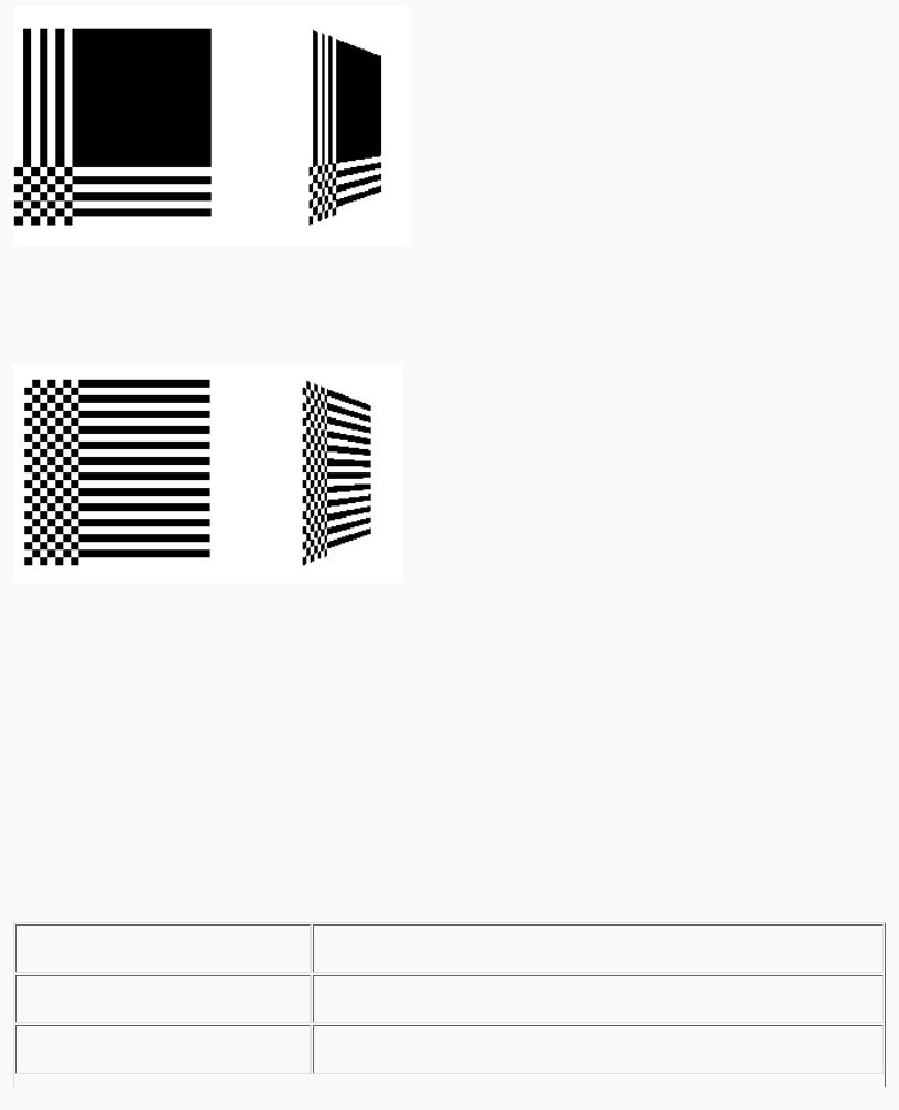
With GL_REPEAT wrapping, the result is as shown in Figure 9-7.
Figure 9-7 : Repeating a Texture
In this case, the texture is repeated in both the s and t directions, since the following calls are made to glTexParameter*():
glTexParameteri(GL_TEXTURE_2D, GL_TEXTURE_WRAP_S, GL_REPEAT); glTexParameteri(GL_TEXTURE_2D, GL_TEXTURE_WRAP_T, GL_REPEAT);
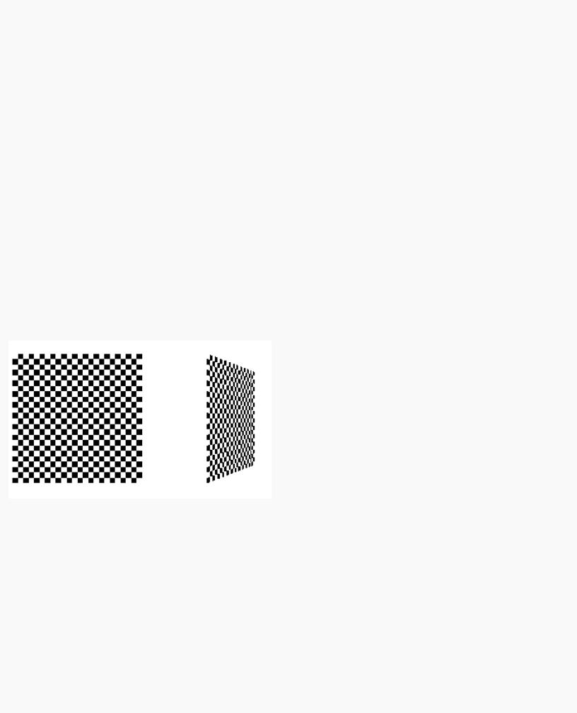
If GL_CLAMP is used instead of GL_REPEAT for each direction, you see something similar to Figure 9-8.
http://heron.cc.ukans.edu/ebt-bin/nph-dweb/dynaw...Generic__BookTextView/17383;cs=fullhtml;pt=14979 (30 of 38) [4/28/2000 9:46:37 PM]
OpenGL Programming Guide (Addison-Wesley Publishing Company)
Figure 9-8 : Clamping a Texture
You can also clamp in one direction and repeat in the other, as shown in Figure 9-9.
Figure 9-9 : Repeating and Clamping a Texture
You've now seen all the possible arguments for glTexParameter*(), which is summarized here.
void glTexParameter{if}(GLenum target, GLenum pname, TYPE param); void glTexParameter{if}v(GLenum target, GLenum pname,
TYPE *param);
Sets various parameters that control how a texture is treated as it's applied to a fragment or stored in a texture object. The target parameter is either GL_TEXTURE_2D or GL_TEXTURE_1D to indicate a twoor one-dimensional texture. The possible values for pname and param are shown in Table 9-4. You can use the vector version of the command to supply an array of values for GL_TEXTURE_BORDER_COLOR, or you can supply individual values for other parameters using the nonvector version. If these values are supplied as integers, they're converted to floating-point according to Table 4-1; they're also clamped to the range [0,1].
Table 9-4 : glTexParameter*() Parameters
http://heron.cc.ukans.edu/ebt-bin/nph-dweb/dynaw...Generic__BookTextView/17383;cs=fullhtml;pt=14979 (31 of 38) [4/28/2000 9:46:37 PM]

OpenGL Programming Guide (Addison-Wesley Publishing Company)
Try This
Figure 9-8 and Figure 9-9 are drawn using GL_NEAREST for the minification and magnification filter. What happens if you change the filter values to GL_LINEAR? Why?
Automatic Texture-Coordinate Generation
You can use texture mapping to make contours on your models or to simulate the reflections from an arbitrary environment on a shiny model. To achieve these effects, let OpenGL automatically generate the texture coordinates for you, rather than explicitly assigning them with glTexCoord*(). To generate texture coordinates automatically, use the command glTexGen().
void glTexGen{ifd}(GLenum coord, GLenum pname, TYPEparam); void glTexGen{ifd}v(GLenum coord, GLenum pname, TYPE *param);
Specifies the functions for automatically generating texture coordinates. The first parameter, coord, must be GL_S, GL_T, GL_R, or GL_Q to indicate whether texture coordinate s, t, r, or q is to be generated. The pname parameter is GL_TEXTURE_GEN_MODE, GL_OBJECT_PLANE, or GL_EYE_PLANE. If it's GL_TEXTURE_GEN_MODE, param is an integer (or, in the vector version of the command, points to an integer) that's either GL_OBJECT_LINEAR, GL_EYE_LINEAR, or GL_SPHERE_MAP. These symbolic constants determine which function is used to generate the texture coordinate. With either of the other possible values for pname, param is a pointer to an array of values (for the vector version) specifying parameters for the texture-generation function.
The different methods of texture-coordinate generation have different uses. Specifying the reference plane in object coordinates is best for when a texture image remains fixed to a moving object. Thus, GL_OBJECT_LINEAR would be used for putting a wood grain on a table top. Specifying the reference plane in eye coordinates (GL_EYE_LINEAR) is best for producing dynamic contour lines on moving objects. GL_EYE_LINEAR may be used by specialists in geosciences, who are drilling for oil or gas. As the drill goes deeper into the ground, the drill may be rendered with different colors to represent the layers of rock at increasing depths. GL_SPHERE_MAP is predominantly used for environment mapping. (See "Environment Mapping.")
Creating Contours
When GL_TEXTURE_GEN_MODE and GL_OBJECT_LINEAR are specified, the generation function is a linear combination of the object coordinates of the vertex (xo,yo,zo,wo):
generated coordinate = p1x0 + p2y0 + p3z0 + p4w0
http://heron.cc.ukans.edu/ebt-bin/nph-dweb/dynaw...Generic__BookTextView/17383;cs=fullhtml;pt=14979 (32 of 38) [4/28/2000 9:46:37 PM]

OpenGL Programming Guide (Addison-Wesley Publishing Company)
The p1, ..., p4 values are supplied as the param argument to glTexGen*v(), with pname set to GL_OBJECT_PLANE. With p1, ..., p4 correctly normalized, this function gives the distance from the vertex to a plane. For example, if p2 = p3 = p4 = 0 and p1 = 1, the function gives the distance between the vertex and the plane x = 0. The distance is positive on one side of the plane, negative on the other, and zero if the vertex lies on the plane.
Initially in Example 9-6, equally spaced contour lines are drawn on a teapot; the lines indicate the distance from the plane x = 0. The coefficients for the plane x = 0 are in this array:
static GLfloat xequalzero[] = {1.0, 0.0, 0.0, 0.0};
Since only one property is being shown (the distance from the plane), a one-dimensional texture map suffices. The texture map is a constant green color, except that at equally spaced intervals it includes a red mark. Since the teapot is sitting on the x-y plane, the contours are all perpendicular to its base. "Plate 18" in Appendix I shows the picture drawn by the program.
In the same example, pressing the `s' key changes the parameters of the reference plane to
static GLfloat slanted[] = {1.0, 1.0, 1.0, 0.0};
the contour stripes are parallel to the plane x + y + z = 0, slicing across the teapot at an angle, as shown in "Plate 18" in Appendix I. To restore the reference plane to its initial value, x = 0, press the `x' key.
Example 9-6 : Automatic Texture-Coordinate Generation: texgen.c
#include <GL/gl.h> #include <GL/glu.h> #include <GL/glut.h> #include <stdlib.h> #include <stdio.h>
#define stripeImageWidth 32
GLubyte stripeImage[4*stripeImageWidth];
static GLuint texName;
void makeStripeImage(void)
{
int j;
for (j = 0; j < stripeImageWidth; j++) { stripeImage[4*j] = (GLubyte) ((j<=4) ? 255 : 0); stripeImage[4*j+1] = (GLubyte) ((j>4) ? 255 : 0); stripeImage[4*j+2] = (GLubyte) 0; stripeImage[4*j+3] = (GLubyte) 255;
}
}
/* planes for texture coordinate generation */ static GLfloat xequalzero[] = {1.0, 0.0, 0.0, 0.0}; static GLfloat slanted[] = {1.0, 1.0, 1.0, 0.0}; static GLfloat *currentCoeff;
static GLenum currentPlane; static GLint currentGenMode;
void init(void)
{
http://heron.cc.ukans.edu/ebt-bin/nph-dweb/dynaw...Generic__BookTextView/17383;cs=fullhtml;pt=14979 (33 of 38) [4/28/2000 9:46:37 PM]

OpenGL Programming Guide (Addison-Wesley Publishing Company)
glClearColor (0.0, 0.0, 0.0, 0.0); glEnable(GL_DEPTH_TEST); glShadeModel(GL_SMOOTH);
makeStripeImage(); glPixelStorei(GL_UNPACK_ALIGNMENT, 1);
glGenTextures(1, &texName); glBindTexture(GL_TEXTURE_1D, texName);
glTexParameteri(GL_TEXTURE_1D, GL_TEXTURE_WRAP_S, GL_REPEAT); glTexParameteri(GL_TEXTURE_1D, GL_TEXTURE_MAG_FILTER,
GL_LINEAR); glTexParameteri(GL_TEXTURE_1D, GL_TEXTURE_MIN_FILTER,
GL_LINEAR);
glTexImage1D(GL_TEXTURE_1D, 0, GL_RGBA, stripeImageWidth, 0, GL_RGBA, GL_UNSIGNED_BYTE, stripeImage);
glTexEnvf(GL_TEXTURE_ENV, GL_TEXTURE_ENV_MODE, GL_MODULATE); currentCoeff = xequalzero;
currentGenMode = GL_OBJECT_LINEAR; currentPlane = GL_OBJECT_PLANE;
glTexGeni(GL_S, GL_TEXTURE_GEN_MODE, currentGenMode); glTexGenfv(GL_S, currentPlane, currentCoeff);
glEnable(GL_TEXTURE_GEN_S); glEnable(GL_TEXTURE_1D); glEnable(GL_CULL_FACE); glEnable(GL_LIGHTING); glEnable(GL_LIGHT0); glEnable(GL_AUTO_NORMAL); glEnable(GL_NORMALIZE); glFrontFace(GL_CW); glCullFace(GL_BACK);
glMaterialf (GL_FRONT, GL_SHININESS, 64.0);
}
void display(void)
{
glClear(GL_COLOR_BUFFER_BIT | GL_DEPTH_BUFFER_BIT);
glPushMatrix (); glRotatef(45.0, 0.0, 0.0, 1.0);
glBindTexture(GL_TEXTURE_1D, texName); glutSolidTeapot(2.0);
glPopMatrix (); glFlush();
}
void reshape(int w, int h)
{
glViewport(0, 0, (GLsizei) w, (GLsizei) h); glMatrixMode(GL_PROJECTION);
http://heron.cc.ukans.edu/ebt-bin/nph-dweb/dynaw...Generic__BookTextView/17383;cs=fullhtml;pt=14979 (34 of 38) [4/28/2000 9:46:37 PM]

OpenGL Programming Guide (Addison-Wesley Publishing Company)
glLoadIdentity(); if (w <= h)
glOrtho (-3.5, 3.5, -3.5*(GLfloat)h/(GLfloat)w, 3.5*(GLfloat)h/(GLfloat)w, -3.5, 3.5);
else
glOrtho (-3.5*(GLfloat)w/(GLfloat)h, 3.5*(GLfloat)w/(GLfloat)h, -3.5, 3.5, -3.5, 3.5);
glMatrixMode(GL_MODELVIEW); glLoadIdentity();
}
void keyboard (unsigned char key, int x, int y)
{
switch (key) { case `e': case `E':
currentGenMode = GL_EYE_LINEAR; currentPlane = GL_EYE_PLANE;
glTexGeni(GL_S, GL_TEXTURE_GEN_MODE, currentGenMode); glTexGenfv(GL_S, currentPlane, currentCoeff); glutPostRedisplay();
break; case `o': case `O':
currentGenMode = GL_OBJECT_LINEAR; currentPlane = GL_OBJECT_PLANE;
glTexGeni(GL_S, GL_TEXTURE_GEN_MODE, currentGenMode); glTexGenfv(GL_S, currentPlane, currentCoeff); glutPostRedisplay();
break; case `s': case `S':
currentCoeff = slanted;
glTexGenfv(GL_S, currentPlane, currentCoeff); glutPostRedisplay();
break; case `x': case `X':
currentCoeff = xequalzero;
glTexGenfv(GL_S, currentPlane, currentCoeff); glutPostRedisplay();
break; case 27:
exit(0);
break;
default:
break;
}
}
int main(int argc, char** argv)
{
http://heron.cc.ukans.edu/ebt-bin/nph-dweb/dynaw...Generic__BookTextView/17383;cs=fullhtml;pt=14979 (35 of 38) [4/28/2000 9:46:37 PM]

OpenGL Programming Guide (Addison-Wesley Publishing Company)
glutInit(&argc, argv);
glutInitDisplayMode (GLUT_SINGLE | GLUT_RGB | GLUT_DEPTH); glutInitWindowSize(256, 256);
glutInitWindowPosition(100, 100); glutCreateWindow (argv[0]);
init (); glutDisplayFunc(display); glutReshapeFunc(reshape); glutKeyboardFunc(keyboard); glutMainLoop();
return 0;
}
You enable texture-coordinate generation for the s coordinate by passing GL_TEXTURE_GEN_S to glEnable(). To generate other coordinates, enable them with GL_TEXTURE_GEN_T, GL_TEXTURE_GEN_R, or GL_TEXTURE_GEN_Q. Use glDisable() with the appropriate constant to disable coordinate generation. Also note the use of GL_REPEAT to cause the contour lines to be repeated across the teapot.
The GL_OBJECT_LINEAR function calculates the texture coordinates in the model's coordinate system. Initially in Example 9-6, the GL_OBJECT_LINEAR function is used, so the contour lines remain perpendicular to the base of the teapot, no matter how the teapot is rotated or viewed. However, if you press the `e' key, the texture generation mode is changed from GL_OBJECT_LINEAR to GL_EYE_LINEAR, and the contour lines are calculated relative to the eye coordinate system. (Pressing the `o' key restores GL_OBJECT_LINEAR as the texture generation mode.) If the reference plane is x = 0, the result is a teapot with red stripes parallel to the y-z plane from the eye's point of view, as shown in "Plate 18" in Appendix I. Mathematically, you are multiplying the vector (p1p2p3p4) by the inverse of the modelview matrix to obtain the values used to calculate the distance to the plane. The texture coordinate is generated with the following function:
generated coordinate = p1'xe + p2'ye + p3'ze + p4'we
where (p1' p2' p3' p4') = (p1p2p3p4)M-1
In this case, (xe, ye, ze, we) are the eye coordinates of the vertex, and p1, ..., p4 are supplied as the param argument to glTexGen*() with pname set to GL_EYE_PLANE. The primed values are calculated only at the time they're specified so this operation isn't as computationally expensive as it looks.
In all these examples, a single texture coordinate is used to generate contours. The s and t texture coordinates can be generated independently, however, to indicate the distances to two different planes. With a properly constructed two-dimensional texture map, the resulting two sets of contours can be viewed simultaneously. For an added level of complexity, you can calculate the s coordinate using GL_OBJECT_LINEAR and the t coordinate using GL_EYE_LINEAR.
Environment Mapping
The goal of environment mapping is to render an object as if it were perfectly reflective, so that the colors on its surface are those reflected to the eye from its surroundings. In other words, if you look at a perfectly polished, perfectly reflective silver object in a room, you see the walls, floor, and other objects in the room reflected off the object. (A classic example of using environment mapping is the evil, morphing cyborg in the film Terminator 2.) The objects whose reflections you see depend on the position of your eye and on the position and surface angles of the silver object. To perform environment mapping, all you have to do is create an appropriate texture map and then have OpenGL generate the texture coordinates for you.
Environment mapping is an approximation based on the assumption that the items in the environment are far away compared to the surfaces of the shiny object - that is, it's a small object in a large room. With this assumption, to find the color of a point on the surface, take the ray from the eye to the surface, and reflect the ray off the surface. The direction
http://heron.cc.ukans.edu/ebt-bin/nph-dweb/dynaw...Generic__BookTextView/17383;cs=fullhtml;pt=14979 (36 of 38) [4/28/2000 9:46:37 PM]
OpenGL Programming Guide (Addison-Wesley Publishing Company)
of the reflected ray completely determines the color to be painted there. Encoding a color for each direction on a flat texture map is equivalent to putting a polished perfect sphere in the middle of the environment and taking a picture of it with a camera that has a lens with a very long focal length placed far away. Mathematically, the lens has an infinite focal length and the camera is infinitely far away. The encoding therefore covers a circular region of the texture map, tangent to the top, bottom, left, and right edges of the map. The texture values outside the circle make no difference, as they are never accessed in environment mapping.
To make a perfectly correct environment texture map, you need to obtain a large silvered sphere, take a photograph of it in some environment with a camera located an infinite distance away and with a lens that has an infinite focal length, and scan in the photograph. To approximate this result, you can use a scanned-in photograph of an environment taken with an extremely wide-angle (or fish-eye) lens. Plate 21 shows a photograph taken with such a lens and the results when that image is used as an environment map.
Once you've created a texture designed for environment mapping, you need to invoke OpenGL's environment-mapping algorithm. This algorithm finds the point on the surface of the sphere with the same tangent surface as the point on the object being rendered, and it paints the object's point with the color visible on the sphere at the corresponding point.
To automatically generate the texture coordinates to support environment mapping, use this code in your program:
glTexGeni(GL_S, GL_TEXTURE_GEN_MODE, GL_SPHERE_MAP); glTexGeni(GL_T, GL_TEXTURE_GEN_MODE, GL_SPHERE_MAP); glEnable(GL_TEXTURE_GEN_S); glEnable(GL_TEXTURE_GEN_T);
The GL_SPHERE_MAP constant creates the proper texture coordinates for the environment mapping. As shown, you need to specify it for both the s and t directions. However, you don't have to specify any parameters for the texture-coordinate generation function.
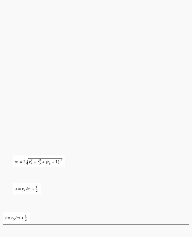
The GL_SPHERE_MAP texture function generates texture coordinates using the following mathematical steps.
1.u is the unit vector pointing from the origin to the vertex (in eye coordinates).
2.n' is the current normal vector, after transformation to eye coordinates.
3.r is the reflection vector, (rxryrz)T, which is calculated by u - 2n'n'Tu.
4.Then an interim value, m, is calculated by
.
1. Finally, the s and t texture coordinates are calculated by
and
.
http://heron.cc.ukans.edu/ebt-bin/nph-dweb/dynaw...Generic__BookTextView/17383;cs=fullhtml;pt=14979 (37 of 38) [4/28/2000 9:46:37 PM]

OpenGL Programming Guide (Addison-Wesley Publishing Company)
Advanced Features
Advanced
This section describes how to manipulate the texture matrix stack and how to use the q coordinate. Both techniques are considered advanced, since you don't need them for many applications of texture mapping.
The Texture Matrix Stack
Just as your model coordinates are transformed by a matrix before being rendered, texture coordinates are multiplied by a 4 × 4 matrix before any texture mapping occurs. By default, the texture matrix is the identity, so the texture coordinates you explicitly assign or those that are automatically generated remain unchanged. By modifying the texture matrix while redrawing an object, however, you can make the texture slide over the surface, rotate around it, stretch and shrink, or any combination of the three. In fact, since the texture matrix is a completely general 4 × 4 matrix, effects such as perspective can be achieved.
When the four texture coordinates (s, t, r, q) are multiplied by the texture matrix, the resulting vector (s' t' r' q') is interpreted as homogeneous texture coordinates. In other words, the texture map is indexed by s'/q' and t'/q' . (Remember that r'/q' is ignored in standard OpenGL, but may be used by implementations that support a 3D texture extension.) The texture matrix is actually the top matrix on a stack, which must have a stack depth of at least two matrices. All the standard matrix-manipulation commands such as glPushMatrix(), glPopMatrix(), glMultMatrix(), and glRotate*() can be applied to the texture matrix. To modify the current texture matrix, you need to set the matrix mode to GL_TEXTURE, as follows:
glMatrixMode(GL_TEXTURE); /* enter texture matrix mode */ glRotated(...);
/* ... other matrix manipulations ... */ glMatrixMode(GL_MODELVIEW); /* back to modelview mode */
The q Coordinate
The mathematics of the q coordinate in a general four-dimensional texture coordinate is as described in the previous section. You can make use of q in cases where more than one projection or perspective transformation is needed. For example, suppose you want to model a spotlight that has some nonuniform pattern - brighter in the center, perhaps, or noncircular, because of flaps or lenses that modify the shape of the beam. You can emulate shining such a light on a flat surface by making a texture map that corresponds to the shape and intensity of a light, and then projecting it on the surface in question using projection transformations. Projecting the cone of light onto surfaces in the scene requires a perspective transformation (q ≠ 1), since the lights might shine on surfaces that aren't perpendicular to them. A second perspective transformation occurs because the viewer sees the scene from a different (but perspective) point of view. (See "Plate 27" in Appendix I for an example, and see "Fast Shadows and Lighting Effects Using Texture Mapping" by Mark Segal, Carl Korobkin, Rolf van Widenfelt, Jim Foran, and Paul Haeberli, SIGGRAPH 1992 Proceedings, (Computer Graphics, 26:2, July 1992, p. 249-252) for more details.)
Another example might arise if the texture map to be applied comes from a photograph that itself was taken in perspective. As with spotlights, the final view depends on the combination of two perspective transformations.
OpenGL Programming Guide (Addison-Wesley Publishing Company)
http://heron.cc.ukans.edu/ebt-bin/nph-dweb/dynaw...Generic__BookTextView/17383;cs=fullhtml;pt=14979 (38 of 38) [4/28/2000 9:46:37 PM]