

The Official Guide to Learning OpenGL, Version 1.1 (Redbook Second Edition)
.pdfOpenGL Programming Guide (Addison-Wesley Publishing Company)
Cheesy Translucency
You can use polygon stippling to simulate a translucent material. This is an especially good solution for systems that don't have blending hardware. Since polygon stipple patterns are 32x32 bits, or 1024 bits, you can go from opaque to transparent in 1023 steps. (In practice, that's many more steps than you need!) For example, if you want a surface that lets through 29 percent of the light, simply make up a stipple pattern where 29 percent (roughly 297) of the pixels in the mask are zero and the rest are one. Even if your surfaces have the same translucency, don't use the same stipple pattern for each one, as they cover exactly the same bits on the screen. Make up a different pattern for each by randomly selecting the appropriate number of pixels to be zero. (See "Displaying Points, Lines, and Polygons" in Chapter 2 for more information about polygon stippling.)
If you don't like the effect with random pixels turned on, you can use regular patterns, but they don't work as well when transparent surfaces are stacked. This is often not a problem because most scenes have relatively few translucent regions that overlap. In a picture of an automobile with translucent windows, your line of sight can go through at most two windows, and usually it's only one.
An Easy Fade Effect
Suppose you have an image that you want to fade gradually to some background color. Define a series of polygon stipple patterns, each of which has more bits turned on so that they represent denser and denser patterns. Then use these patterns repeatedly with a polygon large enough to cover the region over which you want to fade. For example, suppose you want to fade to black in 16 steps. First define 16 different pattern arrays:
GLubyte stips[16][4*32];
Then load them in such a way that each has one-sixteenth of the pixels in a 32 × 32 stipple pattern turned on and that the bitwise OR of all the stipple patterns is all ones. After that, the following code does the trick:
draw_the_picture(); |
|
|
glColor3f(0.0, 0.0, |
0.0); |
/* set color to black */ |
for (i = 0; i < 16; |
i++) { |
|
glPolygonStipple(&stips[i][0]); draw_a_polygon_large_enough_to_cover_the_whole_region();
}
In some OpenGL implementations, you might get better performance by first compiling the stipple patterns into display lists. During your initialization, do something like this:
#define STIP_OFFSET 100 for (i = 0; i < 16; i++) {
glNewList(i+STIP_OFFSET, GL_COMPILE); glPolygonStipple(&stips[i][0]); glEndList();
}
Then, replace this line in the first code fragment
glPolygonStipple(&stips[i][0]);
with
http://heron.cc.ukans.edu/ebt-bin/nph-dweb/dynaweb/SGI_Developer/OpenGL_PG/@Generic__BookTextView/28086;cs=fullhtml;pt=26954 (6 of 22) [4/28/2000 9:49:00 PM]

OpenGL Programming Guide (Addison-Wesley Publishing Company)
glCallList(i);
By compiling the command to set the stipple into a display list, OpenGL might be able to rearrange the data in the stips[ ][ ] array into the hardware-specific form required for maximum stipple-setting speed.
Another application for this technique is if you're drawing a changing picture and want to leave some blur behind that gradually fades out to give some indication of past motion. For example, suppose you're simulating a planetary system and you want to leave trails on the planets to show a recent portion of their path. Again, assuming you want to fade in sixteen steps, set up the stipple patterns as before (using the display-list version, say), and have the main simulation loop look something like this:
current_stipple = 0; |
|
|
while (1) { |
/* loop forever |
*/ |
draw_the_next_frame(); |
|
|
glCallList(current_stipple++); |
|
|
if (current_stipple == 16) current_stipple = 0; |
|
|
glColor3f(0.0, 0.0, 0.0); |
/* set color to |
black */ |
draw_a_polygon_large_enough_to_cover_the_whole_region();
}
Each time through the loop, you clear one-sixteenth of the pixels. Any pixel that hasn't had a planet on it for sixteen frames is certain to be cleared to black. Of course, if your system supports blending in hardware, it's easier to blend in a certain amount of background color with each frame. (See "Displaying Points, Lines, and Polygons" in Chapter 2 for polygon stippling details, Chapter 7 for more information about display lists, and "Blending" in Chapter 6 for information about blending.)
Object Selection Using the Back Buffer
Although the OpenGL selection mechanism (see "Selection" in Chapter 13) is powerful and flexible, it can be cumbersome to use. Often, the situation is simple: Your application draws a scene composed of a substantial number of objects; the user points to an object with the mouse, and the application needs to find the item under the tip of the cursor.
One way to do this requires your application to be running in double-buffer mode. When the user picks an object, the application redraws the entire scene in the back buffer, but instead of using the normal colors for objects, it encodes some kind of object identifier for each object's color. The application then simply reads back the pixel under the cursor, and the value of that pixel encodes the number of the picked object. If many picks are expected for a single, static picture, you can read the entire color buffer once and look in your copy for each attempted pick, rather than read back each pixel individually.
Note that this scheme has an advantage over standard selection in that it picks the object that's in front if multiple objects appear at the same pixel, one behind the other. Since the image with false colors is drawn in the back buffer, the user never sees it; you can redraw the back buffer (or copy it from the front buffer) before swapping the buffers. In color-index mode, the encoding is simple - send the object identifier as the index. In RGBA mode, encode the bits of the identifier into the R, G, and B components.
Be aware that you can run out of identifiers if there are too many objects in the scene. For example, suppose you're running in color-index mode on a system that has 4-bit buffers for color-index information (16 possible different indices) in each of the color buffers, but the scene has thousands of pickable items. To address this issue, the picking can be done in a few passes. To think about this in concrete terms, assume there are fewer than 4096 items, so all the object identifiers can be encoded in 12 bits. In the first pass, draw the scene using indices composed of the 4 high-order bits, then use the second and third passes to draw the middle 4 bits and the 4 low-order bits. After each pass, read the pixel under the cursor, extract the bits, and pack them together at the end to get the object identifier.
http://heron.cc.ukans.edu/ebt-bin/nph-dweb/dynaweb/SGI_Developer/OpenGL_PG/@Generic__BookTextView/28086;cs=fullhtml;pt=26954 (7 of 22) [4/28/2000 9:49:00 PM]

OpenGL Programming Guide (Addison-Wesley Publishing Company)
With this method, the picking takes three times as long, but that's often acceptable. Note that after you have the high-order 4 bits, you eliminate 15/16 of all objects, so you really need to draw only 1/16 of them for the second pass. Similarly, after the second pass, 255 of the 256 possible items have been eliminated. The first pass thus takes about as long as drawing a single frame does, but the second and third passes can be up to 16 and 256 times as fast.
If you're trying to write portable code that works on different systems, break up your object identifiers into chunks that fit on the lowest common denominator of those systems. Also, keep in mind that your system might perform automatic dithering in RGB mode. If this is the case, turn off dithering.
Cheap Image Transformation
If you want to draw a distorted version of a bitmapped image (perhaps simply stretched or rotated, or perhaps drastically modified by some mathematical function), there are many possibilities. You can use the image as a texture map, which allows you to scale, rotate, or otherwise distort the image. If you just want to scale the image, you can use glPixelZoom().
In many cases, you can achieve good results by drawing the image of each pixel as a quadrilateral. Although this scheme doesn't produce images that are as nice as those you would get by applying a sophisticated filtering algorithm (and it might not be sufficient for sophisticated users), it's a lot quicker.
To make the problem more concrete, assume that the original image is m pixels by n pixels, with coordinates chosen from [0, m-1] × [0, n-1]. Let the distortion functions be x(m,n) and y(m,n). For example, if the distortion is simply a zooming by a factor of 3.2, then x(m,n) = 3.2*m and y(m,n) = 3.2*n. The following code draws the distorted image:
glShadeModel(GL_FLAT); glScale(3.2, 3.2, 1.0); for (j=0; j < n; j++) {
glBegin(GL_QUAD_STRIP); for (i=0; i <= m; i++) { glVertex2i(i,j);
glVertex2i(i, j+1); set_color(i,j);
}
glEnd();
}
This code draws each transformed pixel in a solid color equal to that pixel's color and scales the image size by 3.2. The routine set_color() stands for whatever the appropriate OpenGL command is to set the color of the image pixel.
The following is a slightly more complex version that distorts the image using the functions x(i,j) and y(i,j):
glShadeModel(GL_FLAT); for (j=0; j < n; j++) {
glBegin(GL_QUAD_STRIP); for (i=0; i <= m; i++) {
glVertex2i(x(i,j), y(i,j)); glVertex2i(x(i,j+1), y(i,j+1)); set_color(i,j);
}
http://heron.cc.ukans.edu/ebt-bin/nph-dweb/dynaweb/SGI_Developer/OpenGL_PG/@Generic__BookTextView/28086;cs=fullhtml;pt=26954 (8 of 22) [4/28/2000 9:49:00 PM]
OpenGL Programming Guide (Addison-Wesley Publishing Company)
glEnd();
}
An even better distorted image can be drawn with the following code:
glShadeModel(GL_SMOOTH); for (j=0; j < (n-1); j++) {
glBegin(GL_QUAD_STRIP); for (i=0; i < m; i++) { set_color(i,j);
glVertex2i(x(i,j), y(i,j)); set_color(i,j+1); glVertex2i(x(i,j+1), y(i,j+1));
}
glEnd();
}
This code smoothly interpolates color across each quadrilateral. Note that this version produces one fewer quadrilateral in each dimension than do the flat-shaded versions, because the color image is being used to specify colors at the quadrilateral vertices. In addition, you can antialias the polygons with the appropriate blending function (GL_SRC_ALPHA, GL_ONE) to get an even nicer image.
Displaying Layers
In some applications such as semiconductor layout programs, you want to display multiple different layers of materials and indicate where the materials overlap each other.
As a simple example, suppose you have three different substances that can be layered. At any point, eight possible combinations of layers can occur, as shown in Table 14-2.
Table 14-2 : Eight Combinations of Layers
http://heron.cc.ukans.edu/ebt-bin/nph-dweb/dynaweb/SGI_Developer/OpenGL_PG/@Generic__BookTextView/28086;cs=fullhtml;pt=26954 (9 of 22) [4/28/2000 9:49:00 PM]

OpenGL Programming Guide (Addison-Wesley Publishing Company)
You want your program to display eight different colors, depending on the layers present. One arbitrary possibility is shown in the last column of the table. To use this method, use color-index mode and load your color map so that entry 0 is black, entry 1 is red, entry 2 is green, and so on. Note that if the numbers from 0 through 7 are written in binary, the 4 bit is turned on whenever layer 3 appears, the 2 bit whenever layer 2 appears, and the 1 bit whenever layer 1 appears.
To clear the window, set the writemask to 7 (all three layers) and set the clearing color to 0. To draw your image, set the color to 7, and then when you want to draw something in layer n, set the writemask to n. In other types of applications, it might be necessary to selectively erase in a layer, in which case you would use the writemasks just discussed, but set the color to 0 instead of 7. (See "Masking Buffers" in Chapter 10 for more information about writemasks.)
Antialiased Characters
Using the standard technique for drawing characters with glBitmap(), drawing each pixel of a character is an all-or-nothing affair - the pixel is either turned on or not. If you're drawing black characters on a white background, for example, the resulting pixels are either black or white, never a shade of gray. Much smoother, higher-quality images can be achieved if intermediate colors are used when rendering characters (grays, in this example).
Assuming that you're drawing black characters on a white background, imagine a highly magnified picture of the pixels on the screen, with a high-resolution character outline superimposed on it, as shown in the left side of Figure 14-1.
http://heron.cc.ukans.edu/ebt-bin/nph-dweb/dynaweb/SGI_Developer/OpenGL_PG/@Generic__BookTextView/28086;cs=fullhtml;pt=26954 (10 of 22) [4/28/2000 9:49:00 PM]
OpenGL Programming Guide (Addison-Wesley Publishing Company)
Figure 14-1 : Antialiased Characters
Notice that some of the pixels are completely enclosed by the character's outline and should be painted black; some pixels are completely outside the outline and should be painted white; but many pixels should ideally be painted some shade of gray, where the darkness of the gray corresponds to the amount of black in the pixel. If this technique is used, the resulting image on the screen looks better.
If speed and memory usage are of no concern, each character can be drawn as a small image instead of as a bitmap. If you're using RGBA mode, however, this method might require up to 32 bits per pixel of the character to be stored and drawn, instead of the 1 bit per pixel in a standard character. Alternatively, you could use one 8-bit index per pixel and convert these indices to RGBA by table lookup during transfer. In many cases, a compromise is possible that allows you to draw the character with a few gray levels between black and white (say, two or three), and the resulting font description requires only 2 or 3 bits per pixel of storage.
The numbers in the right side of Figure 14-1 indicate the approximate percentage coverage of each pixel: 0 means approximately empty, 1 means approximately one-third coverage, 2 means two-thirds, and 3 means completely covered. If pixels labeled 0 are painted white, pixels labeled 3 are painted black, and pixels labeled 1 and 2 are painted one-third and two-thirds black, respectively, the resulting character looks quite good. Only 2 bits are required to store the numbers 0, 1, 2, and 3, so for 2 bits per pixel, four levels of gray can be saved.
There are basically two methods to implement antialiased characters, depending on whether you're in RGBA or color-index mode.
In RGBA mode, define three different character bitmaps, corresponding to where 1, 2, and 3 appear in Figure 14-1. Set the color to white, and clear for the
http://heron.cc.ukans.edu/ebt-bin/nph-dweb/dynaweb/SGI_Developer/OpenGL_PG/@Generic__BookTextView/28086;cs=fullhtml;pt=26954 (11 of 22) [4/28/2000 9:49:00 PM]
OpenGL Programming Guide (Addison-Wesley Publishing Company)
background. Set the color to one-third gray (RGB = (0.666, 0.666, 0.666)), and draw all the pixels with a 1 in them. Then set RGB = (0.333, 0.333, 0.333), draw with the 2 bitmap, and use RGB = (0.0, 0.0, 0.0) for the 3 bitmap. What you're doing is defining three different fonts and redrawing the string three times, where each pass fills in the bits of the appropriate color densities.
In color-index mode, you can do exactly the same thing, but if you're willing to set up the color map correctly and use writemasks, you can get away with only two bitmaps per character and two passes per string. In the preceding example, set up one bitmap that has a 1 wherever 1 or 3 appears in the character. Set up a second bitmap that has a 1 wherever a 2 or a 3 appears. Load the color map so that 0 gives white, 1 gives light gray, 2 gives dark gray, and 3 gives black. Set the color to 3 (11 in binary) and the writemask to 1, and draw the first bitmap. Then change the writemask to 2, and draw the second. Where 0 appears in Figure 14-1, nothing is drawn in the framebuffer. Where 1, 2, and 3 appear, 1, 2, and 3 appear in the framebuffer.
For this example with only four gray levels, the savings is small - two passes instead of three. If eight gray levels were used instead, the RGBA method would require seven passes, and the color-map masking technique would require only three. With sixteen gray levels, the comparison is fifteen passes to four passes. (See "Masking Buffers" in Chapter 10 for more information about writemasks and "Bitmaps and Fonts" in Chapter 8 for more information about drawing bitmaps.)
Try This
●Can you see how to do RGBA rendering using no more images than the optimized color-index case? Hint: How are RGB fragments normally merged into the color buffer when antialiasing is desired?
Drawing Round Points
Draw near-round, aliased points by enabling point antialiasing, turning blending off, and using an alpha function that passes only fragments with alpha greater than 0.5. (See "Antialiasing" and "Blending" in Chapter 6 for more information about these topics.)
Interpolating Images
Suppose you have a pair of images (where image can mean a bitmap image, or a picture generated using geometry in the usual way), and you want to smoothly blend from one to the other. This can be done easily using the alpha component and appropriate blending operations. Let's say you want to accomplish the blending in ten steps, where image A is shown in frame 0 and image B is shown in frame 9. The obvious approach is to draw image A with alpha equal to (9- &igr; )/9 and image B with an alpha of i/9 in frame i.
The problem with this method is that both images must be drawn in each frame. A faster approach is to draw image A in frame 0. To get frame 1, blend in 1/9 of image B and 8/9 of what's there. For frame 2, blend in 1/8 of image B with 7/8 of what's there. For frame 3, blend in 1/7 of image B with 6/7 of what's there, and so on. For the last step, you're just drawing 1/1 of image B blended with 0/1 of what's left, yielding image B exactly.
To see that this works, if for frame i you have
http://heron.cc.ukans.edu/ebt-bin/nph-dweb/dynaweb/SGI_Developer/OpenGL_PG/@Generic__BookTextView/28086;cs=fullhtml;pt=26954 (12 of 22) [4/28/2000 9:49:00 PM]
OpenGL Programming Guide (Addison-Wesley Publishing Company)
and you blend in B/(9- &igr; ) with (8- &igr; )/(9- &igr; ) of what's there, you get
(See "Blending" in Chapter 6.)
Making Decals
Suppose you're drawing a complex three-dimensional picture using depth-buffering to eliminate the hidden surfaces. Suppose further that one part of your picture is composed of coplanar figures A and B, where B is a sort of decal that should always appear on top of figure A.
Your first approach might be to draw B after you've drawn A, setting the depth-buffering function to replace on greater or equal. Due to the finite precision of the floating-point representations of the vertices, however, round-off error can cause polygon B to be sometimes a bit in front and sometimes a bit behind figure A. Here's one solution to this problem.
1.Disable the depth buffer for writing, and render A.
2.Enable the depth buffer for writing, and render B.
3.Disable the color buffer for writing, and render A again.
4.Enable the color buffer for writing.
Note that during the entire process, the depth-buffer test is enabled. In step 1, A is rendered wherever it should be, but none of the depth-buffer values are changed; thus, in step 2, wherever B appears over A, B is guaranteed to be drawn. Step 3 simply makes sure that all of the depth values under A are updated correctly, but since RGBA writes are disabled, the color pixels are unaffected. Finally, step 4 returns the system to the default state (writing is enabled both in the depth buffer and in the color buffer).
If a stencil buffer is available, the following simpler technique works.
1.Configure the stencil buffer to write one if the depth test passes, and zero otherwise. Render A.
2.Configure the stencil buffer to make no stencil value change, but to render only where stencil values are one. Disable the depth-buffer test and its update. Render B.
With this method, it's not necessary to initialize the contents of the stencil buffer at any time, because the stencil value of all pixels of interest (that is, those rendered by A) are set when A is rendered. Be sure to reenable the depth test and disable the stencil test before additional polygons are drawn. (See "Selecting Color Buffers for Writing and Reading,""Depth Test," and "Stencil Test" in Chapter 10.)
http://heron.cc.ukans.edu/ebt-bin/nph-dweb/dynaweb/SGI_Developer/OpenGL_PG/@Generic__BookTextView/28086;cs=fullhtml;pt=26954 (13 of 22) [4/28/2000 9:49:00 PM]
OpenGL Programming Guide (Addison-Wesley Publishing Company)
Drawing Filled, Concave Polygons Using the Stencil Buffer
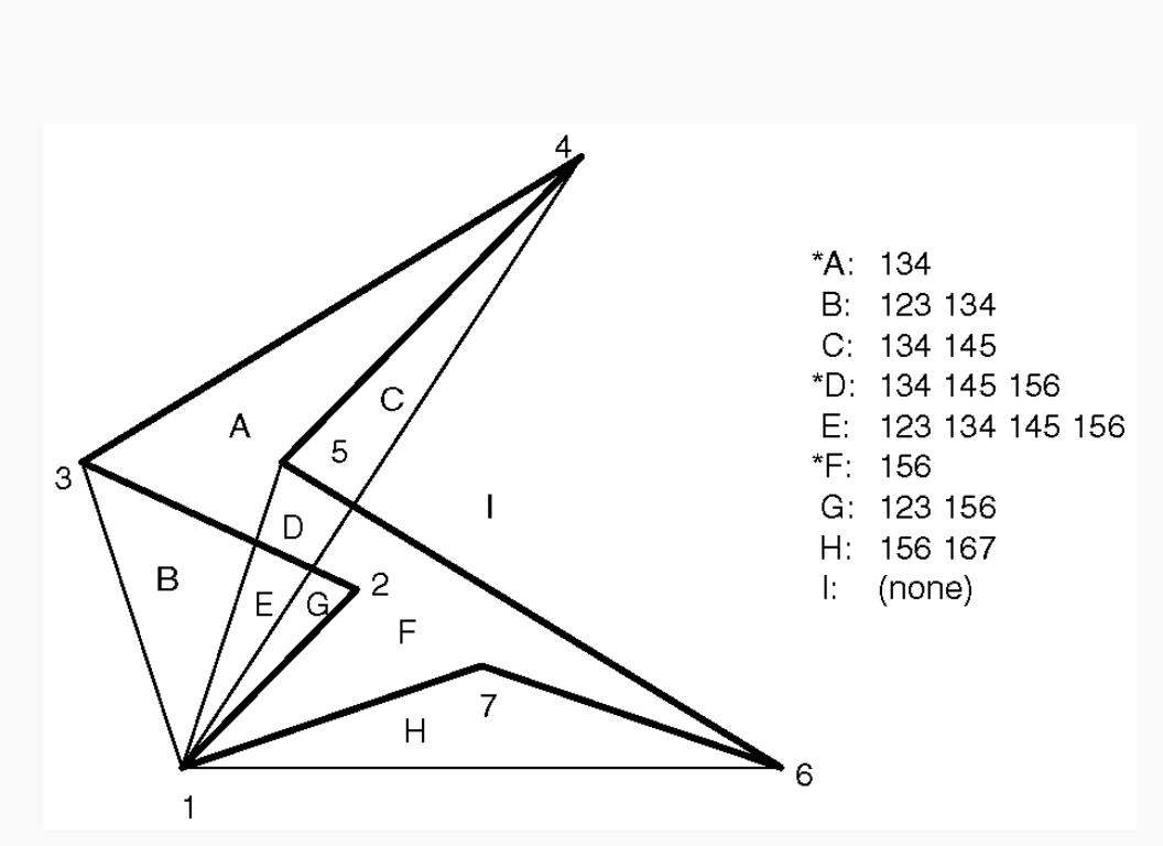
Consider the concave polygon 1234567 shown in Figure 14-2. Imagine that it's drawn as a series of triangles: 123, 134, 145, 156, 167, all of which are shown in the figure. The heavier line represents the original polygon boundary. Drawing all these triangles divides the buffer into nine regions A, B, C, ..., I, where region I is outside all the triangles.
http://heron.cc.ukans.edu/ebt-bin/nph-dweb/dynaweb/SGI_Developer/OpenGL_PG/@Generic__BookTextView/28086;cs=fullhtml;pt=26954 (14 of 22) [4/28/2000 9:49:00 PM]

OpenGL Programming Guide (Addison-Wesley Publishing Company)
Figure 14-2 : Concave Polygon
In the text of the figure, each of the region names is followed by a list of the triangles that cover it. Regions A, D, and F make up the original polygon; note that these three regions are covered by an odd number of triangles. Every other region is covered by an even number of triangles (possibly zero). Thus, to render the inside of the concave polygon, you just need to render regions that are enclosed by an odd number of triangles. This can be done using the stencil buffer, with a two-pass algorithm.
First, clear the stencil buffer and disable writing into the color buffer. Next, draw each of the triangles in turn, using the GL_INVERT function in the stencil buffer. (For best performance, use triangle fans.) This flips the value between zero and a nonzero value every time a triangle is drawn that covers a pixel. After all the triangles are drawn, if a pixel is covered an even number of times, the value in the stencil buffers is zero; otherwise, it's nonzero. Finally, draw a large polygon over the whole region (or redraw the triangles), but allow drawing only where the stencil buffer is nonzero.
Note: There's a slight generalization of the preceding technique, where you don't need to start with a polygon vertex. In the 1234567 example, let P be any point on or off the polygon. Draw the triangles: P12, P23, P34, P45, P56, P67, and P71. Regions covered by an odd number of triangles are inside; other regions are outside. This is a generalization in that if P happens to be one of the polygon's edges, one of the triangles is empty.
This technique can be used to fill both nonsimple polygons (polygons whose edges cross each other) and polygons with holes. The following example illustrates how to handle a complicated polygon with two regions, one four-sided and one five-sided. Assume further that there's a triangular and a four-sided hole (it doesn't matter in which regions the holes lie). Let the two regions be abcd and efghi, and the holes jkl and mnop. Let z be any point on the plane. Draw the following triangles:
zab zbc zcd zda zef zfg zgh zhi zie zjk zkl zlj zmn zno zop zpm
Mark regions covered by an odd number of triangles as in, and those covered by an even number as out. (See "Stencil Test" in Chapter 10 for more information about the stencil buffer.)
Finding Interference Regions
If you're designing a mechanical part made from smaller three-dimensional pieces, you often want to display regions where the pieces overlap. In many cases, such regions indicate design errors where parts of a machine interfere with each other. In the case of moving parts, it can be even more valuable, since a search for interfering regions can be done through a complete mechanical cycle of the design. The method for doing this is complicated, and the description here might be too brief. Complete details can be found in the paper Interactive Inspection of Solids: Cross-sections and Interferences, by Jarek Rossignac, Abe Megahed, and Bengt-Olaf Schneider (SIGGRAPH 1992 Proceedings).
The method is related to the capping algorithm described in "Stencil Test" in Chapter 10. The idea is to pass an arbitrary clipping plane through the objects that you want to test for interference, and then determine when a portion of the clipping plane is inside more than one object at a time. For a static image, the clipping plane can be moved manually to highlight interfering regions; for a dynamic image, it might be easier to use a grid of clipping planes to search for all possible interferences.
Draw each of the objects you want to check and clip them against the clipping plane. Note which pixels are inside the object at that clipping plane using an odd-even count in the stencil buffer, as explained in the preceding section. (For properly formed objects, a point is inside the object if a ray drawn from that point to the eye intersects an odd number of surfaces of the object.) To find interferences, you need to find pixels in the framebuffer where the clipping plane is in the interior of two or more regions at once; in other words, in the intersection of the interiors of any pair of objects.
http://heron.cc.ukans.edu/ebt-bin/nph-dweb/dynaweb/SGI_Developer/OpenGL_PG/@Generic__BookTextView/28086;cs=fullhtml;pt=26954 (15 of 22) [4/28/2000 9:49:00 PM]