

The Official Guide to Learning OpenGL, Version 1.1 (Redbook Second Edition)
.pdfOpenGL Programming Guide (Addison-Wesley Publishing Company)
If multiple objects need to be tested for mutual intersection, store 1 bit every time some intersection appears, and another bit wherever the clipping buffer is inside any of the objects (the union of the objects' interiors). For each new object, determine its interior, find the intersection of that interior with the union of the interiors of the objects so far tested, and keep track of the intersection points. Then add the interior points of the new object to the union of the other objects' interiors.
You can perform the operations described in the preceding paragraph by using different bits in the stencil buffer together with various masking operations. Three bits of stencil buffer are required per pixel - one for the toggling to determine the interior of each object, one for the union of all interiors discovered so far, and one for the regions where interference has occurred so far. To make this discussion more concrete, assume the 1 bit of the stencil buffer is for toggling interior/exterior, the 2 bit is the running union, and the 4 bit is for interferences so far. For each object that you're going to render, clear the 1 bit (using a stencil mask of one and clearing to zero), then toggle the 1 bit by keeping the stencil mask as one and using the GL_INVERT stencil operation.
You can find intersections and unions of the bits in the stencil buffers using the stenciling operations. For example, to make bits in buffer 2 be the union of the bits in buffers 1 and 2, mask the stencil to those 2 bits, and draw something over the entire object with the stencil function set to pass if anything nonzero occurs. This happens if the bits in buffer 1, buffer 2, or both are turned on. If the comparison succeeds, write a 1 in buffer 2. Also, make sure that drawing in the color buffer is disabled. An intersection calculation is similar - set the function to pass only if the value in the two buffers is equal to 3 (bits turned on in both buffers 1 and 2). Write the result into the correct buffer. (See "Stencil Test" in Chapter 10.)
Shadows
Every possible projection of three-dimensional space to three-dimensional space can be achieved with a suitable 4 × 4 invertible matrix and homogeneous coordinates. If the matrix isn't invertible but has rank 3, it projects three-dimensional space onto a two-dimensional plane. Every such possible projection can be achieved with a suitable rank-3 4 × 4 matrix. To find the shadow of an arbitrary object on an arbitrary plane from an arbitrary light source (possibly at infinity), you need to find a matrix representing that projection, multiply it on the matrix stack, and draw the object in the shadow color. Keep in mind that you need to project onto each plane that you're calling the "ground."
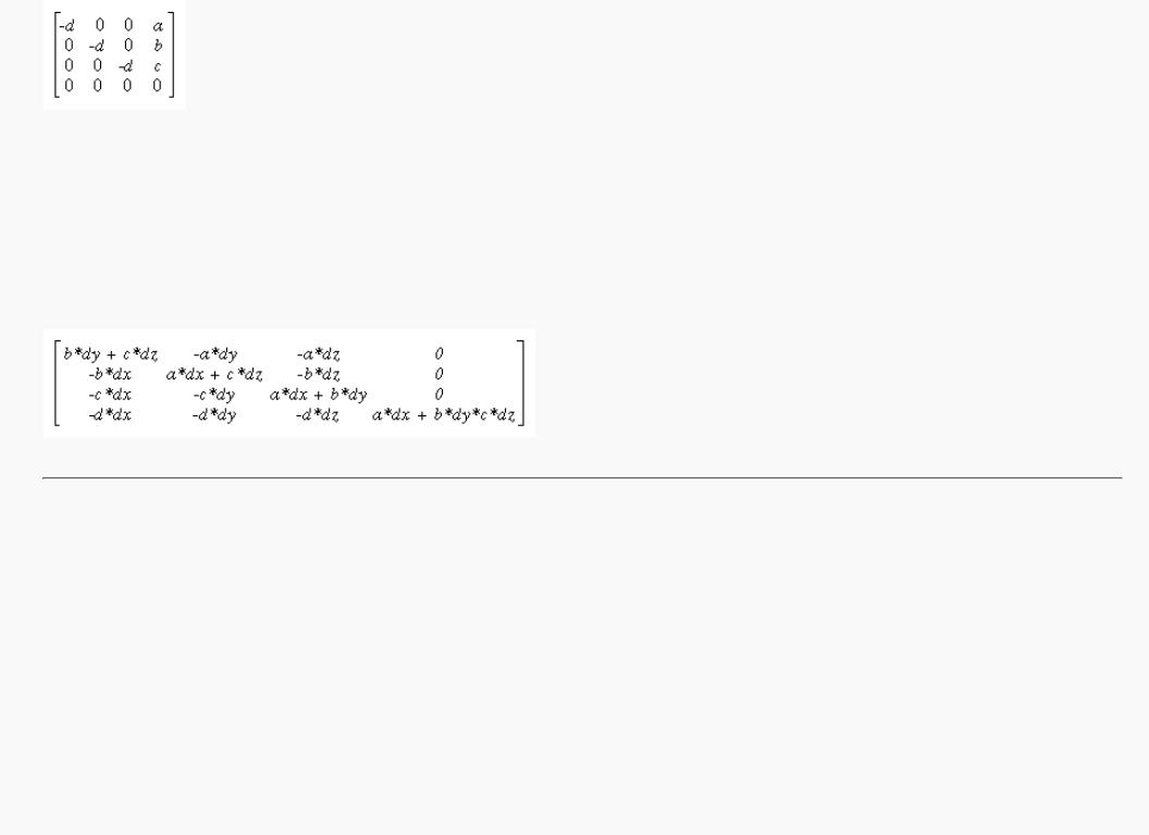
As a simple illustration, assume the light is at the origin, and the equation of the ground plane is ax+by+c+d=0. Given a vertex S=(sx,sy,sz,1), the line from the light through S includes all points &agr; S, where &agr; is an arbitrary real number. The point where this line intersects the plane occurs when
&agr; (a*sz+b*sy+c*sz) + d = 0,
so
&agr; = - &dgr; /(a*sx+b*sy+c*sz).
Plugging this back into the line, we get
- &dgr; ( &sgr; &xgr; , &sgr; &psgr; , &sgr; &zgr; )/( &agr; * &sgr; &xgr; + &bgr; * &sgr; &psgr; + &khgr; * &sgr; &zgr; )
for the point of intersection.
The matrix that maps S to this point for every S is
http://heron.cc.ukans.edu/ebt-bin/nph-dweb/dynaweb/SGI_Developer/OpenGL_PG/@Generic__BookTextView/28086;cs=fullhtml;pt=26954 (16 of 22) [4/28/2000 9:49:00 PM]
OpenGL Programming Guide (Addison-Wesley Publishing Company)
This matrix can be used if you first translate the world so that the light is at the origin.
If the light is from an infinite source, all you have is a point S and a direction D = (dx,dy,dz). Points along the line are given by
S + &agr; D
Proceeding as before, the intersection of this line with the plane is given by
a(sx+ &agr; dx)+b(sy+ &agr; dy)+c(sz+ &agr; dz)+d = 0
Solving for &agr; , plugging that back into the equation for a line, and then determining a projection matrix gives
This matrix works given the plane and an arbitrary direction vector. There's no need to translate anything first. (See Chapter 3 and Appendix F.)
Hidden-Line Removal
If you want to draw a wireframe object with hidden lines removed, one approach is to draw the outlines using lines and then fill the interiors of the polygons making up the surface with polygons having the background color. With depth-buffering enabled, this interior fill covers any outlines that would be obscured by faces closer to the eye. This method would work, except that there's no guarantee that the interior of the object falls entirely inside the polygon's outline; in fact, it might overlap it in various places.
There's an easy, two-pass solution using either polygon offset or the stencil buffer. Polygon offset is usually the preferred technique, since polygon offset is almost always faster than stencil buffer. Both methods are described here, so you can see how both approaches to the problem work.
Hidden-Line Removal with Polygon Offset
To use polygon offset to accomplish hidden-line removal, the object is drawn twice. The highlighted edges are drawn in the foreground color, using filled polygons but with the polygon mode GL_LINE to rasterize it as a wireframe. Then the filled polygons are drawn with the default polygon mode, which fills the interior of the wireframe, and with enough polygon offset to nudge the filled polygons a little farther from the eye. With the polygon offset, the interior recedes just enough that the highlighted edges are drawn without unpleasant visual artifacts.
http://heron.cc.ukans.edu/ebt-bin/nph-dweb/dynaweb/SGI_Developer/OpenGL_PG/@Generic__BookTextView/28086;cs=fullhtml;pt=26954 (17 of 22) [4/28/2000 9:49:00 PM]

OpenGL Programming Guide (Addison-Wesley Publishing Company)
glEnable(GL_DEPTH_TEST); glPolygonMode(GL_FRONT_AND_BACK, GL_LINE); set_color(foreground); draw_object_with_filled_polygons();
glPolygonMode(GL_FRONT_AND_BACK, GL_FILL); glEnable(GL_POLYGON_OFFSET_FILL); glPolygonOffset(1.0, 1.0); set_color(background); draw_object_with_filled_polygons(); glDisable(GL_POLYGON_OFFSET_FILL);
You may need to adjust the amount of offset needed (for wider lines, for example). (See "Polygon Offset" in Chapter 6 for more information.)
Hidden-Line Removal with the Stencil Buffer
Using the stencil buffer for hidden-line removal is a more complicated procedure. For each polygon, you'll need to clear the stencil buffer, and then draw the outline both in the framebuffer and in the stencil buffer. Then when you fill the interior, enable drawing only where the stencil buffer is still clear. To avoid doing an entire stencil-buffer clear for each polygon, an easy way to clear it is simply to draw 0's into the buffer using the same polygon outline. In this way, you need to clear the entire stencil buffer only once.
For example, the following code represents the inner loop you might use to perform such hidden-line removal. Each polygon is outlined in the foreground color, filled with the background color, and then outlined again in the foreground color. The stencil buffer is used to keep the fill color of each polygon from overwriting its outline. To optimize performance, the stencil and color parameters are changed only twice per loop by using the same values both times the polygon outline is drawn.
glEnable(GL_STENCIL_TEST); glEnable(GL_DEPTH_TEST); glClear(GL_STENCIL_BUFFER_BIT); glStencilFunc(GL_ALWAYS, 0, 1); glStencilOp(GL_INVERT, GL_INVERT, GL_INVERT); set_color(foreground);
for (i=0; i < max; i++) { outline_polygon(i); set_color(background); glStencilFunc(GL_EQUAL, 0, 1); glStencilOp(GL_KEEP, GL_KEEP, GL_KEEP); fill_polygon(i); set_color(foreground); glStencilFunc(GL_ALWAYS, 0, 1);
glStencilOp(GL_INVERT, GL_INVERT, GL_INVERT); outline_polygon(i);
}
(See "Stencil Test" in Chapter 10.)
http://heron.cc.ukans.edu/ebt-bin/nph-dweb/dynaweb/SGI_Developer/OpenGL_PG/@Generic__BookTextView/28086;cs=fullhtml;pt=26954 (18 of 22) [4/28/2000 9:49:01 PM]

OpenGL Programming Guide (Addison-Wesley Publishing Company)
Texture-Mapping Applications
Texture mapping is quite powerful, and it can be used in some interesting ways. Here are a few advanced applications of texture mapping.
●Antialiased text - Define a texture map for each character at a relatively high resolution, and then map them onto smaller areas using the filtering provided by texturing. This also makes text appear correctly on surfaces that aren't aligned with the screen, but are tilted and have some perspective distortion.
●Antialiased lines - These can be done like antialiased text: Make the line in the texture several pixels wide, and use the texture filtering to antialias the lines.
●Image scaling and rotation - If you put an image into a texture map and use that texture to map onto a polygon, rotating and scaling the polygon effectively rotates and scales the image.
●Image warping - As in the preceding example, store the image as a texture map, but map it to some spline-defined surface (use evaluators). As you warp the surface, the image follows the warping.
●Projecting images - Put the image in a texture map, and project it as a spotlight, creating a slide projector effect. (See "The q Coordinate" in Chapter 9 for more information about how to model a spotlight using textures.)
(See Chapter 3 for information about rotating and scaling, Chapter 9 for more information about creating textures, and Chapter 12 for details on evaluators.)
Drawing Depth-Buffered Images
For complex static backgrounds, the rendering time for the geometric description of the background can be greater than the time it takes to draw a pixel image of the rendered background. If there's a fixed background and a relatively simple changing foreground, you may want to draw the background and its associated depth-buffered version as an image rather than render it geometrically. The foreground might also consist of items that are time-consuming to render, but whose framebuffer images and depth buffers are available. You can render these items into a depth-buffered environment using a two-pass algorithm.
For example, if you're drawing a model of a molecule made of spheres, you might have an image of a beautifully rendered sphere and its associated depth-buffer values that were calculated using Phong shading or ray-tracing or by using some other scheme that isn't directly available through OpenGL. To draw a complex model, you might be required to draw hundreds of such spheres, which should be depth-buffered together.
To add a depth-buffered image to the scene, first draw the image's depth-buffer values into the depth buffer using glDrawPixels(). Then enable depth-buffering, set the writemask to zero so that no drawing occurs, and enable stenciling such that the stencil buffers get drawn whenever a write to the depth buffer occurs.
Then draw the image into the color buffer, masked by the stencil buffer you've just written so that writing occurs only when there's a 1 in the stencil buffer. During this write, set the stenciling function to zero out the stencil buffer so that it's automatically cleared when it's time to add the next image to the scene. If the objects are to be moved nearer to or farther from the viewer, you need to use an orthographic projection; in these cases, you use GL_DEPTH_BIAS with glPixelTransfer*() to move the depth image. (See "Coordinate System Survival Kit" in Chapter 2, "Depth Test" and "Stencil Test" in Chapter 10, and Chapter 8 for details on glDrawPixels() and glPixelTransfer*().)
http://heron.cc.ukans.edu/ebt-bin/nph-dweb/dynaweb/SGI_Developer/OpenGL_PG/@Generic__BookTextView/28086;cs=fullhtml;pt=26954 (19 of 22) [4/28/2000 9:49:01 PM]
OpenGL Programming Guide (Addison-Wesley Publishing Company)
Dirichlet Domains
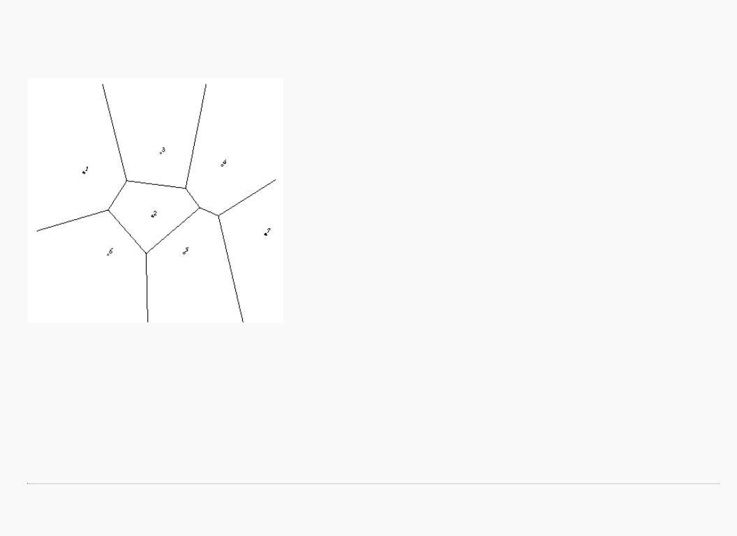
Given a set S of points on a plane, the Dirichlet domain or Voronoi polygon of one of the points is the set of all points in the plane closer to that point than to any other point in the set S. These points provide the solution to many problems in computational geometry. Figure 14-3 shows outlines of the Dirichlet domains for a set of points.
Figure 14-3 : Dirichlet Domains
If you draw a depth-buffered cone with its apex at the point in a different color than each of the points in S, the Dirichlet domain for each point is drawn in that color. The easiest way to do this is to precompute a cone's depth in an image and use the image as the depth-buffer values as described in the preceding section. You don't need an image to draw in the framebuffer as in the case of shaded spheres, however. While you're drawing into the depth buffer, use the stencil buffer to record the pixels where drawing should occur by first clearing it and then writing nonzero values wherever the depth test succeeds. To draw the Dirichlet region, draw a polygon over the entire window, but enable drawing only where the stencil buffers are nonzero.
You can do this perhaps more easily by rendering cones of uniform color with a simple depth buffer, but a good cone might require thousands of polygons. The technique described in this section can render much higher-quality cones much more quickly. (See "A Hidden-Surface Removal Survival Kit" in Chapter 5 and "Depth Test" in Chapter 10.)
http://heron.cc.ukans.edu/ebt-bin/nph-dweb/dynaweb/SGI_Developer/OpenGL_PG/@Generic__BookTextView/28086;cs=fullhtml;pt=26954 (20 of 22) [4/28/2000 9:49:01 PM]
OpenGL Programming Guide (Addison-Wesley Publishing Company)
Life in the Stencil Buffer
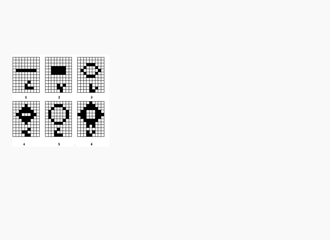
The Game of Life, invented by John Conway, is played on a rectangular grid where each grid location is "alive" or "dead." To calculate the next generation from the current one, count the number of live neighbors for each grid location (the eight adjacent grid locations are neighbors). A grid location is alive in generation n+1 if it was alive in generation n and has exactly two or three live neighbors, or if it was dead in generation n and has exactly three live neighbors. In all other cases, it is dead in generation n+1. This game generates some incredibly interesting patterns given different initial configurations. (See Martin Gardner, "Mathematical Games," Scientific American, vol. 223, no. 4, October 1970, p. 120-123.) Figure 14-4 shows six generations from a game.
.
Figure 14-4 : Six Generations from the Game of Life
One way to create this game using OpenGL is to use a multipass algorithm. Keep the data in the color buffer, one pixel for each grid point. Assume that black (all zeros) is the background color, and the color of a live pixel is nonzero. Initialize by clearing the depth and stencil buffers to zero, set the depth-buffer writemask to zero, and set the depth comparison function so that it passes on not-equal. To iterate, read the image off the screen, enable drawing into the depth buffer, and set the stencil function so that it increments whenever a depth comparison succeeds but leaves the stencil buffer unchanged otherwise. Disable drawing into the color buffer.
Next, draw the image eight times, offset one pixel in each vertical, horizontal, and diagonal direction. When you're done, the stencil buffer contains a count of the number of live neighbors for each pixel. Enable drawing to the color buffer, set the color to the color for live cells, and set the stencil function to draw only if the value in the stencil buffer is 3 (three live neighbors). In addition, if this drawing occurs, decrement the value in the stencil buffer. Then draw a rectangle covering the image; this paints each cell that has exactly three live neighbors with the "alive" color.
At this point, the stencil buffers contain 0, 1, 2, 4, 5, 6, 7, 8, and the values under the 2's are correct. The values under 0, 1, 4, 5, 6, 7, and 8 must be cleared to the "dead" color. Set the stencil function to draw whenever the value is not 2, and to zero the stencil values in all cases. Then draw a large polygon of the "dead"
http://heron.cc.ukans.edu/ebt-bin/nph-dweb/dynaweb/SGI_Developer/OpenGL_PG/@Generic__BookTextView/28086;cs=fullhtml;pt=26954 (21 of 22) [4/28/2000 9:49:01 PM]

OpenGL Programming Guide (Addison-Wesley Publishing Company)
color across the entire image. You're done.
For a usable demonstration program, you might want to zoom the grid up to a size larger than a single pixel; it's hard to see detailed patterns with a single pixel per grid point. (See "Coordinate System Survival Kit" in Chapter 2, and "Depth Test" and "Stencil Test" in Chapter 10.)
Alternative Uses for glDrawPixels() and glCopyPixels()
You might think of glDrawPixels() as a way to draw a rectangular region of pixels to the screen. Although this is often what it's used for, some other interesting uses are outlined here.
●Video - Even if your machine doesn't have special video hardware, you can display short movie clips by repeatedly drawing frames with glDrawPixels() in the same region of the back buffer and then swapping the buffers. The size of the frames you can display with reasonable performance using this method depends on your hardware's drawing speed, so you might be limited to 100 × 100 pixel movies (or smaller) if you want smooth fake video.
●Airbrush - In a paint program, your airbrush (or paintbrush) shape can be simulated using alpha values. The color of the paint is represented as the color values. To paint with a circular brush in blue, repeatedly draw a blue square with glDrawPixels() where the alpha values are largest in the center and taper to zero at the edges of a circle centered in the square. Draw using a blending function that uses alpha of the incoming color and (1-alpha) of the color already at the pixel. If the alpha values in the brush are all much less than one, you have to paint over an area repeatedly to get a solid color. If the alpha values are near one, each brush stroke pretty much obliterates the colors underneath.
●Filtered Zooms - If you zoom a pixel image by a nonintegral amount, OpenGL effectively uses a box filter, which can lead to rather severe aliasing effects. To improve the filtering, jitter the resulting image by amounts less than a pixel and redraw it multiple times, using alpha blending to average the resulting pixels. The result is a filtered zoom.
●Transposing Images - You can swap same-size images in place with glCopyPixels() using the XOR operation. With this method, you can avoid having to read the images back into processor memory. If A and B represent the two images, the operation looks like this:
1.A = A XOR B
2.B = A XOR B
3.A = A XOR B
OpenGL Programming Guide (Addison-Wesley Publishing Company)
http://heron.cc.ukans.edu/ebt-bin/nph-dweb/dynaweb/SGI_Developer/OpenGL_PG/@Generic__BookTextView/28086;cs=fullhtml;pt=26954 (22 of 22) [4/28/2000 9:49:01 PM]

OpenGL Programming Guide (Addison-Wesley Publishing Company)
OpenGL Programming Guide (Addison-Wesley Publishing Company)
Appendix A
Order of Operations
This book describes all the operations performed between when vertices are initially specified and fragments are finally written into the framebuffer. The chapters of this book are arranged in an order that facilitates learning rather than in the exact order in which these operations are actually performed. Sometimes the exact order of operations doesn't matter - for example, surfaces can be converted to polygons and then transformed, or transformed first and then converted to polygons, with identical results - and different implementations of OpenGL might do things differently.
This appendix describes a possible order; any implementation is required to give equivalent results. If you want more details than are presented here, see the OpenGL Reference Manual.
This appendix has the following major sections:
●"Overview"
●"Geometric Operations"
●"Pixel Operations"
●"Fragment Operations"
●"Odds and Ends"
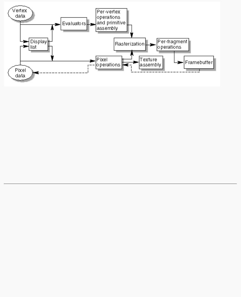
Overview
This section gives an overview of the order of operations, as shown in Figure A-1. Geometric data (vertices, lines, and polygons) follows the path through the row of boxes that include evaluators and per-vertex operations, while pixel data (pixels, images, and bitmaps) is treated differently for part of the process. Both types of data undergo the rasterization and per-fragment operations before the final pixel data is written into the framebuffer.
http://heron.cc.ukans.edu/ebt-bin/nph-dweb/dynaw...Generic__BookTextView/29478;cs=fullhtml;pt=28086 (1 of 4) [4/28/2000 9:49:28 PM]
OpenGL Programming Guide (Addison-Wesley Publishing Company)
Figure A-1 : Order of Operations
All data, whether it describes geometry or pixels, can be saved in a display list or processed immediately. When a display list is executed, the data is sent from the display list just as if it were sent by the application.
All geometric primitives are eventually described by vertices. If evaluators are used, that data is converted to vertices and treated as vertices from then on. Vertex data may also be stored in and used from specialized vertex arrays. Per-vertex calculations are performed on each vertex, followed by rasterization to fragments. For pixel data, pixel operations are performed, and the results are either stored in the texture memory, used for polygon stippling, or rasterized to fragments.
Finally, the fragments are subjected to a series of per-fragment operations, after which the final pixel values are drawn into the framebuffer.
Geometric Operations
Geometric data, whether it comes from a display list, an evaluator, the vertices of a rectangle, or as raw data, consists of a set of vertices and the type of primitive it describes (a vertex, line, or polygon). Vertex data includes not only the (x, y, z, w) coordinates, but also a normal vector, texture coordinates, a RGBA color, a color index, material properties, and edge-flag data. All these elements except the vertex's coordinates can be specified in any order, and default values exist as well. As soon as the vertex command glVertex*() is issued, the components are padded, if necessary, to four dimensions (using z = 0 and w = 1), and the current values of all the elements are associated with the vertex. The complete set of vertex data is then processed. (If vertex arrays are used, vertex data may be batch processed and processed vertices may be reused.)
http://heron.cc.ukans.edu/ebt-bin/nph-dweb/dynaw...Generic__BookTextView/29478;cs=fullhtml;pt=28086 (2 of 4) [4/28/2000 9:49:28 PM]

OpenGL Programming Guide (Addison-Wesley Publishing Company)
Per-Vertex Operations
In the per-vertex operations stage of processing, each vertex's spatial coordinates are transformed by the modelview matrix, while the normal vector is transformed by that matrix's inverse transpose and renormalized if specified. If automatic texture generation is enabled, new texture coordinates are generated from the transformed vertex coordinates, and they replace the vertex's old texture coordinates. The texture coordinates are then transformed by the current texture matrix and passed on to the primitive assembly step.
Meanwhile, the lighting calculations, if enabled, are performed using the transformed vertex and normal vector coordinates, and the current material, lights, and lighting model. These calculations generate new colors or indices that are clamped or masked to the appropriate range and passed on to the primitive assembly step.
Primitive Assembly
Primitive assembly differs, depending on whether the primitive is a point, a line, or a polygon. If flat shading is enabled, the colors or indices of all the vertices in a line or polygon are set to the same value. If special clipping planes are defined and enabled, they're used to clip primitives of all three types. (The clipping-plane equations are transformed by the inverse transpose of the modelview matrix when they're specified.) Point clipping simply passes or rejects vertices; line or polygon clipping can add additional vertices depending on how the line or polygon is clipped. After this clipping, the spatial coordinates of each vertex are transformed by the projection matrix, and the results are clipped against the standard viewing planes x = ± &ohgr; , y = ± &ohgr; , and z = ± &ohgr; .
If selection is enabled, any primitive not eliminated by clipping generates a selection-hit report, and no further processing is performed. Without selection, perspective division by w occurs and the viewport and depth-range operations are applied. Also, if the primitive is a polygon, it's then subjected to a culling test (if culling is enabled). A polygon might convert to vertices or lines, depending on the polygon mode.
Finally, points, lines, and polygons are rasterized to fragments, taking into account polygon or line stipples, line width, and point size. Rasterization involves determining which squares of an integer grid in window coordinates are occupied by the primitive. If antialiasing is enabled, coverage (the portion of the square that is occupied by the primitive) is also computed. Color and depth values are also assigned to each such square. If polygon offset is enabled, depth values are slightly modified by a calculated offset value.
Pixel Operations
Pixels from host memory are first unpacked into the proper number of components. The OpenGL unpacking facility handles a number of different formats. Next, the data is scaled, biased, and processed using a pixel map. The results are clamped to an appropriate range depending on the data type and then either written in the texture memory for use in texture mapping or rasterized to fragments.
If pixel data is read from the framebuffer, pixel-transfer operations (scale, bias, mapping, and clamping) are performed. The results are packed into an appropriate format and then returned to processor memory.
http://heron.cc.ukans.edu/ebt-bin/nph-dweb/dynaw...Generic__BookTextView/29478;cs=fullhtml;pt=28086 (3 of 4) [4/28/2000 9:49:28 PM]