

Creating a geometry shader
There’s not much to explain, geometry shaders are created and activated in exactly the same way as other types of shaders. Let’s add a geometry shader to our 4 point sample that doesn’t do anything yet.
const char* geometryShaderSrc = R"glsl( layout(points) in;
layout(points, max_vertices = 1) out;
void main()
{
gl_Position = gl_in[0].gl_Position; EmitVertex();
EndPrimitive();
}
)glsl";
This geometry shader should be fairly straightforward. For each input point, it generates one equivalent output point. This is the minimum amount of code necessary to still display the points on the screen.
With the helper function, creating a geometry shader is easy:
GLuint geometryShader = createShader(GL_GEOMETRY_SHADER, geometryShaderSrc);
There’s nothing special about attaching it to the shader program either: glAttachShader(shaderProgram, geometryShader);
When you run the program now, it should still display the points as before. You can verify that the geometry shader is now doing its work by removing the code from its main function. You’ll see that no points are being drawn anymore, because none are being generated!
Now, try replacing the geometry shader code with the line strip generating code from the previous section:
layout(points) in;
layout(line_strip, max_vertices = 2) out;
void main()
{
gl_Position = gl_in[0].gl_Position + vec4(-0.1, 0.0, 0.0, 0.0); EmitVertex();
gl_Position = gl_in[0].gl_Position + vec4(0.1, 0.0, 0.0, 0.0); EmitVertex();
EndPrimitive();
89
}
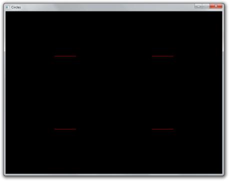
Even though we’ve made no changes to our draw call, the GPU is suddenly drawing tiny lines instead of points!
Figure 47:
Try experimenting a bit to get a feel for it. For example, try outputting rectangles by using triangle_strip.
Geometry shaders and vertex attributes
Let’s add some variation to the lines that are being drawn by allowing each of them to have a unique color. By adding a color input variable to the vertex shader, we can specify a color per vertex and thus per generated line.
in vec2 pos; in vec3 color;
out vec3 vColor; // Output to geometry (or fragment) shader
void main()
90
{
gl_Position = vec4(pos, 0.0, 1.0); vColor = color;
}
Update the vertex specification in the program code:
GLint posAttrib = glGetAttribLocation(shaderProgram, "pos"); glEnableVertexAttribArray(posAttrib);
glVertexAttribPointer(posAttrib, 2, GL_FLOAT, GL_FALSE, 5 * sizeof(float), 0);
GLint colAttrib = glGetAttribLocation(shaderProgram, "color"); glEnableVertexAttribArray(colAttrib); glVertexAttribPointer(colAttrib, 3, GL_FLOAT, GL_FALSE,
5 * sizeof(float), (void*) (2 * sizeof(float)));
And update the point data to include an RGB color per point:
float points[] = {
-0.45f, 0.45f, 1.0f, 0.0f, 0.0f, // Red point 0.45f, 0.45f, 0.0f, 1.0f, 0.0f, // Green point 0.45f, -0.45f, 0.0f, 0.0f, 1.0f, // Blue point -0.45f, -0.45f, 1.0f, 1.0f, 0.0f, // Yellow point
};
Because the vertex shader is now not followed by a fragment shader, but a geometry shader, we have to handle the vColor variable as input there.
layout(points) in;
layout(line_strip, max_vertices = 2) out;
in vec3 vColor[]; // Output from vertex shader for each vertex
out vec3 fColor; // Output to fragment shader
void main()
{
...
You can see that it is very similar to how inputs are handled in the fragment shader. The only di erence is that inputs must be arrays now, because the geometry shader can receive primitives with multiple vertices as input, each with its own attribute values.
Because the color needs to be passed further down to the fragment shader, we add it as output of the geometry shader. We can now assign values to it, just like we did earlier with gl_Position.
void main()
{
91
fColor = vColor[0]; // Point has only one vertex
gl_Position = gl_in[0].gl_Position + vec4(-0.1, 0.1, 0.0, 0.0); EmitVertex();
gl_Position = gl_in[0].gl_Position + vec4(0.1, 0.1, 0.0, 0.0); EmitVertex();
EndPrimitive();
}
Whenever EmitVertex is called now, a vertex is emitted with the current value of fColor as color attribute. We can now access that attribute in the fragment shader:
in vec3 fColor;
out vec4 outColor;
void main()
{
outColor = vec4(fColor, 1.0);
}
So, when you specify an attribute for a vertex, it is first passed to the vertex shader as input. The vertex shader can then choose to output it to the geometry shader. And then the geometry shader can choose to further output it to the fragment shader.
However, this demo is not very interesting. We could easily replicate this behaviour by creating a vertex bu er with a single line and issuing a couple of draw calls with di erent colors and positions set with uniform variables.
Dynamically generating geometry
The real power of geometry shader lies in the ability to generate a varying amount of primitives, so let’s create a demo that properly abuses this ability.
Let’s say you’re making a game where the world consists of circles. You could draw a single model of a circle and repeatedly draw it, but this approach is not ideal. If you’re too close, these “circles” will look like ugly polygons and if you’re too far away, your graphics card is wasting performance on rendering complexity you can’t even see.
We can do better with geometry shaders! We can write a shader that generates the appropriate resolution circle based on run-time conditions. Let’s first modify the geometry shader to draw a 10-sided polygon at each point. If you remember your trigonometry, it should be a piece of cake:
92
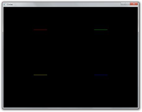
Figure 48:
93
layout(points) in;
layout(line_strip, max_vertices = 11) out;
in vec3 vColor[]; out vec3 fColor;
const float PI = 3.1415926;
void main()
{
fColor = vColor[0];
for (int i = 0; i <= 10; i++) {
//Angle between each side in radians float ang = PI * 2.0 / 10.0 * i;
//Offset from center of point (0.3 to accomodate for aspect ratio) vec4 offset = vec4(cos(ang) * 0.3, -sin(ang) * 0.4, 0.0, 0.0); gl_Position = gl_in[0].gl_Position + offset;
EmitVertex();
}
EndPrimitive();
}
The first point is repeated to close the line loop, which is why 11 vertices are drawn. The result is as expected:
It is now trivial to add a vertex attribute to control the amount of sides. Add the new attribute to the data and to the specification:
float points[] = {
// Coordinates Color Sides -0.45f, 0.45f, 1.0f, 0.0f, 0.0f, 4.0f, 0.45f, 0.45f, 0.0f, 1.0f, 0.0f, 8.0f, 0.45f, -0.45f, 0.0f, 0.0f, 1.0f, 16.0f, -0.45f, -0.45f, 1.0f, 1.0f, 0.0f, 32.0f
};
...
// Specify layout of point data
GLint posAttrib = glGetAttribLocation(shaderProgram, "pos"); glEnableVertexAttribArray(posAttrib); glVertexAttribPointer(posAttrib, 2, GL_FLOAT, GL_FALSE,
6 * sizeof(float), 0);
94
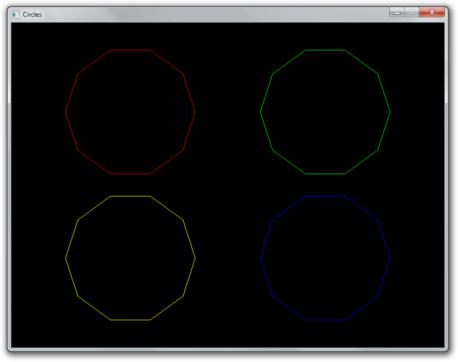
Figure 49:
95
GLint colAttrib = glGetAttribLocation(shaderProgram, "color"); glEnableVertexAttribArray(colAttrib); glVertexAttribPointer(colAttrib, 3, GL_FLOAT, GL_FALSE,
6 * sizeof(float), (void*) (2 * sizeof(float)));
GLint sidesAttrib = glGetAttribLocation(shaderProgram, "sides"); glEnableVertexAttribArray(sidesAttrib); glVertexAttribPointer(sidesAttrib, 1, GL_FLOAT, GL_FALSE,
6 * sizeof(float), (void*) (5 * sizeof(float)));
Alter the vertex shader to pass the value to the geometry shader:
in vec2 pos; in vec3 color; in float sides;
out vec3 vColor; out float vSides;
void main()
{
gl_Position = vec4(pos, 0.0, 1.0); vColor = color;
vSides = sides;
}
And use the variable in the geometry shader instead of the magic number of sides 10.0. It’s also necessary to set an appropriate max_vertices value for our input, otherwise the circles with more vertices will be cut o .
layout(line_strip, max_vertices = 64) out;
...
in float vSides[];
...
// Safe, floats can represent small integers exactly for (int i = 0; i <= vSides[0]; i++) {
// Angle between each side in radians float ang = PI * 2.0 / vSides[0] * i;
...
You can now create a circles with any amount of sides you desire by simply adding more points!
96
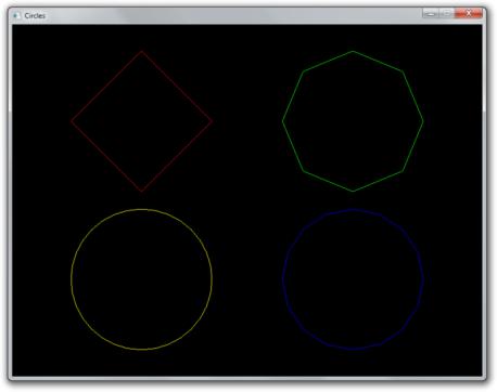
Figure 50:
97