

Putting it all together
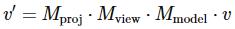
To sum it all up, the final transformation of a vertex is the product of the model, view and projection matrices.
Figure 32:
This operation is typically performed in the vertex shader and assigned to the gl_Position return value in clipping coordinates. OpenGL will perform the perspective division and transformation into window coordinates. It is important to be aware of these steps, because you’ll have to do them yourself when working with techniques like shadow mapping.
Using transformations for 3D
Now that you know three important transformations, it is time to implement these in code to create an actual 3D scene. You can use any of the programs developed in the last two chapters as a base, but I’ll use the texture blending sample from the end of the last chapter here.
To introduce matrices in the code, we can make use of the GLM (OpenGL Math) library. This library comes with vector and matrix classes and will handle all the math e ciently without ever having to worry about it. It is a header-only library, which means you don’t have to link with anything.
To use it, add the GLM root directory to your include path and include these three headers:
#include <glm/glm.hpp>
#include <glm/gtc/matrix_transform.hpp> #include <glm/gtc/type_ptr.hpp>
The second header includes functions to ease the calculation of the view and projection matrices. The third header adds functionality for converting a matrix object into a float array for usage in OpenGL.
A simple transformation
Before diving straight into 3D, let’s first try a simple 2D rotation.
glm::mat4 trans;
trans = glm::rotate(trans, glm::radians(180.0f), glm::vec3(0.0f, 0.0f, 1.0f));
55
The first line creates a new 4-by-4 matrix, which is the identity matrix by default. The glm::rotate function multiplies this matrix by a rotation transformation of 180 degrees around the Z axis. Remember that since the screen lies in the XY plane, the Z axis is the axis you want to rotate points around.
To see if it works, let’s try to rotate a vector with this transformation:
glm::vec4 result = trans * glm::vec4(1.0f, 0.0f, 0.0f, 1.0f); printf("%f, %f, %f\n", result.x, result.y, result.z);
As expected, the output is (-1,0,0). A counter-clockwise rotation of 180 degrees of a vector pointing to the right results in a vector pointing to the left. Note that the rotation would be clockwise if an axis (0,0,-1) was used.
The next step is to perform this transformation in the vertex shader to rotate every drawn vertex. GLSL has a special mat4 type to hold matrices and we can use that to upload the transformation to the GPU as uniform.
GLint uniTrans = glGetUniformLocation(shaderProgram, "trans"); glUniformMatrix4fv(uniTrans, 1, GL_FALSE, glm::value_ptr(trans));
The second parameter of the glUniformMatrix4fv function specifies how many matrices are to be uploaded, because you can have arrays of matrices in GLSL. The third parameter specifies whether the specified matrix should be transposed before usage. This is related to the way matrices are stored as float arrays in memory; you don’t have to worry about it. The last parameter specifies the matrix to upload, where the glm::value_ptr function converts the matrix class into an array of 16 (4x4) floats.
All that remains is updating the vertex shader to include this uniform and use it to transform each vertex:
#version 150
in vec2 position; in vec3 color; in vec2 texcoord;
out vec3 Color; out vec2 Texcoord;
uniform mat4 trans;
void main()
{
Color = color; Texcoord = texcoord;
gl_Position = trans * vec4(position, 0.0, 1.0);
}
56
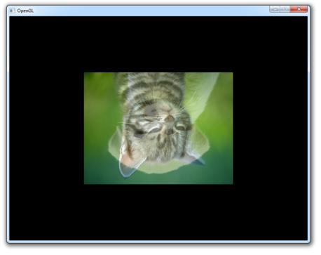
The primitives in your scene will now be upside down.
Figure 33:
To spice things up a bit, you could change the rotation with time: auto t_start = std::chrono::high_resolution_clock::now();
...
// Calculate transformation
auto t_now = std::chrono::high_resolution_clock::now();
float time = std::chrono::duration_cast<std::chrono::duration<float>>(t_now - t_start).coun
glm::mat4 trans; trans = glm::rotate(
trans,
time * glm::radians(180.0f), glm::vec3(0.0f, 0.0f, 1.0f)
);
glUniformMatrix4fv(uniTrans, 1, GL_FALSE, glm::value_ptr(trans));
// Draw a rectangle from the 2 triangles using 6 indices
57
glDrawElements(GL_TRIANGLES, 6, GL_UNSIGNED_INT, 0);
...
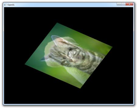
This will result in something like this:
Figure 34:
You can find the full code here if you have any issues.
Going 3D
The rotation above can be considered the model transformation, because it transforms the vertices in object space to world space using the rotation of the object.
glm::mat4 view = glm::lookAt( glm::vec3(1.2f, 1.2f, 1.2f), glm::vec3(0.0f, 0.0f, 0.0f), glm::vec3(0.0f, 0.0f, 1.0f)
);
GLint uniView = glGetUniformLocation(shaderProgram, "view");
58
glUniformMatrix4fv(uniView, 1, GL_FALSE, glm::value_ptr(view));
To create the view transformation, GLM o ers the useful glm::lookAt function that simulates a moving camera. The first parameter specifies the position of the camera, the second the point to be centered on-screen and the third the up axis. Here up is defined as the Z axis, which implies that the XY plane is the “ground”.
glm::mat4 proj = glm::perspective(glm::radians(45.0f), 800.0f / 600.0f, 1.0f, 10.0f); GLint uniProj = glGetUniformLocation(shaderProgram, "proj"); glUniformMatrix4fv(uniProj, 1, GL_FALSE, glm::value_ptr(proj));
Similarly, GLM comes with the glm::perspective function to create a perspective projection matrix. The first parameter is the vertical field-of-view, the second parameter the aspect ratio of the screen and the last two parameters are the near and far planes.
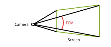
Field-of-view The field-of-view defines the angle between the top and bottom of the 2D surface on which the world will be projected. Zooming in games is often accomplished by decreasing this angle as opposed to moving the camera closer, because it more closely resembles real life.
Figure 35:
By decreasing the angle, you can imagine that the “rays” from the camera spread out less and thus cover a smaller area of the scene.
The near and far planes are known as the clipping planes. Any vertex closer to the camera than the near clipping plane and any vertex farther away than the far clipping plane is clipped as these influence the w value.
Now piecing it all together, the vertex shader looks something like this:
#version 150
59
in vec2 position; in vec3 color; in vec2 texcoord;
out vec3 Color; out vec2 Texcoord;
uniform mat4 model; uniform mat4 view; uniform mat4 proj;
void main()
{
Color = color; Texcoord = texcoord;
gl_Position = proj * view * model * vec4(position, 0.0, 1.0);
}
Notice that I’ve renamed the matrix previously known as trans to model and it is still updated every frame.
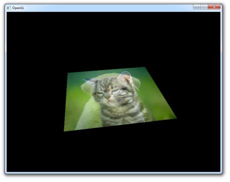
Figure 36:
60