

Figure 29:
Transformations in OpenGL
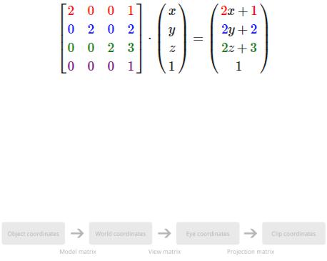
You’ve seen in the previous sections how basic transformations can be applied to vectors to move them around in the world. The job of transforming 3D points into 2D coordinates on your screen is also accomplished through matrix transformations. Just like the graphics pipeline, transforming a vector is done step-by-step. Although OpenGL allows you to decide on these steps yourself, all 3D graphics applications use a variation of the process described here.
Figure 30:
Each transformation transforms a vector into a new coordinate system, thus moving to the next step. These transformations and coordinate systems will be discussed below in more detail.
Model matrix
The model matrix transforms a position in a model to the position in the world. This position is a ected by the position, scale and rotation of the model that is being drawn. It is generally a combination of the simple transformations you’ve seen before. If you are already specifying your vertices in world coordinates (common when drawing a simple test scene), then this matrix can simply be set to the identity matrix.
View matrix
In real life you’re used to moving the camera to alter the view of a certain scene, in OpenGL it’s the other way around. The camera in OpenGL cannot move and is defined to be located at (0,0,0) facing the negative Z direction. That means
53
that instead of moving and rotating the camera, the world is moved and rotated around the camera to construct the appropriate view.
Older versions of OpenGL forced you to use ModelView and Projection transformations. The ModelView matrix combined the model and view transformations into one. I personally find it is easier to separate the two, so the view transformation can be modified independently of the model matrix.
That means that to simulate a camera transformation, you actually have to transform the world with the inverse of that transformation. Example: if you want to move the camera up, you have to move the world down instead.
Projection matrix
After the world has been aligned with your camera using the view transformation, the projection transformation can be applied, resulting in the clip coordinates. If you’re doing a perspective transformation, these clip coordinates are not ready to be used as normalized device coordinates just yet.
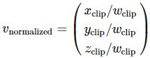
To transform the clipping coordinate into a normalized device coordinate, perspective division has to be performed. A clipping coordinate resulting from a perspective projection has a number di erent than 1 in the fourth row, also known as w. This number directly reflects the e ect of objects further away being smaller than those up front.
Figure 31:
The x and y coordinates will be in the familiar -1 and 1 range now, which OpenGL can transform into window coordinates. The z is known as the depth and will play an important role in the next chapter.
The coordinates resulting from the projection transformation are called clipping coordinates because the value of w is used to determine whether an object is too close or behind the camera or too far away to be drawn. The projection matrix is created with those limits, so you’ll be able to specify these yourself.
54