


26 |
Introduction to Direction-of-Arrival Estimation |
Figure 2.6 Antenna and its equivalent circuit.
radiation resistor and equivalently send their energy into the air or a medium.
A typical relationship between the input power and the frequency is shown in Figure 2.7. Like the bandwidth definition for a resonant circuit, the difference between the two frequency points at which the power drops to the half of its maximum is defined as the bandwidth of an antenna. Within the bandwidth, we consider that the degree of the power radiation is acceptable.
2.2 Single Receive Antenna
As mentioned before, a receive antenna does the opposite of a transmit antenna: it captures and intercepts electromagnetic energy in air or a medium and converts it to currents and voltages. Theoretically, a receive antenna should also have its own parameters that quantify its performance. In particular, it should have its own receive directivity, gain, and
|
P |
|
||
|
input |
|
||
|
P |
Bandwidth |
||
|
|
|||
|
m |
= f H - f L |
||
1 |
|
|
|
|
P |
|
|||
|
|
|||
2 m |
|
|
|
|
|
fL fH |
f |
||
|
fresonance |
|
||
Figure 2.7 A typical relationship between the frequency and the power input to an antenna.

Antennas and Array Receiving System |
27 |
|
|
pattern that describe how a receive antenna captures different energy amounts of electromagnetic or radio signals coming from different directions in reference to an omnidirectional receive antenna. However, it has been found and can be proven that these parameters have the same values or shape as the transmit directivity, gain, and pattern when the same antenna is used as a transmit antenna. As a result, in almost all the antenna analysis, directivity, gain, and radiation pattern are referred to those when an antenna is used for transmission. In other words, when an antenna is to be used for receiving, its receive parameters are simply taken from those transmit parameters when the antenna is analyzed for transmission; the exception is, however, the equivalent circuit.
The equivalent circuit of a receive antenna is shown in Figure 2.8. It is exactly the same as the equivalent circuit of the antenna when it is used for transmission, except a voltage or current source is added. The current source represents the equivalent current induced by the presence of the electromagnetic fields near the receive antenna. The resistances, inductance, and capacitance remain the same as those of the transmit antenna.
2.3 Antenna Array
An antenna array is a group of antennas that are used for transmitting or receiving the same signals. Each individual antenna is often called an array element. For a receive array, the signals received by all array elements will be combined and then processed for various applications, including the DOA estimations.
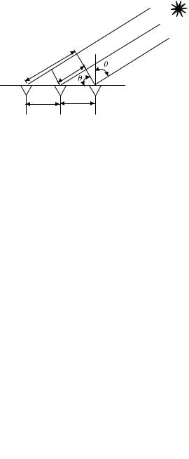
For illustration purposes, let us consider a three-element that is aligned uniformly along a line as shown in Figure 2.9. The rightmost
Electromagnetic waves
Antenna |
Current source |
|
|
|
|
|
|
|
|
C |
L |
|
R radiation |
ROhmic |
|
Equivalent Circuit
Figure 2.8 Equivalent circuit of a receive antenna.
28 |
Introduction to Direction-of-Arrival Estimation |
Source
Path 3
Path 2
Path 1
3
2
Element 3 Element 2 Element 1
Figure 2.9 Configuration of a three-element antenna array.
element is numbered as element 1 and taken as the reference element. The other two elements are numbered as element 2 and element 3 in a sequence from right to left. The distance between two neighboring elements is . A source emits electromagnetic waves at such a far distance that the three propagation line paths from the source to the three elements can be approximately considered as parallel. The waves impinge on the array at an angle of θ. As a result, the line paths from the source to elements 2 and 3 are longer than the path to element 1 (reference element) by the extra distance of
m = (m − 1) sin θ m =1, 2, 3 |
(2.1) |
Now assume that the wave signal received by the reference element (i.e., element 1) is
x1 (t ) = s (t ) |
(2.2) |
without taking into account of noises from air. Then the signals received by element 2 and element 3 can be written as:
x 2 (t ) = s (t )e − j β 2
x 3 (t ) = s (t )e − j β 3
=s (t )e
=s (t )e
− j |
2π |
sin θ |
||
|
||||
|
|
λ |
|
|
− j 2 |
2π |
|
sin θ |
|
λ |
|
|||
|
|
|
|
|
(2.3)
(2.4)

Antennas and Array Receiving System |
29 |
|
|
Here β = 2π is the phase shift constant of the wave propagating in air
λ
with λ being the wavelength. The phase shift term e − j β m in (2.3) and (2.4) is the result of the signal propagating over an extra distance m in comparison with the path to the rightmost element [1].
In a more generalized way, the signals received by the three elements can be written as:
x |
1 |
(t ) |
|
|
|
1 |
|
|
|
|
|
|
λ |
x = x 2 (t ) |
|
− j |
2π |
|||
= e |
|
2π |
||||
x |
3 |
(t ) |
|
− j 2 |
λ |
|
|
|
e |
|
|
||
|
|
|
1 |
|
|
|
sin θ |
s (t ) = |
e j μ |
|
= a(μ)s (t ) |
(2.5) |
|
|
||||||
|
|
|
|
|
|
|
sin θ |
e |
− j 2 μ |
|
|
||
|
|
|
|
|
|
|
where μ = |
|
2π |
|
sin θ and a(μ) = [1 e − j μ |
e − j 2 μ ]T , which is often called |
||||||||||||
|
λ |
|
|||||||||||||||
|
|
|
|
|
|
|
|
|
|
|
|
|
|
|
|
|
|
the array steering vector. |
|
|
|
|
|
|
|
|
|
||||||||
Equation (2.5) can be extended to an M-element array. It can be |
|||||||||||||||||
rewritten as: |
|
|
|
|
|
|
|
|
|
|
|
|
|
|
|||
|
x |
1 ( |
|
|
|
1 |
|
|
|
|
|
|
1 |
|
|
||
|
|
t ) |
|
|
|
|
λ |
|
|
|
|
|
|
|
|
||
|
|
|
|
|
|
|
|
|
− j μ |
||||||||
x = x 2 (t ) |
|
|
− j |
2π |
sin θ |
|
|
|
|
|
|
|
|||||
= |
e |
|
s |
(t ) = |
e |
|
|
s (t ) = a(μ)s (t ) (2.6) |
|||||||||
|
|
|
|
|
|
||||||||||||
|
|
|
|
|
|
|
|
|
|
|
|
|
|
|
|
||
|
|
|
|
|
|
− j ( M −1) |
2π |
sin θ |
|
|
− j ( M −1) |
μ |
|||||
x |
3 (t ) |
e |
|
|
|
λ |
|
|
e |
|
|
|
|
||||
|
|
|
|
|
|
|
|
|
|
|
|
|
|
|
|
|
|
and |
|
|
|
|
|
|
|
|
[ |
|
|
|
|
|
|
] |
|
|
|
|
|
|
|
a(μ) = |
|
|
|
− j ( M −1) μ |
|
||||||
|
|
|
|
|
|
1 e |
− j μ |
|
T |
|
|||||||
|
|
|
|
|
|
e |
|
|
|
|
|
||||||
Although (2.6) is for a linear array, the expression x = a(μ)s(t) is applicable to any other arrays.
2.4 Conclusion
In this chapter, we have reviewed the basic concepts of antennas and antenna arrays pertinent to the DOA estimation algorithms to be discussed in this book. In short, an antenna is a transducer device that interfaces electronic devices with air (or a medium) for the purpose of