

Preface
Direction-of-arrival (DOA) estimation (or direction finding) essentially concerns the estimation of direction-of-arrival of signals, either in the form of electromagnetic (i.e., radio) or acoustic waves, impinging on a sensor or antenna array. The requirement for DOA estimation arises from the needs of locating and tracking signal sources in both civilian and military applications, such as search and rescue, law enforcement, sonar, seismology, and wireless 911 emergency call locating.
Various theories and techniques have been developed for array signal processing related to DOA estimations. A large body of literature has also existed on the subject. However, during our course of research and development for real-world implementations, we have found that relevant publications have been quite scattered, making it hard for the beginners or students who want to enter the area in a relatively short time. In other words, few review books are available that systematically describe the principles and basic techniques of DOA estimation under one roof.
This book is intended to cover the issue by providing an overview and performance analysis of the basic DOA algorithms and comparisons among themselves. In particular, systematic descriptions, performance analysis, and comparisons of various DOA algorithms are presented with a final focus on the family of ESPRIT (estimation of signal parameters via rotational invariance techniques).
This book is aimed at beginners such as graduate students or engineers or government regulators who need to gain insight into the fundamentals of DOA estimations in a relatively quick manner. It is also
9
10 |
Introduction to Direction-of-Arrival Estimation |
suitable for those who specialize in the area but would like to refresh their knowledge of the basics of DOA estimations. It is our hope that this book can present sufficient information on theoretical foundations of DOA estimation techniques to a reader so that he or she can understand DOA basics and move on to advanced DOA topics if he or she wishes.
1
Introduction
Wireless technology applications have spread into many areas, such as environmental monitoring, sensor networks, public security, and search and rescues. In light of these developments, many technological policies have been established to accommodate the needs of various demands. For instance, a mandatory rule was passed by the FCC [1] that requires 125-m location accuracy on wireless emergency calls. As well, search and rescue always require the location of electromagnetic beacon sources. All these applications perhaps can be counted as the main reason for the recent increased interest in determining the direction of arrival (DOA) of radio signals in wireless systems. In fact, estimating the direction of arrival of several radio signals impinging on an array of sensors is required in a variety of other applications as well, including radar, sonar, and seismology. Another technology that has become equally glamorous is smart antenna technology [2, 3]. In smart antenna technology, a DOA estimation algorithm is usually incorporated to develop systems that provide accurate location information for wireless services [4].
A smart antenna, for this book discussion, is a system that combines multiple antenna elements with a signal processing capability to optimize its radiation and/or reception pattern automatically in response to the system’s signal environment. This technology is particularly found useful in mobile communications in lieu of an increasing number of mobile subscribers and limited resources. Smart antennas can be used to enhance the coverage through range extension and to increase system capacity [2, 3]. Smart antennas can also be used to spatially separate signals, allowing
11
12 |
Introduction to Direction-of-Arrival Estimation |
different subscribers to share the same spectral resources, provided that they are spatially separable at the base station. This spatial division multiple access (SDMA) method allows multiple users to operate in the same cell and on the same frequency/time slot provided by utilizing the adaptive beamforming techniques of the smart antennas. Since this approach allows more users to be supported within a limited spectrum allocation, compared with conventional antennas, SDMA can lead to improved capacity.
The smart antenna technology can be divided into three major categories depending on their choice in transmit strategy:
•Switched lobe (SL): This is the simplest technique and comprises only a basic switching function between predefined beams of an array. When a signal is received, the setting that gives the best performance, usually in terms of received power, is chosen for the system to operate with.
•Dynamically with phased array (PA): This technique allows continuous tracking of signal sources by including a direction-of-arrival (DOA) finding algorithm in the system; as a result, the transmission from the array can be controlled intelligently based on the DOA information of the array. The PA technique can be viewed as a generalization of the switched lobe concept.
•Adaptive array (AA): In this case, a DOA algorithm for determining the directions of interference sources (e.g., other users) is also incorporated in addition to finding the DOA of the desired source. The beam pattern can then be adjusted to null out the interferers while maximizing the transmit power at the desired source.
The importance of DOA estimation for smart antenna can be understood by studying the architecture of smart antenna as described in the following section.
1.1 Smart Antenna Architecture
Typical smart antenna architectures for a base station can be divided into following functional blocks, as shown in Figures 1.1 and 1.2:

Introduction |
13 |
|
|
R adio Unit
Figure 1.1 Smart antenna receiver.
Beamforming Unit |
|
W1 |
|
W2 |
To Receiving |
|
|
|
Base Station |
W3 |
|
W4 |
|
Adaptive Antenna
Processor
•Radio unit: This unit mainly consists of: (1) antenna arrays that intercept radio frequency (RF) signals from the air, (2) downconversion chains that remove the carrier(s) of the RF signals received by the antenna array, and (3) analog-to-digital converters that convert the no-carrier signals to the corresponding digital signals for further processing. Antenna arrays can be one-, two-, or even three-dimensional, depending on the dimension of the space one wants to access. The radiation pattern of the array depends on the element type, the relative positions, and the excitation (amplitude and phase) to each element [5].
•Beamforming unit: The beamforming unit is responsible for forming and steering the beam in the desired direction. In it, the weighting of the received (or transmitted) signals is applied. Basi-
cally, the data signals xk, k = 0, …, M − 1 received by an M-element array are directly multiplied by a set of weights to form a beam at a desired angle. In other words, by multiplying the data signals with appropriate sets of weights, it is possible to form a set of beams with pointing angles directed at the desired angles, resulting in a signal peak at the output of a beamformer. Mathemati-
cally it can be expressed as:
14 |
Introduction to Direction-of-Arrival Estimation |
Input Data |
|
|
Model Order |
MDL |
|
Estimator |
AIC |
|
DOA |
ESPRIT |
|
Estimator |
PAST |
|
Spatial Filter |
MOORE |
|
PENROSE |
||
|
||
User |
DDF |
|
Identification |
SDF |
|
User Tracking |
CSD |
|
CD |
||
|
||
Weight |
LMS |
|
Generation |
SMI |
Uplink and Downlink Weights
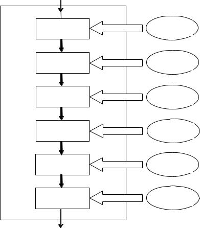
Figure 1.2 Adaptive antenna processor.
M −1 |
|
y (θi ) = ∑ w ki xk |
(1.1) |
k = 0
where y(θi) is the output of a beamformer, xk is the data sample from the kth array element and wki is the weight for forming a beam or null at angle θi. More descriptions on (1.1) are given in Chapters 2 and 3.
By selecting the appropriate values for the set of the weights
w i = = , one can implement beam steering, adaptive nulling,
k k 0,, , M 1
Introduction |
15 |
|
|
and beamshaping. These weights that determine the radiation pattern are generated by the adaptive processor unit.
•Adaptive antenna processor: The function of the adaptive processor unit is to determine the complex weights for the beamforming unit. The weights can be optimized from two main types of criteria: maximization of the data signal from the desired source (e.g., switched lobe or phased array) or maximization of the signal-to-interference ratio (SIR) by suppressing the signal
from the interference sources (adaptive array). In theory with M antenna elements, one can “null out” M − 1 interference sources, but due to multipath propagation, this number will be normally lower. The method for calculating the weights will differ depending on the types of optimization criteria. When a switched lobe is used, the receiver will test all the predefined weights and choose the one that gives the strongest received data signal. However, if the phased array or adaptive array approach is used, which consists of directing a maximum gain towards the strongest signal component, the directions of arrival (DOAs) of the signals are first estimated and the weights are then calculated in accordance with the desired steering angle.
In general, as shown in Figure 1.2, the adaptive antenna processor consists of several computation processes:
•Model order estimator: From the input data xk, k = 0, …, M − 1 received by the antenna elements, the number of wavefronts impinging on the array is estimated using model order estimation algorithms, such as AIC or MDL, which will be described in Chapter 4. The knowledge of number of the signals impinging on the array is crucial to DOA estimation algorithms; hence, these algorithms are run prior to DOA estimation algorithms.
•DOA estimator: This forms the vital stage of the adaptive antenna processor where algorithms like MUSIC or ESPRIT are used for estimating the direction of arrival of all the signals impinging on the array. This stage gives DOAs of all the relevant signals of the user sources and other interference sources. To make the process faster, instead of estimating the signal space every time, subspace tracking algorithms like dPAST and PAST (Projection
16 |
Introduction to Direction-of-Arrival Estimation |
Approximation Subspace Tracking) are used to recursively track the signal subspace. Usually, the signal subspace is only slowly time-varying. It is therefore more efficient to track those changes than to perform full subspace estimation. The DOAs can then be estimated faster from these signal subspaces. Detailed descriptions of these DOA algorithms are presented in Chapter 3, 4, and 5.
•Spatial filter: After the DOAs of all the signals impinging on the array are obtained, the signals are filtered by reconstructing the signals for each of the DOAs estimated. Estimating the signals from the estimated DOAs is usually called signal reconstruction or signal copy. With the knowledge of DOAs, the corresponding steering vectors a and eventually the estimated steering matrix A are constructed. The signal is then reconstructed from
S = WX
where S is the matrix of impinging signals extracted from the noise corrupted signals (or data signals) received by an array X and the weighting matrix W is chosen to be the Moore-Penrose pseudo inverse of the estimated array steering matrix A. More details are given in Chapter 3.
•User identification: Once the signals are separated with respect to their distinct DOAs, the desired user corresponding to these DOAs needs to be identified. By comparing the received mid-ambles (training sequences) with the desired user mid-amble, the number of bit errors within the training sequence can be calculated. A spatially resolved wavefront and thus the corresponding DOA are attributed to a user, when the number of bit errors is smaller than a threshold. In this way not only a single user path but also all paths that correspond to the intended user can be identified. The DOA of the user path with the strongest instantaneous power is then detected. As a training sequence detector, standard sequence estimators like delayed decision feedback (DDF) and soft decision feedback (SDF) are applied [6].
•User tracking: A fast reactive adaptive estimator is needed for tracking changes of signal parameters. The tracker does not only prevent far-off estimates from disturbing the beamforming, but also prevents the DOA estimates from changing too much