

CCNA_R&S-Student_Lab_Manual
.pdfLab 27 – Managing Router Configuration Files with Terminal Emulation Software
Part 191: Topology
Part 192: Addressing Table
|
|
|
Subnet |
Default |
Device |
Interface |
IP Address |
Mask |
Gateway |
|
|
|
|
|
|
|
|
255.255.255. |
|
R1 |
G0/1 |
192.168.1.1 |
0 |
N/A |
|
|
|
|
|
|
|
192.168.1.1 |
255.255.255. |
|
S1 |
VLAN 1 |
1 |
0 |
192.168.1.1 |
|
|
|
|
|
|
|
|
255.255.255. |
|
PC-A |
NIC |
192.168.1.3 |
0 |
192.168.1.1 |
|
|
|
|
|
Part 193: Objectives
Part 1: Configure Basic Device Settings
Part 2: Use Terminal Emulation Software to Create a Backup Configuration File Part 3: Use a Backup Configuration File to Restore a Router
Part 194: Background / Scenario
It is a recommended best practice to maintain backup configuration files for routers and switches in the event that they need to be restored to a previous configuration. Terminal emulation software can be used to easily back up or restore a router or switch configuration file.
In this lab, you will use Tera Term to back up a router running configuration file, erase the router startup configuration file, reload the router, and then restore the missing router configuration from the backup configuration file.
Note: The routers used with CCNA hands-on labs are Cisco 1941 Integrated Services Routers (ISRs) with Cisco IOS Release 15.2(4)M3 (universalk9 image). The switches used are Cisco Catalyst 2960s with Cisco IOS Release 15.0(2) (lanbasek9 image). Other routers, switches, and Cisco IOS versions can be used. Depending on the model and Cisco IOS version, the commands available and output produced might vary from what is shown in the labs. Refer to the Router Interface Summary Table at the end of this lab for the correct interface identifiers.
Note: Make sure that the routers and switches have been erased and have no startup configurations. If you are unsure, contact your instructor.
Part 195: Required Resources
1 Router (Cisco 1941 with Cisco IOS Release 15.2(4)M3 universal image or comparable)
© 2013 Cisco and/or its affiliates. All rights reserved. This document is Cisco Public. Page 231 of 257

1 Switch (Cisco 2960 with Cisco IOS Release 15.0(2) lanbasek9 image or comparable) 1 PC (Windows 7, Vista, or XP with terminal emulation program, such as Tera Term) Console cables to configure the Cisco IOS devices via the console ports
Ethernet cables as shown in the topology
Part 196: Configure Basic Device Settings
In Part 1, you will set up the network topology and configure basic settings, such as the interface IP addresses, device access, and passwords on the router.
Step 1: Cable the network as shown in the topology.
Attach the devices as shown in the topology and cable as necessary.
Step 2: Configure the PC-A network settings according to the Addressing Table. Step 3: Initialize and reload the router and switch.
Step 4: Configure the router.
a.Console into the router and enter global configuration mode.
b.Set the router name to R1.
c.Disable DNS lookup.
d.Assign class as the privileged EXEC encrypted password.
e.Assign cisco as the console password and enable login.
f.Assign cisco as the vty password and enable login.
g.Encrypt the plain text passwords.
h.Create a banner that warns anyone accessing the device that unauthorized access is prohibited.
i.Configure and activate the G0/1 interface on the router using the information contained in the Addressing Table.
j.Save the running configuration to the startup configuration file.
Step 5: Configure the switch.
a.Console into the switch and enter into global configuration mode.
b.Set the switch name to S1.
c.Disable DNS lookup.
d.Assign class as the privileged EXEC encrypted password.
e.Assign cisco as the console password and enable login.
f.Assign cisco as the vty password and enable login.
g.Encrypt the plain text passwords.
h.Create a banner that warns anyone accessing the device that unauthorized access is prohibited.
i.Configure the default SVI management interface with the IP address information contained in the Addressing Table.
j.Configure the switch default gateway.
© 2013 Cisco and/or its affiliates. All rights reserved. This document is Cisco Public. Page 232 of 257

k.Save the running configuration to the startup configuration file.
Part 197: Use Terminal Emulation Software to Create a Backup Configuration File
Step 1: Establish a Tera Term console session to the router.
Launch the Tera Term Program, and in the New Connection window, select the Serial radio button and the appropriate communications port for your PC (i.e., COM1).
Note: If Tera Term is not installed, you can download the latest version from a number of Internet sites. Simply search for a Tera Term download.
a.In Tera Term, press Enter to connect to the router.
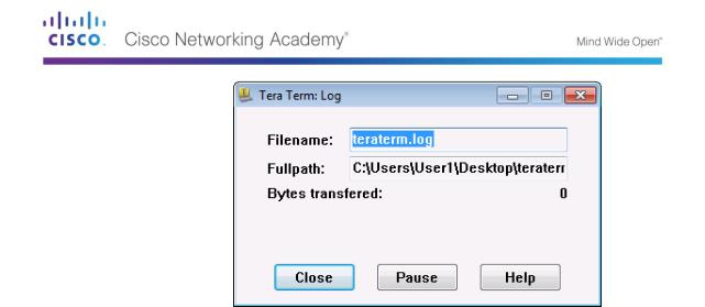
b.From the File menu, choose Log…, and save the teraterm.log file to the Desktop. Ensure that the Append and Plain text check boxes are enabled (checked).
c.The Tera Term log file will create a record of every command issued and every output displayed.
Note: You can use this feature to capture the output from several commands in sequence and use it for network documentation purposes. For example, you could issue the show version, show ip interface brief, and show running-config commands to capture information about the router.
Step 2: Display the router running-configuration.
a.Use the console password to log in to the router.
b.Enter privileged EXEC mode.
c.Enter the show running-config command.
d.Continue pressing the space bar when --More-- is displayed until you see the router R1# prompt return.
e.Click the Tera Term: Log icon on the Task bar. Click Close to end log session.
©2013 Cisco and/or its affiliates. All rights reserved. This document is Cisco Public.
Page 233 of 257
Note: You can also copy and paste the text from the Tera Term window directly into a text editor.
Part 198: Use a Backup Configuration File to Restore a Router
Step 1: Erase the router startup-configuration and reload.
a.From privileged EXEC mode erase the startup configuration.
R1# erase startup-config
Erasing the nvram filesystem will remove all configuration files! Continue? [confirm]
[OK]
Erase of nvram: complete
b.Reload the router.
R1# reload
Proceed with reload? [confirm]
c.At the System Configuration Dialog prompt, type no; a router prompt displays, indicating an unconfigured router.
---System Configuration Dialog ---
Would you like to enter the initial configuration dialog? [yes/no]:
Press RETURN to get started! <output omitted>
Router>
d.Enter privileged EXEC mode and enter a show running-config command to verify that all of the previous configurations were erased.
Step 2: Edit the saved configuration backup file to prepare it for restoring the router configuration.
To restore the router configuration from a saved running configuration backup file, you must edit the text.
a.Open the teraterm.log text file.
b.Remove each instance of --More-- in the text file.
Note: The --More-- was generated by pressing the Spacebar when displaying the running configuration.
©2013 Cisco and/or its affiliates. All rights reserved. This document is Cisco Public.
Page 234 of 257

c.Delete the initial lines of the backup configuration file, so that the first line starts with the first configuration command as shown below.
service timestamps debug datetime msec service timestamps log datetime msec service password-encryption
d.Replace the encrypted secret password.
enable secret 4 06YFDUHH61wAE/kLkDq9BGho1QM5EnRtoyr8cHAUg.2
Change to:
enable secret class
e.In the lines for interface GigabitEthernet0/1, insert a new line to enable the interface. interface GigabitEthernet0/1
ip address 192.168.1.1 255.255.255.0 duplex auto
speed auto
Change to:
interface GigabitEthernet0/1
ip address 192.168.1.1 255.255.255.0 duplex auto
speed auto no shutdown
f.Change the message-of-the-day (MOTD) banner configuration to insert the delimiting characters as if you were entering the command at the command line.
banner motd ^C Unauthorized Access is Prohibited! ^C
Change to:
banner motd “ Unauthorized Access is Prohibited! “
g.In line con 0 and vty 0 4 sections, replace the encrypted password. line con 0
password 7 104D000A0618 line vty 0 4
password 7 104D000A0618
Change to: line con 0
password cisco line vty 0 4
password cisco
h.After you have made all of the edits to the backup configuration file, save your changes to filename, R1-config-backup.
Note: When saving the file, an extension, such as .txt, may be added to the filename automatically.
Step 3: Restore the router configuration.
You can restore the edited running configuration directly to the console terminal in router global configuration mode, and the configurations are entered as if they were commands entered individually at the command prompt.
© 2013 Cisco and/or its affiliates. All rights reserved. This document is Cisco Public. Page 235 of 257

a.From the Tera Term console connection to the router, enter global configuration mode.
b.From the File menu, select Send file….
c.Locate R1-config-backup and select Open.
d.Save the running configuration to the startup configuration file.
R1# copy running-config startup-config
e.Verify the new running configuration.
Step 4: Back up and restore the switch.
Go back to the beginning of Part 2 and follow the same steps to backup and restore the switch configuration.
Part 199: Reflection
Why do you think it is important to use a text editor instead of a word processor to copy and save your command configurations?
_____________________________________________________________________________
__________
_____________________________________________________________________________
__________
_____________________________________________________________________________
__________
© 2013 Cisco and/or its affiliates. All rights reserved. This document is Cisco Public. Page 236 of 257

Lab 28 – Managing Device Configuration Files Using TFTP, Flash, and USB
Topology
Addressing Table
Device |
Interface |
IP Address |
Subnet Mask |
Default Gateway |
|
|
|
|
|
R1 |
G0/1 |
192.168.1.1 |
255.255.255.0 |
N/A |
|
|
|
|
|
S1 |
VLAN 1 |
192.168.1.11 |
255.255.255.0 |
192.168.1.1 |
|
|
|
|
|
PC-A |
NIC |
192.168.1.3 |
255.255.255.0 |
192.168.1.1 |
|
|
|
|
|
Objectives
Part 1: Build the Network and Configure Basic Device Settings
Part 2: (Optional) Download TFTP Server Software
Part 3: Use TFTP to Back Up and Restore the Switch Running Configuration Part 4: Use TFTP to Back Up and Restore the Router Running Configuration
Part 5: Back Up and Restore Running Configurations Using Router Flash Memory Part 6: (Optional) Use a USB Drive to Back Up and Restore the Running Configuration
Background / Scenario
Cisco networking devices are often upgraded or swapped out for a number of reasons. It is important to maintain backups of the latest device configurations, as well as a history of configuration changes. A TFTP server is often used to backup configuration files and IOS images in production networks. A TFTP server is a centralized and secure method used to store the backup copies of the files and restore them as necessary. Using a centralized TFTP server, you can back up files from many different Cisco devices.
In addition to a TFTP server, most of the current Cisco routers can back up and restore files locally from CompactFlash (CF) memory or a USB flash drive. The CF is a removable memory module that has replaced the limited internal flash memory of earlier router models. The IOS image for the router resides in the CF memory, and the router uses this IOS Image for the boot process. With the larger size of the CF memory, additional files can be stored for backup purposes. A removable USB flash drive can also be used for backup purposes.
In this lab, you will use TFTP server software to back up the Cisco device running configuration to the TFTP server or flash memory. You can edit the file using a text editor and copy the new configuration back to a Cisco device.
© 2013 Cisco and/or its affiliates. All rights reserved. This document is Cisco Public. Page 237 of 257

Note: The routers used with CCNA hands-on labs are Cisco 1941 Integrated Services Routers (ISRs) with Cisco IOS Release 15.2(4)M3 (universalk9 image). The switches used are Cisco Catalyst 2960s with Cisco IOS Release 15.0(2) (lanbasek9 image). Other routers, switches, and Cisco IOS versions can be used. Depending on the model and Cisco IOS version, the commands available and output produced might vary from what is shown in the labs. Refer to the Router Interface Summary Table at the end of this lab for the correct interface identifiers.
Note: Make sure that the routers and switches have been erased and have no startup configurations. If you are unsure, contact your instructor.
Required Resources
1 Router (Cisco 1941 with Cisco IOS Release 15.2(4)M3 universal image or comparable)
1 Switch (Cisco 2960 with Cisco IOS Release 15.0(2) lanbasek9 image or comparable)
1 PC (Windows 7, Vista, or XP with terminal emulation program, such as Tera Term, and a TFTP server)
Console cables to configure the Cisco IOS devices via the console ports
Ethernet cables as shown in the topology
USB flash drive (Optional)
Part 200: Build the Network and Configure Basic Device Settings
In Part 1, you will set up the network topology and configure basic settings, such as the interface IP addresses for router R1, switch S1 and PC-A.
Step 1: Cable the network as shown in the topology.
Attach the devices as shown in the topology diagram, and cable as necessary.
Step 2: Initialize and reload the router and switch.
Step 3: Configure basic settings for each device.
a.Configure basic device parameters as shown in the Addressing Table.
b.To prevent the router and switch from attempting to translate incorrectly entered commands as though they were host names, disable DNS lookup.
c.Assign class as the privileged EXEC encrypted password.
d.Configure the passwords and allow login for console and vty lines using the cisco as the password.
e.Configure the default gateway for the switch.
f.Encrypt the clear text passwords.
g.Configure the IP address, subnet mask, and default gateway for PC-A.
Step 4: Verify connectivity from PC-A.
a.Ping from PC-A to S1.
b.Ping from PC-A to R1.
If the pings are not successful, troubleshoot the basic device configurations before continuing.
Part 201: (Optional) Download TFTP Server Software
A number of free TFTP servers are available on the Internet for download. The Tftpd32 server is used with this lab.
© 2013 Cisco and/or its affiliates. All rights reserved. This document is Cisco Public. Page 238 of 257

Note: Downloading a TFTP server from a website requires Internet access.
Step 1: Verify availability of a TFTP server on PC-A.
a.Click the Start menu and select All Programs.
b.Search for a TFTP server on PC-A.
c.If a TFTP server is not found, a TFTP server can be downloaded from the Internet.
Step 2: Download a TFTP server.
a.Tftpd32 is used in this lab. This server can be downloaded from the following link: http://tftpd32.jounin.net/tftpd32_download.html
b.Choose the appropriate version for your system and install the server.
Part 202: Use TFTP to Back Up and Restore the Switch Running Configuration
Step 1: Verify connectivity to switch S1 from PC-A.
The TFTP application uses the UDP Layer 4 transport protocol, which is encapsulated in an IP packet. For TFTP file transfers to function, there must be Layer 1 and 2 (Ethernet, in this case) and Layer 3 (IP) connectivity between the TFTP client and the TFTP server. The LAN topology in this lab uses only Ethernet at Layers 1 and 2. However, TFTP transfers can also be accomplished over WAN links that use other Layer 1 physical links and Layer 2 protocols. As long as there is IP connectivity between the client and server, as demonstrated by ping, the TFTP transfer can take place. If the pings are not successful, troubleshoot the basic device configurations before continuing.
Note: A common misconception is that you can TFTP a file over the console connection. This is not the case because the console connection does not use IP. The TFTP transfer can be initiated from the client device (router or switch) using the console connection, but there must be IP connectivity between the client and server for the file transfer to take place.
Step 2: Start the TFTP server.
a.Click the Start menu and select All Programs.
b.Find and select Tftpd32 or Tftpd64. The following window displays that the TFTP server is ready.
© 2013 Cisco and/or its affiliates. All rights reserved. This document is Cisco Public. Page 239 of 257

c.Click Browse to choose a directory where you have write permission, such as C:\Users\User1, or the Desktop.
Step 3: Explore the copy command on a Cisco device.
a.Console into switch S1 and, from the privileged EXEC mode prompt, enter copy ? to display the options for source or “from” location and other available copy options. You can specify flash: or flash0: as the source, however, if you simply provide a filename as the source, flash0: is assumed and is the default. Note that running-config is also an option for the source location.
S1# copy ?
/erase |
Erase destination file system. |
/error |
Allow to copy error file. |
/noverify |
Don't verify image signature before reload. |
/verify |
Verify image signature before reload. |
archive: |
Copy from archive: file system |
cns: |
Copy from cns: file system |
flash0: |
Copy from flash0: file system |
flash1: |
Copy from flash1: file system |
flash: |
Copy from flash: file system |
ftp: |
Copy from ftp: file system |
http: |
Copy from http: file system |
https: |
Copy from https: file system |
null: |
Copy from null: file system |
nvram: |
Copy from nvram: file system |
rcp: |
Copy from rcp: file system |
running-config |
Copy from current system configuration |
scp: |
Copy from scp: file system |
startup-config |
Copy from startup configuration |
system: |
Copy from system: file system |
tar: |
Copy from tar: file system |
tftp: |
Copy from tftp: file system |
tmpsys: |
Copy from tmpsys: file system |
© 2013 Cisco and/or its affiliates. All rights reserved. This document is Cisco Public. Page 240 of 257