CCNA_R&S-Student_Lab_Manual
.pdf
INTRODUCTION TO NETWORKS |
|
TABLE OF CONTENTS |
|
Lab 1 - Initializing and Reloading a Router and Switch ..................................................... |
3 |
Lab 2 - Establishing a Console Session with Tera Term..................................................... |
7 |
Lab 3 - Building a Simple Network ................................................................................. |
18 |
Lab 4 - Configuring a Switch Management Address ......................................................... |
32 |
Lab 5 - Using Wireshark to View Network Traffic ............................................................ |
40 |
Lab 6 - Identifying Network Devices and Cabling ............................................................ |
60 |
Lab 7 - Building an Ethernet Crossover Cable ................................................................. |
63 |
Lab 8 – Viewing Wireless and Wired NIC Information...................................................... |
69 |
Lab 9 – Viewing Network Device MAC Addresses ............................................................ |
80 |
Lab 10 – Using Wireshark to Examine Ethernet Frames ................................................... |
87 |
Lab 11 – Observing ARP with the Windows CLI, IOS CLI, and Wireshark .......................... |
94 |
Lab 12 - Using IOS CLI with Switch MAC Address Tables ............................................... |
105 |
Lab 13 - Viewing Host Routing Tables.......................................................................... |
110 |
Lab 14 - Exploring Router Physical Characteristics......................................................... |
116 |
Lab 15 - Building a Switch and Router Network ............................................................ |
125 |
Lab 16 - Using Wireshark to Observe the TCP 3-Way Handshake ................................... |
136 |
Lab 17 - Using Wireshark to Examine a UDP DNS Capture ............................................. |
142 |
Lab 18 - Using Wireshark to Examine FTP and TFTP Captures ....................................... |
148 |
Lab 19 - Configuring IPv6 Addresses on Network Devices.............................................. |
162 |
Lab 20 – Testing Network Connectivity with Ping and Traceroute ................................... |
172 |
Lab 21 - Observing DNS Resolution ............................................................................. |
187 |
Lab 22 - Exploring FTP ............................................................................................... |
192 |
Lab 23 – Researching Network Security Threats ........................................................... |
201 |
Lab 24 - Accessing Network Devices with SSH .............................................................. |
205 |
Lab 25 – Securing Network Devices ............................................................................. |
218 |
Lab 26 - Testing Network Latency with Ping and Traceroute .......................................... |
226 |
Lab 27 – Managing Router Configuration Files with Terminal Emulation Software ............ |
231 |
Lab 28 – Managing Device Configuration Files Using TFTP, Flash, and USB ..................... |
237 |
Lab 29 – Researching Password Recovery Procedures ................................................... |
251 |
Lab 30 - Design and Build a Small Business Network (Capstone Project)......................... |
255 |
© 2013 Cisco and/or its affiliates. All rights reserved. This document is Cisco Public. |
|
Page 1 of 257 |
|

© 2013 Cisco and/or its affiliates. All rights reserved. This document is Cisco Public.
Page 2 of 257

Lab 1 - Initializing and Reloading a Router and Switch
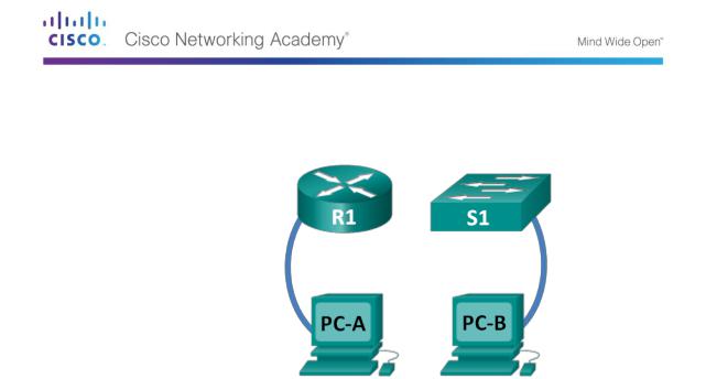
Topology
Objectives
Part 1: Set Up Devices in the Network as Shown in the Topology
Part 2: Initialize the Router and Reload
Part 3: Initialize the Switch and Reload
Background / Scenario
Before starting a CCNA hands-on lab that makes use of either a Cisco router or switch, ensure that the devices in use have been erased and have no startup configurations present. Otherwise, the results of your lab may be unpredictable. This lab provides a detail procedure for initializing and reloading a Cisco router and a Cisco switch.
Note: The routers used with CCNA hands-on labs are Cisco 1941 Integrated Services Routers (ISRs) with Cisco IOS Release 15.2(4)M3 (universalk9 image). The switches used are Cisco Catalyst 2960s with Cisco IOS Release 15.0(2) (lanbasek9 image). Other routers, switches, and Cisco IOS versions can be used. Depending on the model and Cisco IOS version, the commands available and output produced might vary from what is shown in the labs.
Required Resources
1 Router (Cisco 1941 with Cisco IOS software, Release 15.2(4)M3 universal image or comparable)
1 Switch (Cisco 2960 with Cisco IOS Release 15.0(2) lanbasek9 image or comparable)
2 PCs (Windows 7, Vista, or XP with terminal emulation program, such as Tera Term)
Console cables to configure the Cisco IOS devices via the console ports
Part 1: Set Up Devices in the Network as Shown in the Topology
Step 1: Cable the network as shown in the topology.
Attach console cables to the devices shown in the topology diagram.
Step 2: Power on all the devices in the topology.
Wait for all devices to finish the software load process before moving to Part 2.
© 2013 Cisco and/or its affiliates. All rights reserved. This document is Cisco Public. Page 3 of 257

Part 2: Initialize the Router and Reload
Step 1: Connect to the router.
Console into the router and enter privileged EXEC mode using the enable command.
Router> enable
Router#
Step 2: Erase the startup configuration file from NVRAM.
Type the erase startup-config command to remove the startup configuration from nonvolatile random-access memory (NVRAM).
Router# erase startup-config
Erasing the nvram filesystem will remove all configuration files! Continue? [confirm]
[OK]
Erase of nvram: complete Router#
Step 3: Reload the router.
Issue the reload command to remove an old configuration from memory. When prompted to Proceed with reload, press Enter to confirm the reload. Pressing any other key will abort the reload.
Router# reload
Proceed with reload? [confirm]
*Nov 29 18:28:09.923: %SYS-5-RELOAD: Reload requested by console. Reload Reason: Reload Command.
Note: You may receive a prompt to save the running configuration prior to reloading the router. Respond by typing no and press Enter.
System configuration has been modified. Save? [yes/no]: no
Step 4: Bypass the initial configuration dialog.
After the router reloads, you are prompted to enter the initial configuration dialog. Enter no and press Enter.
Would you like to enter the initial configuration dialog? [yes/no]: no
Step 5: Terminate the autoinstall program.
You will be prompted to terminate the autoinstall program. Respond yes and then press Enter.
Would you like to terminate autoinstall? [yes]: yes
Router>
Part 3: Initialize the Switch and Reload
Step 1: Connect to the switch.
Console into the switch and enter privileged EXEC mode.
Switch> enable
Switch#
© 2013 Cisco and/or its affiliates. All rights reserved. This document is Cisco Public. Page 4 of 257

Step 2: Determine if there have been any virtual local-area networks (VLANs) created.
Use the show flash command to determine if any VLANs have been created on the switch.
Switch# show flash
Directory of flash:/
2 |
-rwx |
1919 |
Mar 1 1993 00:06:33 +00:00 |
private-config.text |
||
3 |
-rwx |
1632 |
Mar 1 1993 |
00:06:33 +00:00 |
config.text |
|
4 |
-rwx |
13336 |
Mar 1 1993 |
00:06:33 +00:00 |
multiple-fs |
|
5 |
-rwx |
11607161 |
Mar 1 1993 |
02:37:06 +00:00 |
c2960-lanbasek9- |
|
mz.150-2.SE.bin |
|
|
|
|
|
|
|
|
|
|
|
|
|
6 |
-rwx |
616 |
Mar 1 1993 |
00:07:13 +00:00 |
vlan.dat |
|
32514048 bytes total (20886528 bytes free) Switch#
Step 3: Delete the VLAN file.
a.If the vlan.dat file was found in flash, then delete this file.
Switch# delete vlan.dat
Delete filename [vlan.dat]?
You will be prompted to verify the file name. At this point, you can change the file name or just press Enter if you have entered the name correctly.
b.When you are prompted to delete this file, press Enter to confirm the deletion. (Pressing any other key will abort the deletion.)
Delete flash:/vlan.dat? [confirm] Switch#
Step 4: Erase the startup configuration file.
Use the erase startup-config command to erase the startup configuration file from NVRAM. When you are prompted to remove the configuration file, press Enter to confirm the erase. (Pressing any other key will abort the operation.)
Switch# erase startup-config
Erasing the nvram filesystem will remove all configuration files! Continue? [confirm]
[OK]
Erase of nvram: complete Switch#
Step 5: Reload the switch.
Reload the switch to remove any old configuration information from memory. When you are prompted to reload the switch, press Enter to proceed with the reload. (Pressing any other key will abort the reload.)
Switch# reload
Proceed with reload? [confirm]
Note: You may receive a prompt to save the running configuration prior to reloading the switch. Type no and press Enter.
System configuration has been modified. Save? [yes/no]: no
© 2013 Cisco and/or its affiliates. All rights reserved. This document is Cisco Public. Page 5 of 257

Step 6: Bypass the initial configuration dialog.
After the switch reloads, you should see a prompt to enter the initial configuration dialog. Type no at the prompt and press Enter.
Would you like to enter the initial configuration dialog? [yes/no]: no Switch>
Reflection
1.Why is it necessary to erase the startup configuration before reloading the router?
_____________________________________________________________________________
__________
_____________________________________________________________________________
__________
2.You find a couple of configurations issues after saving the running configuration to the startup configuration, so you make the necessary changes to fix those issues. If you were to reload the device now, what configuration would be restored to the device after the reload?
_____________________________________________________________________________
__________
______________________________________________________________
© 2013 Cisco and/or its affiliates. All rights reserved. This document is Cisco Public. Page 6 of 257

Lab 2 - Establishing a Console Session with Tera Term
Topology
Objectives
Part 1: Access a Cisco Switch through the Serial Console Port
Connect to a Cisco switch using a serial console cable.
Establish a console session using a terminal emulator, such as Tera Term.
Part 2: Display and Configure Basic Device Settings
Use show commands to display device settings.
Configure the clock on the switch.
Part 3: (Optional) Access a Cisco Router Using a Mini-USB Console Cable
Note: Users on Netlab or other remote access equipment should complete only Part 2.
Background / Scenario
Various models of Cisco routers and switches are used in networks of all types. These devices are managed using a local console connection or a remote connection. Nearly all Cisco devices have a serial console port to which you can connect. Some newer models, such as the 1941 Integrated Services Router (ISR) G2 used in this lab, also have a USB console port.
In this lab, you will learn how to access a Cisco device via a direct local connection to the console port, using a terminal emulation program, Tera Term. You will also learn how to configure the serial port settings for the Tera Term console connection. After you have established a console connection with the Cisco device, you can display or configure device settings. You will only display settings and configure the clock with this lab.
Note: The routers used with CCNA hands-on labs are Cisco 1941 ISRs with Cisco IOS Release 15.2(4)M3 (universalk9 image). The switches used are Cisco Catalyst 2960s with Cisco IOS Release 15.0(2) (lanbasek9 image). Other routers, switches, and Cisco IOS versions can be used. Depending on the model and Cisco IOS version, the commands available and output produced might vary from what is shown in the labs. Refer to the Router Interface Summary Table at the end of the lab for the correct interface identifiers.
Note: Make sure that the switch and router have been erased and have no startup configuration. If you are unsure, contact your instructor.
Required Resources
1 Router (Cisco 1941 with Cisco IOS software, release 15.2(4)M3 universal image or comparable)
1 Switch (Cisco 2960 with Cisco IOS Release 15.0(2) lanbasek9 image or comparable)
1 PC (Windows 7, Vista, or XP with terminal emulation program, such as Tera Term)
Rollover (DB-9 to RJ-45) console cable to configure the switch or router via the RJ-45 console port
Mini-USB cable to configure the router via the USB console port
©2013 Cisco and/or its affiliates. All rights reserved. This document is Cisco Public.
Page 7 of 257

Part 4: Access a Cisco Switch through the Serial Console Port
You will connect a PC to a Cisco switch using a rollover console cable. This connection will allow you to access the command line interface (CLI) and display settings or configure the switch.
Step 1: Connect a Cisco switch and computer using a rollover console cable.
a.Connect the rollover console cable to the RJ-45 console port of the switch.
b.Connect the other cable end to the serial COM port on the computer.
Note: Serial COM ports are no longer available on most computers today. A USB-to-DB9 adapter can be used with the rollover console cable for console connection between the computer and a Cisco device. These USB-to-DB9 adapters can be purchased at any computer electronics store.
Note: If using a USB-to-DB9 adapter to connect to the COM port, you may be required to install a driver for the adapter provided by the manufacturer on your computer. To determine the COM port used by the adapter, please see Part 3 Step 4. The correct COM port number is required to connect to the Cisco IOS device using a terminal emulator in Step 2.
c.Power up the Cisco switch and computer if these devices are not already on.
Step 2: Configure Tera Term to establish a console session with the switch.
Tera Term is a terminal emulation program. This program allows you to access the terminal output of the switch. It also allows you to configure the switch.
a.Start Tera Term by clicking the Windows Start button located in the task bar. Locate Tera Term under All Programs.
Note: If the program is not installed on the system, Tera Term can be downloaded from the following link by selecting Tera Term:
http://logmett.com/index.php?/download/free-downloads.html
© 2013 Cisco and/or its affiliates. All rights reserved. This document is Cisco Public. Page 8 of 257

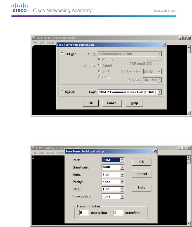
b.In the New Connection dialog box, click the Serial radio button. Verify that the correct COM port is selected and click OK to continue.
c.From the Tera Term Setup menu, choose the Serial port… to verify the serial settings. The default parameters for the console port are 9600 baud, 8 data bits, no parity, 1 stop bit, and no flow control. The Tera Term default settings match the console port settings for communications with the Cisco IOS switch.
© 2013 Cisco and/or its affiliates. All rights reserved. This document is Cisco Public. Page 9 of 257

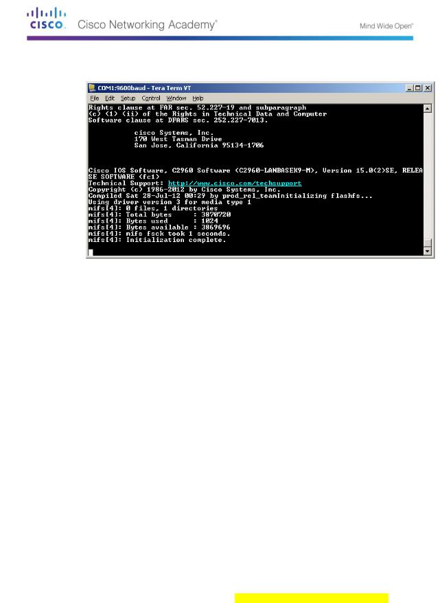
d.When you can see the terminal output, you are ready to configure a Cisco switch. The following console example displays the terminal output of the switch while it is loading.
Part 5: Display and Configure Basic Device Settings
In this section, you are introduced to the user and privileged executive modes. You will determine the Internetwork Operating System (IOS) version, display the clock settings, and configure the clock on the switch.
Step 1: Display the switch IOS image version.
a.After the switch has completed its startup process, the following message displays. Enter n to continue.
Would you like to enter the initial configuration dialog? [yes/no]: n
Note: If you do not see the above message, please contact your instructor to reset your switch to the initial configuration.
b.While you are in the user EXEC mode, display the IOS version for your switch.
Switch> show version
Cisco IOS Software, C2960 Software (C2960-LANBASEK9-M), Version 15.0(2)SE, RELEASE SOFTWARE (fc1)
Technical Support: http://www.cisco.com/techsupport Copyright (c) 1986-2012 by Cisco Systems, Inc. Compiled Sat 28-Jul-12 00:29 by prod_rel_team
ROM: Bootstrap program is C2960 boot loader
BOOTLDR: C2960 Boot Loader (C2960-HBOOT-M) Version 12.2(53r)SEY3, RELEASE SOFTWARE (fc1)
Switch uptime is 2 minutes
System returned to ROM by power-on
System image file is "flash://c2960-lanbasek9-mz.150-2.SE.bin"
<output omitted>
Which IOS image version is currently in use by your switch?
__________________________________________________________________________
__________
©2013 Cisco and/or its affiliates. All rights reserved. This document is Cisco Public.
Page 10 of 257
