

CCNA_R&S-Student_Lab_Manual
.pdfavailable and output produced might vary from what is shown in the labs. Refer to the Router Interface Summary Table at the end of this lab for the correct interface identifiers.
Note: Make sure that the routers and switches have been erased and have no startup configurations. If you are unsure, contact your instructor.
Required Resources
1 Router (Cisco 1941 with Cisco IOS Release 15.2(4)M3 universal image or comparable)
1 Switch (Cisco 2960 with Cisco IOS Release 15.0(2) lanbasek9 image or comparable)
1 PC (Windows 7, Vista, or XP with terminal emulation program, such as Tera Term)
Console cables to configure the Cisco IOS devices via the console ports
Ethernet cables as shown in the topology
Part 1: Set Up the Topology and Initialize Devices
In Part 1, you will set up the network topology, clear any configurations, if necessary, and configure basic settings, such as the interface IP addresses on the router and PC.
Step 1: Cable the network as shown in the topology.
a.Attach the devices shown in the topology and cable as necessary.
b.Power on all the devices in the topology.
Step 2: Initialize and reload the router and switch.
Part 2: Configure Devices and Verify Connectivity
In Part 2, you will set up the network topology and configure basic settings, such as the interface IP addresses and device access. For device names and address information, refer to the Topology and Addressing Table.
Step 1: Configure the IPv4 address for the PC.
a.Configure the IPv4 address, subnet mask, and default gateway address for PC-A.
b.Ping the default gateway address of R1 from a PC-A command prompt. Were the pings successful? Why or why not?
__________________________________________________________________________
__________
__________________________________________________________________________
__________
Step 2: Configure the router.
a.Console into the router and enter global configuration mode.
b.Assign a hostname to the router based on the Addressing Table.
c.Disable DNS lookup.
d.Configure and enable the G0/1 interface on the router.
Step 3: Verify network connectivity.
a.Ping the default gateway address of R1 from PC-A. Were the pings successful? _______
©2013 Cisco and/or its affiliates. All rights reserved. This document is Cisco Public.
Page 81 of 257
Part 3: Display, Describe, and Analyze Ethernet MAC Addresses
Every device on an Ethernet LAN has a Media Access Control (MAC) address that is burned into the Network Interface Card (NIC). Ethernet MAC addresses are 48-bits long. They are displayed using six sets of hexadecimal digits usually separated by dashes, colons, or periods. The following example shows the same MAC address using the three different notation methods:
00-05-9A-3C-78-00 |
00:05:9A:3C:78:00 |
0005.9A3C.7800 |
Note: MAC addresses are also called physical addresses, hardware addresses, or Ethernet hardware addresses.
In Part 3, you will issue commands to display the MAC addresses on a PC, router, and switch, and you will analyze the properties of each one.
Step 1: Analyze the MAC address for the PC-A NIC.
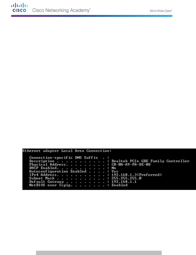
Before you analyze the MAC address on PC-A, look at an example from a different PC NIC. You can issue the ipconfig /all command to view the MAC address of your NICs. An example screen output is shown below. When using the ipconfig /all command, notice that MAC addresses are referred to as physical addresses. Reading the MAC address from left to right, the first six hex digits refer to the vendor (manufacturer) of this device. These first six hex digits (3 bytes) are also known as the organizationally unique identifier (OUI). This 3-byte code is assigned to the vendor by the IEEE organization. To find the manufacturer, you can use a tool such as www.macvendorlookup.com or go to the IEEE web site to find the registered OUI vendor codes. The IEEE web site address for OUI information is http://standards.ieee.org/develop/regauth/oui/public.html. The last six digits are the NIC serial number assigned by the manufacturer.
a. Using the output from the ipconfig /all command, answer the following questions.
What is the OUI portion of the MAC address for this device?
___________________________________
What is the serial number portion of the MAC address for this device?
____________________________
Using the example above, find the name of the vendor that manufactured this NIC.
__________________
b.From the command prompt on PC-A, issue the ipconfig /all command and identify the OUI portion of the MAC address for the NIC of PC-A.
__________________________________________________________________________
______
Identify the serial number portion of the MAC address for the NIC of PC-A.
________________________
Identify the name of the vendor that manufactured the NIC of PC-A.
_____________________________
©2013 Cisco and/or its affiliates. All rights reserved. This document is Cisco Public.
Page 82 of 257

Step 2: Analyze the MAC address for the R1 G0/1 interface.
You can use a variety of commands to display MAC addresses on the router.
a.Console into R1 and use the show interfaces g0/1 command to find the MAC address information. A sample is shown below. Use output generated by your router to answer the questions.
R1> show interfaces g0/1
GigabitEthernet0/1 is up, line protocol is up
Hardware is CN Gigabit Ethernet, address is 30f7.0da3.1821 (bia 30f7.0da3.1821)
Internet address is 192.168.1.1/24
MTU 1500 bytes, BW 100000 Kbit/sec, DLY 100 usec, reliability 255/255, txload 1/255, rxload 1/255
Encapsulation ARPA, loopback not set Keepalive set (10 sec)
Full Duplex, 100Mbps, media type is RJ45
output flow-control is unsupported, input flow-control is unsupported ARP type: ARPA, ARP Timeout 04:00:00
Last input 00:00:00, output 00:00:00, output hang never Last clearing of "show interface" counters never
Input queue: 0/75/0/0 (size/max/drops/flushes); Total output drops: 0 Queueing strategy: fifo
Output queue: 0/40 (size/max)
5 minute input rate 3000 bits/sec, 4 packets/sec
5 minute output rate 0 bits/sec, 0 packets/sec
15183 packets input, 971564 bytes, 0 no buffer Received 13559 broadcasts (0 IP multicasts)
0 runts, 0 giants, 0 throttles
0 input errors, 0 CRC, 0 frame, 0 overrun, 0 ignored 0 watchdog, 301 multicast, 0 pause input
1396 packets output, 126546 bytes, 0 underruns
0 output errors, 0 collisions, 1 interface resets
195 unknown protocol drops
0 babbles, 0 late collision, 0 deferred
0 lost carrier, 0 no carrier, 0 pause output
0 output buffer failures, 0 output buffers swapped out
What is the MAC address for G0/1 on R1?
_________________________________________________
What is the MAC serial number for G0/1?
__________________________________________________
What is the OUI for G0/1?
______________________________________________________________
Based on this OUI, what is the name of the vendor?
__________________________________________
What does bia stand for?
_______________________________________________________________
Why does the output show the same MAC address twice?
__________________________________________________________________________
__________
© 2013 Cisco and/or its affiliates. All rights reserved. This document is Cisco Public. Page 83 of 257
b.Another way to display the MAC addresses on the router is to use the show arp command. Use the show arp command to display MAC address information. This command maps the Layer 2 address to its corresponding Layer 3 address. A sample is shown below. Use output generated by your router to answer the questions.
R1> show |
arp |
|
|
|
|
Protocol |
Address |
Age (min) |
Hardware Addr |
Type |
Interface |
Internet |
192.168.1.1 |
- |
30f7.0da3.1821 |
ARPA |
|
GigabitEthernet0/1 |
|
|
|
|
|
Internet |
192.168.1.3 |
0 |
c80a.a9fa.de0d |
ARPA |
|
GigabitEthernet0/1 |
|
|
|
|
|
What Layer 2 addresses are displayed on R1?
__________________________________________________________________________
__________
What Layer 3 addresses are displayed on R1?
__________________________________________________________________________
__________
Why do you think there is no information showing for the switch with the show arp command?
__________________________________________________________________________
__________
Step 3: View the MAC addresses on the switch.
a.Console into the switch and use the show interfaces command for ports 5 and 6 to display MAC address information. A sample is shown below. Use output generated by your switch to answer the questions.
Switch> show interfaces f0/5
FastEthernet0/5 is up, line protocol is up (connected)
Hardware is Fast Ethernet, address is 0cd9.96e8.7285 (bia 0cd9.96e8.7285) MTU 1500 bytes, BW 100000 Kbit, DLY 100 usec,
reliability 255/255, txload 1/255, rxload 1/255 Encapsulation ARPA, loopback not set
Keepalive set (10 sec)
Full-duplex, 100Mb/s, media type is 10/100BaseTX
input flow-control is off, output flow-control is unsupported ARP type: ARPA, ARP Timeout 04:00:00
Last input 00:00:45, output 00:00:00, output hang never Last clearing of "show interface" counters never
Input queue: 0/75/0/0 (size/max/drops/flushes); Total output drops: 0 Queueing strategy: fifo
Output queue: 0/40 (size/max)
5 minute input rate 0 bits/sec, 0 packets/sec
5 minute output rate 0 bits/sec, 0 packets/sec
3362 packets input, 302915 bytes, 0 no buffer Received 265 broadcasts (241 multicasts)
0 runts, 0 giants, 0 throttles
0 input errors, 0 CRC, 0 frame, 0 overrun, 0 ignored 0 watchdog, 241 multicast, 0 pause input
0 input packets with dribble condition detected
38967 packets output, 2657748 bytes, 0 underruns
0 output errors, 0 collisions, 1 interface resets
© 2013 Cisco and/or its affiliates. All rights reserved. This document is Cisco Public. Page 84 of 257
0 babbles, 0 late collision, 0 deferred
0 lost carrier, 0 no carrier, 0 PAUSE output
0 output buffer failures, 0 output buffers swapped out
What is the MAC address for F0/5 on your switch?
___________________________________________
Issue the same command and write down the MAC address for F0/6.
____________________________
Are the OUIs shown on the switch the same as those that were displayed on the router?
_____________
The switch keeps track of devices by their Layer 2 MAC addresses. In our topology, the switch has knowledge of both MAC address of R1 and the MAC address of PC-A.
b.Issue the show mac address-table command on the switch. A sample is shown below. Use output generated by your switch to answer the questions.
Switch> show mac address-table
Mac Address Table
-------------------------------------------
Vlan |
Mac Address |
Type |
Ports |
---- |
----------- |
-------- |
----- |
All |
0100.0ccc.cccc |
STATIC |
CPU |
All |
0100.0ccc.cccd |
STATIC |
CPU |
All |
0180.c200.0000 |
STATIC |
CPU |
All |
0180.c200.0001 |
STATIC |
CPU |
All |
0180.c200.0002 |
STATIC |
CPU |
All |
0180.c200.0003 |
STATIC |
CPU |
All |
0180.c200.0004 |
STATIC |
CPU |
All |
0180.c200.0005 |
STATIC |
CPU |
All |
0180.c200.0006 |
STATIC |
CPU |
All |
0180.c200.0007 |
STATIC |
CPU |
All |
0180.c200.0008 |
STATIC |
CPU |
All |
0180.c200.0009 |
STATIC |
CPU |
All |
0180.c200.000a |
STATIC |
CPU |
All |
0180.c200.000b |
STATIC |
CPU |
All |
0180.c200.000c |
STATIC |
CPU |
All |
0180.c200.000d |
STATIC |
CPU |
All |
0180.c200.000e |
STATIC |
CPU |
All |
0180.c200.000f |
STATIC |
CPU |
All |
0180.c200.0010 |
STATIC |
CPU |
All |
ffff.ffff.ffff |
STATIC |
CPU |
|
|
|
|
1 |
30f7.0da3.1821 |
DYNAMIC |
Fa0/5 |
|
|
|
|
1 |
c80a.a9fa.de0d |
DYNAMIC |
Fa0/6 |
Total Mac Addresses for this criterion: 22
Did the switch display the MAC address of PC-A? If you answered yes, what port was it on?
__________________________________________________________________________
__________
Did the switch display the MAC address of R1? If you answered yes, what port was it on?
__________________________________________________________________________
__________
© 2013 Cisco and/or its affiliates. All rights reserved. This document is Cisco Public. Page 85 of 257
Reflection
1.Can you have broadcasts at the Layer 2 level? If so, what would the MAC address be?
_____________________________________________________________________________
__________
_____________________________________________________________________________
__________
2.Why would you need to know the MAC address of a device?
_____________________________________________________________________________
__________
_____________________________________________________________________________
__________
Router Interface Summary Table
Router Interface Summary
Router Model |
Ethernet Interface #1 |
Ethernet Interface #2 |
Serial Interface #1 |
Serial Interface #2 |
|
|
|
|
|
1800 |
Fast Ethernet 0/0 |
Fast Ethernet 0/1 |
Serial 0/0/0 (S0/0/0) |
Serial 0/0/1 (S0/0/1) |
|
(F0/0) |
(F0/1) |
|
|
|
|
|
|
|
1900 |
Gigabit Ethernet 0/0 |
Gigabit Ethernet 0/1 |
Serial 0/0/0 (S0/0/0) |
Serial 0/0/1 (S0/0/1) |
|
(G0/0) |
(G0/1) |
|
|
|
|
|
|
|
2801 |
Fast Ethernet 0/0 |
Fast Ethernet 0/1 |
Serial 0/1/0 (S0/1/0) |
Serial 0/1/1 (S0/1/1) |
|
(F0/0) |
(F0/1) |
|
|
|
|
|
|
|
2811 |
Fast Ethernet 0/0 |
Fast Ethernet 0/1 |
Serial 0/0/0 (S0/0/0) |
Serial 0/0/1 (S0/0/1) |
|
(F0/0) |
(F0/1) |
|
|
|
|
|
|
|
2900 |
Gigabit Ethernet 0/0 |
Gigabit Ethernet 0/1 |
Serial 0/0/0 (S0/0/0) |
Serial 0/0/1 (S0/0/1) |
|
(G0/0) |
(G0/1) |
|
|
|
|
|
|
|
Note: To find out how the router is configured, look at the interfaces to identify the type of router and how many interfaces the router has. There is no way to effectively list all the combinations of configurations for each router class. This table includes identifiers for the possible combinations of Ethernet and Serial interfaces in the device. The table does not include any other type of interface, even though a specific router may contain one. An example of this might be an ISDN BRI interface. The string in parenthesis is the legal abbreviation that can be used in Cisco IOS commands to represent the interface.
© 2013 Cisco and/or its affiliates. All rights reserved. This document is Cisco Public. Page 86 of 257
Lab 10 – Using Wireshark to Examine Ethernet Frames
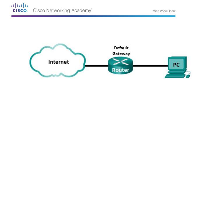
Topology
Objectives
Part 1: Examine the Header Fields in an Ethernet II Frame
Part 2: Use Wireshark to Capture and Analyze Ethernet Frames
Background / Scenario
When upper layer protocols communicate with each other, data flows down the Open Systems Interconnection (OSI) layers and is encapsulated into a Layer 2 frame. The frame composition is dependent on the media access type. For example, if the upper layer protocols are TCP and IP and the media access is Ethernet, then the Layer 2 frame encapsulation will be Ethernet II. This is typical for a LAN environment.
When learning about Layer 2 concepts, it is helpful to analyze frame header information. In the first part of this lab, you will review the fields contained in an Ethernet II frame. In Part 2, you will use Wireshark to capture and analyze Ethernet II frame header fields for local and remote traffic.
Required Resources
1 PC (Windows 7, Vista, or XP with Internet access with Wireshark installed)
Part 4: Examine the Header Fields in an Ethernet II Frame
In Part 1, you will examine the header fields and content in an Ethernet II Frame. A Wireshark capture will be used to examine the contents in those fields.
Step 1: Review the Ethernet II header field descriptions and lengths.
|
Destination |
Source |
Frame |
|
|
Preamble |
Address |
Address |
Type |
Data |
FCS |
|
|
|
|
|
|
8 Bytes |
6 Bytes |
6 Bytes |
2 Bytes |
46 – 1500 Bytes |
4 Bytes |
|
|
|
|
|
|
Step 2: Examine the network configuration of the PC.
This PC host IP address is 10.20.164.22 and the default gateway has an IP address of 10.20.164.17.
© 2013 Cisco and/or its affiliates. All rights reserved. This document is Cisco Public. Page 87 of 257
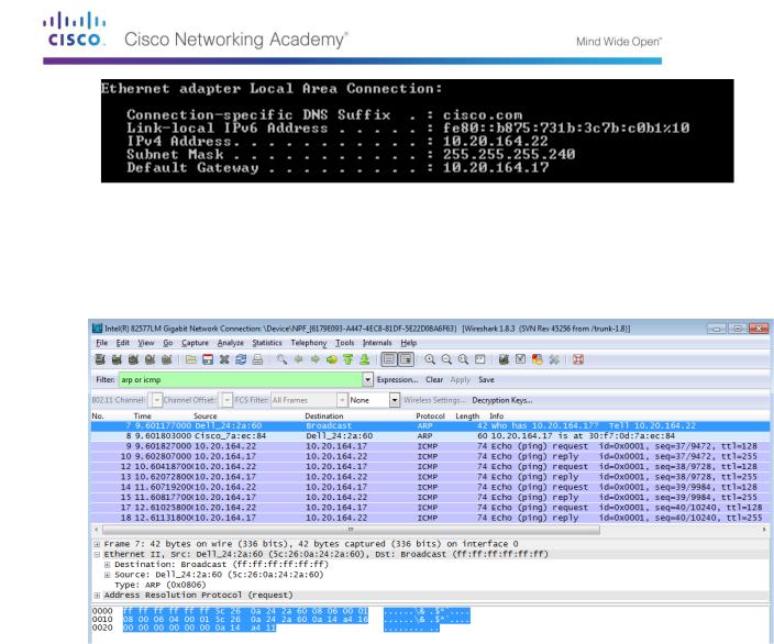
Step 3: Examine Ethernet frames in a Wireshark capture.
The Wireshark capture below shows the packets generated by a ping being issued from a PC host to its default gateway. A filter has been applied to Wireshark to view the ARP and ICMP protocols only. The session begins with an ARP query for the MAC address of the gateway router, followed by four ping requests and replies.
Step 4: Examine the Ethernet II header contents of an ARP request.
The following table takes the first frame in the Wireshark capture and displays the data in the Ethernet II header fields.
© 2013 Cisco and/or its affiliates. All rights reserved. This document is Cisco Public. Page 88 of 257

Field |
|
Value |
|
|
Description |
|
|
|
|
|
|
Preamble |
|
Not shown in capture |
|
This field contains synchronizing bits, processed by |
|
|
|
|
|
the NIC hardware. |
|
|
|
|
|
|
|
Destination |
|
Broadcast |
|
Layer 2 addresses for the frame. Each address is |
|
Address |
|
(ff:ff:ff:ff:ff:ff) |
|
48 bits long, or 6 octets, expressed as 12 |
|
|
|
|
|
hexadecimal digits, 0-9,A-F. |
|
Source Address |
|
Dell_24:2a:60 |
|
||
|
|
A common format is 12:34:56:78:9A:BC. |
|||
|
|
(5c:26:0a:24:2a:60) |
|
||
|
|
|
The first six hex numbers indicate the manufacturer |
||
|
|
|
|
||
|
|
|
|
of the network interface card (NIC), the last six hex |
|
|
|
|
|
numbers are the serial number of the NIC. |
|
|
|
|
|
The destination address may be a broadcast, which |
|
|
|
|
|
contains all ones, or a unicast. The source address |
|
|
|
|
|
is always unicast. |
|
|
|
|
|
|
|
Frame Type |
|
0x0806 |
|
For Ethernet II frames, this field contains a |
|
|
|
|
|
hexadecimal value that is used to indicate the type |
|
|
|
|
|
of upper-layer protocol in the data field. There are |
|
|
|
|
|
numerous upper-layer protocols supported by |
|
|
|
|
|
Ethernet II. Two common frame types are: |
|
|
|
|
|
Value |
Description |
|
|
|
|
0x0800 |
IPv4 Protocol |
|
|
|
|
0x0806 Address resolution protocol (ARP) |
|
|
|
|
|
|
|
Data |
|
ARP |
|
Contains the encapsulated upper-level protocol. |
|
|
|
|
|
The data field is between 46 – 1,500 bytes. |
|
|
|
|
|
|
|
FCS |
|
Not shown in capture |
|
Frame Check Sequence, used by the NIC to |
|
|
|
|
|
identify errors during transmission. The value is |
|
|
|
|
|
computed by the sending machine, encompassing |
|
|
|
|
|
frame addresses, type, and data field. It is verified |
|
|
|
|
|
by the receiver. |
|
|
|
|
|
|
|
What is significant about the contents of the destination address field?
_____________________________________________________________________________
__________
_____________________________________________________________________________
__________
Why does the PC send out a broadcast ARP prior to sending the first ping request?
_____________________________________________________________________________
__________
_____________________________________________________________________________
__________
_____________________________________________________________________________
__________
What is the MAC address of the source in the first frame? _______________________
What is the Vendor ID (OUI) of the Source’s NIC? __________________________
What portion of the MAC address is the OUI?
_____________________________________________________________________________
__________
What is the Source’s NIC serial number? _________________________________
© 2013 Cisco and/or its affiliates. All rights reserved. This document is Cisco Public. Page 89 of 257
Part 5: Use Wireshark to Capture and Analyze Ethernet Frames
In Part 2, you will use Wireshark to capture local and remote Ethernet frames. You will then examine the information that is contained in the frame header fields.
Step 1: Determine the IP address of the default gateway on your PC.
Open a command prompt window and issue the ipconfig command.
What is the IP Address of the PC Default Gateway? ________________________
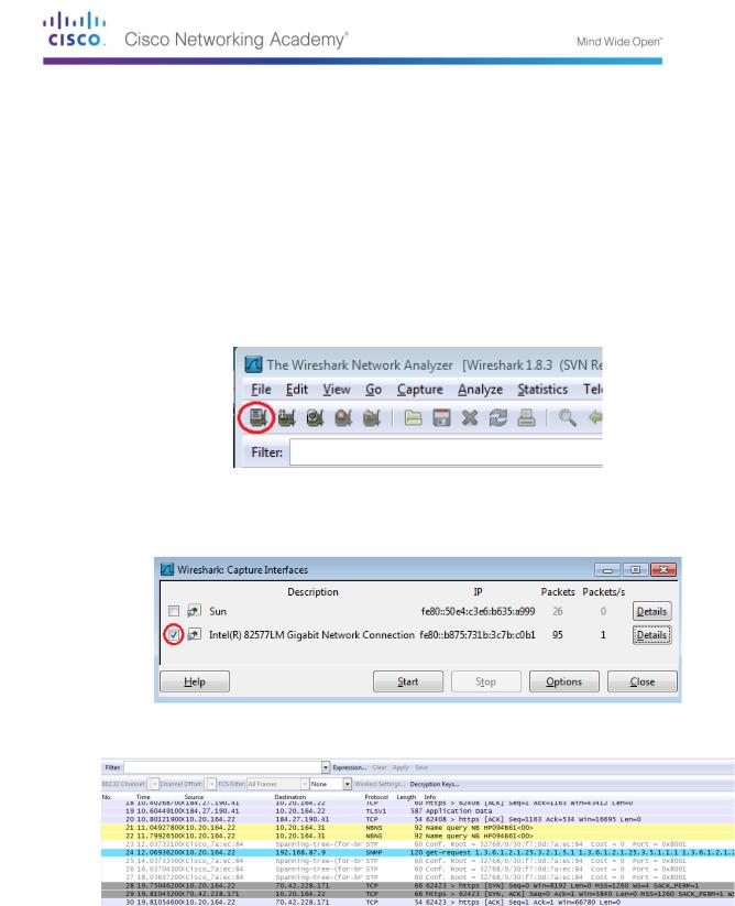
Step 2: Start capturing traffic on your PC’s NIC.
a.Open Wireshark.
b.On the Wireshark Network Analyzer toolbar, click the Interface List icon.
c.On the Wireshark: Capture Interfaces window, select the interface to start traffic capturing by clicking the appropriate check box, and then click Start. If you are uncertain of what interface to check, click Details for more information about each interface listed.
d. Observe the traffic that appears in the Packet List window.
Step 3: Filter Wireshark to display only ICMP traffic.
You can use the filter in Wireshark to block visibility of unwanted traffic. The filter does not block the capture of unwanted data; it only filters what to display on the screen. For now, only ICMP traffic is to be displayed.
In the Wireshark Filter box, type icmp. The box should turn green if you typed the filter correctly. If the box is green, click Apply to apply the filter.
© 2013 Cisco and/or its affiliates. All rights reserved. This document is Cisco Public. Page 90 of 257