

CCNA_R&S-Student_Lab_Manual
.pdfID |
Manufacturer |
Model |
Type |
Functionality |
|
Physical Characteristics |
|
|
|
|
|
|
|
|
|
|
|
|
2 |
GigabitEthernet Ports |
|
|
|
|
|
2 |
EHWIC slots |
1 |
Cisco |
1941 |
Router |
Router |
2 CompactFlash slots |
|
|
|
|
|
|
1 |
ISM slot |
|
|
|
|
|
2 |
Console ports: USB, RJ-45 |
|
|
|
|
|
|
|
2 |
|
|
|
|
|
|
|
|
|
|
|
|
|
3 |
|
|
|
|
|
|
|
|
|
|
|
|
|
4 |
|
|
|
|
|
|
|
|
|
|
|
|
|
5 |
|
|
|
|
|
|
|
|
|
|
|
|
|
6 |
|
|
|
|
|
|
|
|
|
|
|
|
|
Part 22: Identify Network Media
Your instructor will provide various network media for identification. You will name the network media, identify the media type (copper, fiber optic, or wireless), and provide a short media description including what device types it connects. Use the table below to record your findings. The first line in the table has been filled out as a reference.
© 2013 Cisco and/or its affiliates. All rights reserved. This document is Cisco Public. Page 61 of 257
ID |
Network Media |
Type |
Description and to What It Connects |
|
|
|
|
|
|
|
Connect wired NIC and Ethernet ports on network devices |
1 |
UTP |
Copper |
Cat 5 straight-through wired. Connects PCs and routers to |
|
|
|
switches and wiring panels. |
|
|
|
|
2 |
|
|
|
|
|
|
|
3 |
|
|
|
|
|
|
|
4 |
|
|
|
|
|
|
|
5 |
|
|
|
|
|
|
|
6 |
|
|
|
|
|
|
|
Reflection
After you have identified the network equipment, where would you find more information about the equipment?
_____________________________________________________________________________
__________
_____________________________________________________________________________
__________
_____________________________________________________________________________
__________
© 2013 Cisco and/or its affiliates. All rights reserved. This document is Cisco Public. Page 62 of 257
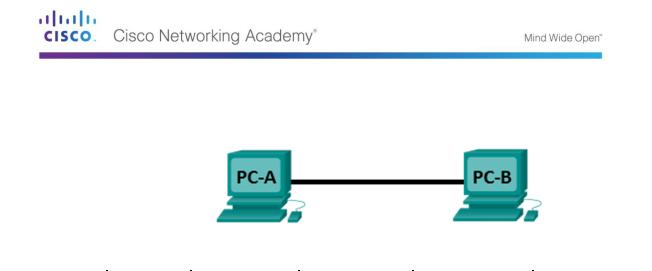
Lab 7 - Building an Ethernet Crossover Cable
Topology
Addressing Table
Device |
Interface |
IP Address |
Subnet Mask |
Default Gateway |
|
|
|
|
|
PC-A |
NIC |
192.168.10.1 |
255.255.255.0 |
N/A |
|
|
|
|
|
PC-B |
NIC |
192.168.10.2 |
255.255.255.0 |
N/A |
|
|
|
|
|
Objectives
Part 1: Analyze Ethernet Cabling Standards and Pinouts
Analyze diagrams and tables for the TIA/EIA 568-A standard Ethernet cable.
Analyze diagrams and tables for the TIA/EIA 568-B standard Ethernet cable.
Part 2: Build an Ethernet Crossover Cable
Build and terminate a TIA/EIA 568-A cable end.
Build and terminate a TIA/EIA 568-B cable end.
Part 3: Test an Ethernet Crossover Cable
Test an Ethernet crossover cable with a cable tester.
Connect two PCs together using an Ethernet crossover cable.
Background / Scenario
In this lab, you will build and terminate an Ethernet crossover cable and test it by connecting two PCs together and pinging between them. You will first analyze the Telecommunications Industry Association/Electronic Industries Association (TIA/EIA) 568-A and 568-B standards and how they apply to Ethernet cables. You will then construct an Ethernet crossover cable and test it. Finally, you will use the cable you just constructed to connect two PCs together and test it by pinging between them.
Note: With autosensing capabilities available on many devices, such as the Cisco 1941 Integrated Services Router (ISR) switch, you may see straight-through cables connecting like devices.
Required Resources
One length of cable, either Category 5 or 5e. Cable length should be 0.6 to 0.9m (2 to 3 ft.)
2 RJ-45 connectors
RJ-45 crimping tool
Wire cutter
Wire stripper
Ethernet cable tester (optional)
©2013 Cisco and/or its affiliates. All rights reserved. This document is Cisco Public.
Page 63 of 257

2 PCs (Windows 7, Vista, or XP)
Part 23: Analyze Ethernet Cabling Standards and Pinouts
The TIA/EIA has specified unshielded twisted pair (UTP) cabling standards for use in LAN cabling environments. TIA/EIA 568-A and 568-B stipulates the commercial cabling standards for LAN installations; these are the standards most commonly used in LAN cabling for organizations and they determine which color wire is used on each pin.
With a crossover cable, the second and third pairs on the RJ-45 connector at one end of the cable are reversed at the other end, which reverses the send and receive pairs. The cable pinouts are the 568-A standard on one end and the 568-B standard on the other end. Crossover cables are normally used to connect hubs to hubs or switches to switches, but they can also be used to directly connect two hosts to create a simple network.
Note: With modern networking devices, a straight-through cable can often be used even when connecting like devices because of their autosensing feature. With autosensing, the interfaces detect whether the send and receive circuit pairs are correctly connected. If they are not, the interfaces reverse one end of the connection. Autosensing also alters the speed of the interfaces to match the slowest one. For example, if connecting a Gigabit Ethernet (1000 Mb/s) router interface to a Fast Ethernet (100 Mb/s) switch interface, the connection uses Fast Ethernet.
The Cisco 2960 switch has autosensing turned on, by default; therefore, connecting two 2960 switches together works with either a crossover or a straight-through cable. With some older switches, this is not the case and a crossover cable must be used.
In addition, the Cisco 1941 router Gigabit Ethernet interfaces are autosensing and a straightthrough cable may be used to connect a PC directly to the router interface (bypassing the switch). With some older routers, this is not the case and a crossover cable must be used.
When directly connecting two hosts, it is generally advisable to use a crossover cable.
Step 1: Analyze diagrams and tables for the TIA/EIA 568-A standard Ethernet cable.
The following table and diagrams display the color scheme and pinouts, as well as the function of the four pairs of wires used for the 568-A standard.
Note: In LAN installations using 100Base-T (100 Mb/s), only two pairs out of the four are used.
568-A 10/100/1000Base-TX Ethernet
|
|
|
10Base-T Signal |
1000Base-T |
Pin Number |
Pair Number |
Wire Color |
100Base-TX Signal |
Signal |
|
|
|
|
|
1 |
2 |
White/Green |
Transmit |
BI_DA+ |
|
|
|
|
|
2 |
2 |
Green |
Transmit |
BI_DA- |
|
|
|
|
|
3 |
3 |
White/Orange |
Receive |
BI_DB+ |
|
|
|
|
|
4 |
1 |
Blue |
Not Used |
BI_DC+ |
|
|
|
|
|
5 |
1 |
White/Blue |
Not Used |
BI_DC- |
|
|
|
|
|
6 |
3 |
Orange |
Receive |
BI_DB- |
|
|
|
|
|
7 |
4 |
White/Brown |
Not Used |
BI_DD+ |
|
|
|
|
|
8 |
4 |
Brown |
Not Used |
BI_DD- |
|
|
|
|
|
The following diagrams display how the wire color and pinouts align with an RJ-45 jack for the 568-A standard.
© 2013 Cisco and/or its affiliates. All rights reserved. This document is Cisco Public. Page 64 of 257
Step 2: Analyze diagrams and tables for the TIA/EIA 568-B standard Ethernet cable.
The following table and diagram display the color scheme and pinouts for the 568-B standard.
© 2013 Cisco and/or its affiliates. All rights reserved. This document is Cisco Public. Page 65 of 257
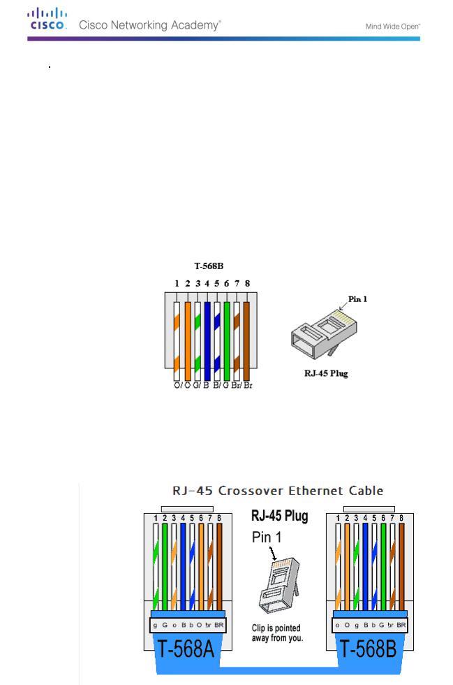
568-B 10/100/1000-BaseTX Ethernet
|
|
|
10Base-T Signal |
1000Base-T |
Pin Number |
Pair Number |
Wire Color |
100Base-TX Signal |
Signal |
|
|
|
|
|
1 |
2 |
White/Orange |
Transmit |
BI_DA+ |
|
|
|
|
|
2 |
2 |
Orange |
Transmit |
BI_DA- |
|
|
|
|
|
3 |
3 |
White/Green |
Receive |
BI_DB+ |
|
|
|
|
|
4 |
1 |
Blue |
Not Used |
BI_DC+ |
|
|
|
|
|
5 |
1 |
White/Blue |
Not Used |
BI_DC- |
|
|
|
|
|
6 |
3 |
Green |
Receive |
BI_DB- |
|
|
|
|
|
7 |
4 |
White/Brown |
Not Used |
BI_DD+ |
|
|
|
|
|
8 |
4 |
Brown |
Not Used |
BI_DD- |
|
|
|
|
|
Part 24: Build an Ethernet Crossover Cable
A crossover cable has the second and third pairs on the RJ-45 connector at one end, reversed at the other end (refer to the table in Part 1, Step 2). The cable pinouts are the 568-A standard on one end and the 568-B standard on the other end. The two following diagrams illustrate this concept.
© 2013 Cisco and/or its affiliates. All rights reserved. This document is Cisco Public. Page 66 of 257
Step 1: Build and terminate a TIA/EIA 568-A cable end.
a.Determine the cable length required. (Your instructor will let you know the cable length you should make.)
Note: If you were making a cable in a production environment, the general guideline is to add another 12 in. (30.48 cm) to the length.
b.Cut off a piece of cable to the desired length and using your wire stripper, remove 5.08 cm (2 in.) of the cable jacket from both ends.
c.Hold the four pairs of twisted cables tightly where the jacket was cut away. Reorganize the cable pairs into the order of the 568-A wiring standard. Refer to the diagrams, if necessary. Take as much care as possible to maintain the twists in the cable; this provides noise cancellation.
d.Flatten, straighten, and line up the wires using your thumb and forefinger.
e.Ensure that the cable wires are still in the correct order for the 568-A standard. Using your wire cutters, trim the four pairs in a straight line to within 1.25 to 1.9 cm (1/2 to 3/4 in.).
f.Place an RJ-45 connector on the end of your cable, with the prong on the underside pointing downward. Firmly insert the wires into the RJ-45 connector. All wires should be seen at the end of the connector in their proper positions. If the wires are not extending to the end of the connector, take the cable out, rearrange the wires as necessary, and reinsert the wires back into the RJ-45 connector.
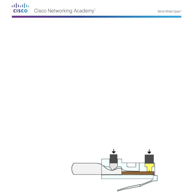
g.If everything is correct, insert the RJ-45 connector with cable into the crimper. Crimp down hard enough to force the contacts on the RJ-45 connector through the insulation on the wires, thus completing the conducting path. See the following diagram for an example.
Step 2: Build and terminate a TIA/EIA 568-B cable end.
Repeat steps 1a to 1g using the 568-B color wiring scheme for the other end.
Part 25: Test an Ethernet Crossover Cable
Step 1: Test the cable.
Many cable testers will test for length and mapping of wires. If the cable tester has a wire map feature, it verifies which pins on one end of the cable are connected to which pins on the other end.
If your instructor has a cable tester, test the crossover cable for functionality. If it fails, check with your instructor first as to whether you should re-cable the ends and re-test.
Step 2: Connect two PCs together via NICs using your Ethernet crossover cable.
a.Working with a lab partner, set your PC to one of the IP addresses shown in the Addressing Table (see page 1). For example, if your PC is PC-A, your IP address should be set to
192.168.10.1 with a 24-bit subnet mask. You partner’s IP address should be 192.168.10.2. The default gateway address can be left empty.
©2013 Cisco and/or its affiliates. All rights reserved. This document is Cisco Public.
Page 67 of 257
b.Using the crossover cable you made, connect the two PCs together via their NICs.
c.On the PC-A command prompt, ping the PC-B IP address.
Note: The Windows firewall may have to be temporarily disabled for pings to be successful. If the firewall is disabled, make sure you re-enable it at the conclusion of this lab.
d. Repeat the process and ping from PC-B to PC-A.
Assuming IP addressing and firewall are not issues, your pings should be successful if the cables were properly made.
Reflection
1.Which part of making cables did you find the most difficult?
_____________________________________________________________________________
__________
2.Why do you have to learn how to make a cable if you can easily buy pre-made cables?
_____________________________________________________________________________
__________
© 2013 Cisco and/or its affiliates. All rights reserved. This document is Cisco Public. Page 68 of 257
Lab 8 – Viewing Wireless and Wired NIC Information
Objectives
Part 1: Identify and Work with PC NICs
Part 2: Identify and Use the System Tray Network Icons
Background / Scenario
This lab requires you to determine the availability and status of the network interface cards (NICs) on the PC that you use. Windows provides a number of ways to view and work with your NICs.
In this lab, you will access the NIC information of your PC and change the status of these cards.
Required Resources
1 PC (Windows 7, Vista, or XP with two NICs, wired and wireless, and a wireless connection)
Note: At the start of this lab, the wired Ethernet NIC in the PC was cabled to one of the integrated switch ports on a wireless router and the Local Area Connection (wired) was enabled. The wireless NIC was disabled initially. If the wired and wireless NICs are both enabled the PC will receive two different IP addresses and the wireless NIC will take precedence.
Part 26: Identify and Work with PC NICs
In Part 1, you will identify the NIC types in the PC that you are using. You will explore different ways to extract information about these NICs and how to activate and deactivate them.
Note: This lab was performed using a PC running on the Windows 7 operating system. You should be able to perform the lab with one of the other Windows operating systems listed; however, menu selections and screens may vary.
Step 1: Use the Network and Sharing Center.
a.Open the Network and Sharing Center by clicking the Windows Start button > Control Panel > View network status and tasks under Network and Internet heading in the Category View.
b.In the left pane, click the Change adapter settings link.
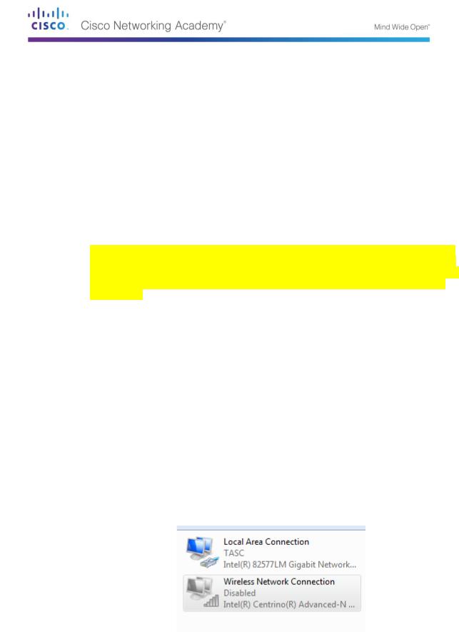
c.The Network Connections window displays, which provides the list of NICs available on this PC. Look for your Local Area Connection and Wireless Network Connection adapters in this window.
Note: Virtual Private Network (VPN) adapters and other types of network connections may also be displayed in this window.
© 2013 Cisco and/or its affiliates. All rights reserved. This document is Cisco Public. Page 69 of 257
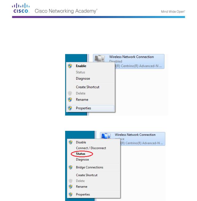
Step 2: Work with your wireless NIC.
a.Select the Wireless Network Connection option and right-click it to bring up a drop-down list. If your wireless NIC is disabled, you will have an option to Enable it. If your NIC was already enabled, then Disable would be the first option on this drop-down menu. If your
Wireless Network Connection is currently disabled, then click Enable.
b. Right-click the Wireless Network Connection, and then click Status.
c.The Wireless Network Connection Status window displays where you can view information about your wireless connection.
© 2013 Cisco and/or its affiliates. All rights reserved. This document is Cisco Public. Page 70 of 257