

CCNA_R&S-Student_Lab_Manual
.pdfConfigure the IP address, subnet mask, and default gateway settings on PC-B.
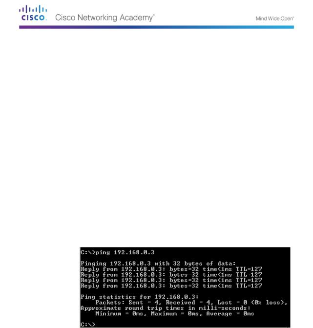
Ping PC-B from a command prompt window on PC-A.
Step 2: Configure the router.
Console into the router and enable privileged EXEC mode.
Router> enable
Router#
Enter configuration mode.
Router# conf t
Enter configuration commands, one per line. End with CNTL/Z.
Router(config)#
© 2013 Cisco and/or its affiliates. All rights reserved. This document is Cisco Public. Page 131 of 257

Assign a device name to the router.
Router(config)# hostname R1
Disable DNS lookup to prevent the router from attempting to translate incorrectly entered commands as though they were host names.
R1(config)# no ip domain-lookup
Assign class as the privileged EXEC encrypted password.
R1(config)# enable secret class
Assign cisco as the console password and enable login.
R1(config)# line con 0
R1(config-line)# password cisco
R1(config-line)# login
R1(config-line)# exit
R1(config)#
Assign cisco as the vty password and enable login.
R1(config)# line vty 0 4
R1(config-line)# password cisco
R1(config-line)# login
R1(config-line)# exit
R1(config)#
Encrypt the clear text passwords.
R1(config)# service password-encryption
Create a banner that warns anyone accessing the device that unauthorized access is prohibited.
R1(config)# banner motd #
Enter TEXT message. End with the character '#'.
Unauthorized access prohibited!
#
R1(config)#
Configure and activate both interfaces on the router.
R1(config)# int g0/0
R1(config-if)# description Connection to PC-B. R1(config-if)# ip address 192.168.0.1 255.255.255.0
R1(config-if)# no shut R1(config-if)#
*Nov 29 23:49:44.195: %LINK-3-UPDOWN: Interface GigabitEthernet0/0, changed state to down
*Nov 29 23:49:47.863: %LINK-3-UPDOWN: Interface GigabitEthernet0/0, changed state to up
*Nov 29 23:49:48.863: %LINEPROTO-5-UPDOWN: Line protocol on Interface GigabitEthernet0/0, changed state to up
R1(config-if)# int g0/1
R1(config-if)# description Connection to S1. R1(config-if)# ip address 192.168.1.1 255.255.255.0
R1(config-if)# no shut R1(config-if)# exit R1(config)# exit
© 2013 Cisco and/or its affiliates. All rights reserved. This document is Cisco Public. Page 132 of 257
*Nov 29 23:50:15.283: %LINK-3-UPDOWN: Interface GigabitEthernet0/1, changed state to down
*Nov 29 23:50:18.863: %LINK-3-UPDOWN: Interface GigabitEthernet0/1, changed state to up
*Nov 29 23:50:19.863: %LINEPROTO-5-UPDOWN: Line protocol on Interface GigabitEthernet0/1, changed state to up
R1#
Save the running configuration to the startup file.
R1# copy running-config startup-config
Destination filename [startup-config]? Building configuration...
[OK]
R1#
Set the clock on the router.
R1# clock set 17:00:00 29 Nov 2012
R1#
*Nov 29 17:00:00.000: %SYS-6-CLOCKUPDATE: System clock has been updated from 23:55:46 UTC Thu Nov 29 2012 to 17:00:00 UTC Thu Nov 29 2012, configured from console by console.
R1#
Note: Use the question mark (?) to help determine the correct sequence of the parameters needed to execute this command.
Ping PC-B from a command prompt window on PC-A.
Appendix B: Initializing and Reloading a Router and Switch
Part 40: Initialize the Router and Reload
Step 1: Connect to the router.
Console into the router and enter privileged EXEC mode using the enable command.
Router> enable
Router#
Step 2: Erase the startup configuration file from NVRAM.
Type the erase startup-config command to remove the startup configuration from nonvolatile random-access memory (NVRAM).
Router# erase startup-config
Erasing the nvram filesystem will remove all configuration files! Continue? [confirm]
© 2013 Cisco and/or its affiliates. All rights reserved. This document is Cisco Public. Page 133 of 257

[OK]
Erase of nvram: complete Router#
Step 3: Reload the router.
Issue the reload command to remove an old configuration from memory. When prompted to Proceed with reload, press Enter to confirm the reload. Pressing any other key will abort the reload.
Router# reload
Proceed with reload? [confirm]
*Nov 29 18:28:09.923: %SYS-5-RELOAD: Reload requested by console. Reload Reason: Reload Command.
Note: You may receive a prompt to save the running configuration prior to reloading the router. Respond by typing no and press Enter.
System configuration has been modified. Save? [yes/no]: no
Step 4: Bypass the initial configuration dialog.
After the router reloads, you are prompted to enter the initial configuration dialog. Enter no and press Enter.
Would you like to enter the initial configuration dialog? [yes/no]: no
Step 5: Terminate the autoinstall program.
You will be prompted to terminate the autoinstall program. Respond yes and then press Enter.
Would you like to terminate autoinstall? [yes]: yes
Router>
Part 12: Initialize the Switch and Reload
Step 6: Connect to the switch.
Console into the switch and enter privileged EXEC mode.
Switch> enable
Switch#
Step 7: Determine if there have been any virtual local-area networks (VLANs) created.
Use the show flash command to determine if any VLANs have been created on the switch.
Switch# show flash
Directory of flash:/
2 |
-rwx |
1919 |
Mar 1 1993 00:06:33 +00:00 |
private-config.text |
||
3 |
-rwx |
1632 |
Mar 1 1993 |
00:06:33 +00:00 |
config.text |
|
4 |
-rwx |
13336 |
Mar 1 1993 |
00:06:33 +00:00 |
multiple-fs |
|
5 |
-rwx |
11607161 |
Mar 1 1993 |
02:37:06 +00:00 |
c2960-lanbasek9- |
|
mz.150-2.SE.bin |
|
|
|
|
|
|
|
|
|
|
|
|
|
6 |
-rwx |
616 |
Mar 1 1993 |
00:07:13 +00:00 |
vlan.dat |
|
|
|
|
|
|
|
|
© 2013 Cisco and/or its affiliates. All rights reserved. This document is Cisco Public. Page 134 of 257

32514048 bytes total (20886528 bytes free) Switch#
Step 8: Delete the VLAN file.
If the vlan.dat file was found in flash, then delete this file.
Switch# delete vlan.dat
Delete filename [vlan.dat]?
You will be prompted to verify the file name. At this point, you can change the file name or just press Enter if you have entered the name correctly.
When you are prompted to delete this file, press Enter to confirm the deletion. (Pressing any other key will abort the deletion.)
Delete flash:/vlan.dat? [confirm]
Switch#
Step 9: Erase the startup configuration file.
Use the erase startup-config command to erase the startup configuration file from NVRAM. When you are prompted to remove the configuration file, press Enter to confirm the erase. (Pressing any other key will abort the operation.)
Switch# erase startup-config
Erasing the nvram filesystem will remove all configuration files! Continue? [confirm]
[OK]
Erase of nvram: complete Switch#
Step 10: Reload the switch.
Reload the switch to remove any old configuration information from memory. When you are prompted to reload the switch, press Enter to proceed with the reload. (Pressing any other key will abort the reload.)
Switch# reload
Proceed with reload? [confirm]
Note: You may receive a prompt to save the running configuration prior to reloading the switch. Type no and press Enter.
System configuration has been modified. Save? [yes/no]: no
Step 11: Bypass the initial configuration dialog.
After the switch reloads, you should see a prompt to enter the initial configuration dialog. Type no at the prompt and press Enter.
Would you like to enter the initial configuration dialog? [yes/no]: no Switch>
© 2013 Cisco and/or its affiliates. All rights reserved. This document is Cisco Public. Page 135 of 257
Lab 16 - Using Wireshark to Observe the TCP 3-Way Handshake
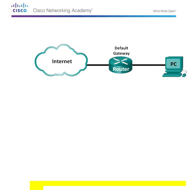
Topology
Objectives
Part 41: Part 1: Prepare Wireshark to Capture Packets
Select an appropriate NIC interface to capture packets.
Part 42: Part 2: Capture, Locate, and Examine Packets
Capture a web session to www.google.com. Locate appropriate packets for a web session.
Examine information within packets, including IP addresses, TCP port numbers, and TCP control flags.
Background / Scenario
In this lab, you will use Wireshark to capture and examine packets generated between the PC browser using the HyperText Transfer Protocol (HTTP) and a web server, such as www.google.com. When an application, such as HTTP or File Transfer Protocol (FTP) first starts on a host, TCP uses the three-way handshake to establish a reliable TCP session between the two hosts. For example, when a PC uses a web browser to surf the Internet, a three-way handshake is initiated and a session is established between the PC host and web server. A PC can have multiple, simultaneous, active TCP sessions with various web sites.
Note: This lab cannot be completed using Netlab. This lab assumes that you have Internet
access.
Required Resources
1 PC (Windows 7, Vista, or XP with a command prompt access, Internet access, and Wireshark installed)
Part 13: Prepare Wireshark to Capture Packets
In Part 1, you start the Wireshark program and select the appropriate interface to begin capturing packets.
Step 1: Retrieve the PC interface addresses.
For this lab, you need to retrieve your PC’s IP address and its network interface card (NIC) physical address, also called the MAC address.
Open a command prompt window, type ipconfig /all and then press Enter.
© 2013 Cisco and/or its affiliates. All rights reserved. This document is Cisco Public. Page 136 of 257
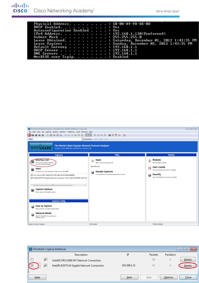
Write down the IP and MAC addresses associated with the selected Ethernet adapter, because that is the source address to look for when examining captured packets.
The PC host IP address:
________________________________________________________
The PC host MAC address:
_____________________________________________________
Step 2: Start Wireshark and select the appropriate interface.
Click the Windows Start button and on the pop-up menu, double-click Wireshark.
After Wireshark starts, click Interface List.
In the Wireshark: Capture Interfaces window, click the check the box next to the interface connected to your LAN.
© 2013 Cisco and/or its affiliates. All rights reserved. This document is Cisco Public. Page 137 of 257
Note: If multiple interfaces are listed and you are unsure which interface to check, click Details. Click the 802.3 (Ethernet) tab, and verify that the MAC address matches what you wrote down in Step 1b. Close the Interface Details window after verification.
Part 14: Capture, Locate, and Examine Packets
Step 3: Click the Start button to start the data capture.
Go to www.google.com. Minimize the Google window, and return to Wireshark. Stop the data capture. You should see captured traffic similar to that shown below in step b.
Note: Your instructor may provide you with a different website. If so, enter the website name or address here:
__________________________________________________________________________
__________
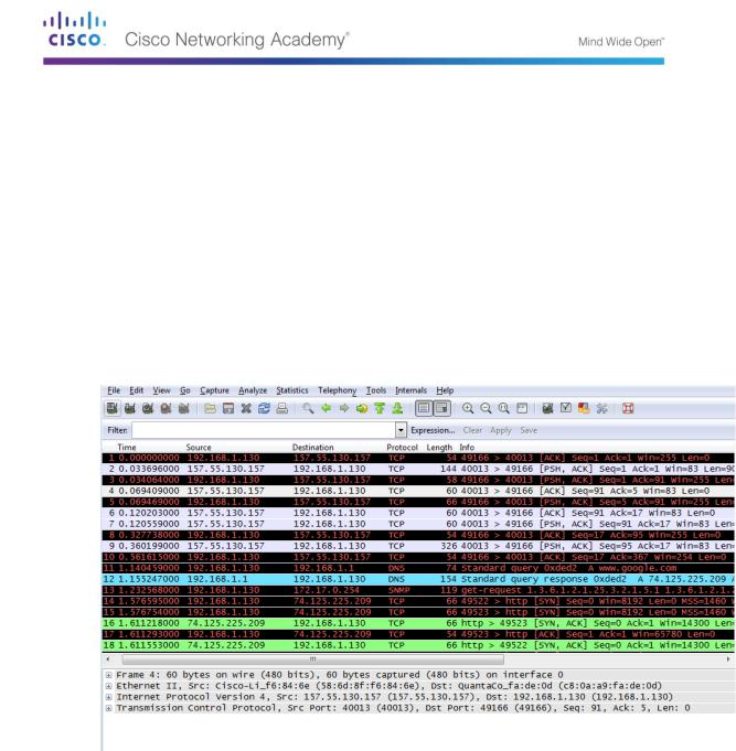
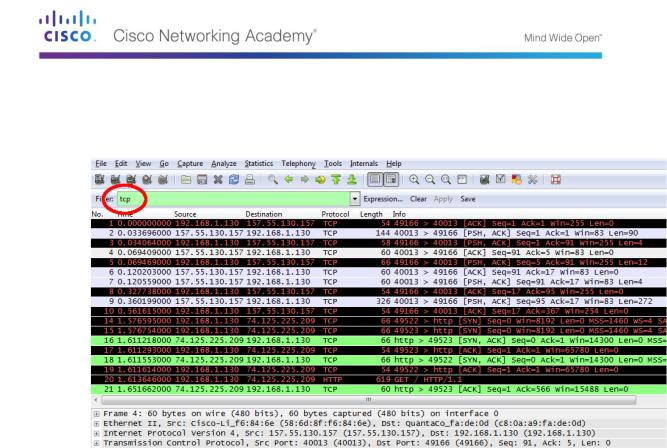
The capture window is now active. Locate the Source, Destination, and Protocol columns.
Step 4: Locate appropriate packets for the web session.
If the computer was recently started and there has been no activity in accessing the Internet, you can see the entire process in the captured output, including the Address Resolution Protocol (ARP), Domain Name System (DNS), and the TCP three-way handshake. The capture screen in Part 2, Step 1 shows all the packets the computer must get to www.google.com. In this case, the PC already had an ARP entry for the default gateway; therefore, it started with the DNS query to resolve www.google.com.
Frame 11 shows the DNS query from the PC to the DNS server, attempting to resolve the domain name, www.google.com to the IP address of the web server. The PC must have the IP address before it can send the first packet to the web server.
What is the IP address of the DNS server that the computer queried?
____________________
Frame 12 is the response from the DNS server with the IP address of www.google.com.
Find the appropriate packet for the start of your three-way handshake. In this example, frame 15 is the start of the TCP three-way handshake.
© 2013 Cisco and/or its affiliates. All rights reserved. This document is Cisco Public. Page 138 of 257
What is the IP address of the Google web server? __________________________________
If you have many packets that are unrelated to the TCP connection, it may be necessary to use the Wireshark filter capability. Enter tcp in the filter entry area within Wireshark and press Enter.
Step 5: Examine information within packets including IP addresses, TCP port numbers, and TCP control flags.
In our example, frame 15 is the start of the three-way handshake between the PC and the Google web server. In the packet list pane (top section of the main window), select the frame. This highlights the line and displays the decoded information from that packet in the two lower panes. Examine the TCP information in the packet details pane (middle section of the main window).
Click the + icon to the left of the Transmission Control Protocol in the packet details pane to expand the view of the TCP information.
Click the + icon to the left of the Flags. Look at the source and destination ports and the flags that are set.
Note: You may have to adjust the top and middle windows sizes within Wireshark to display the necessary information.
© 2013 Cisco and/or its affiliates. All rights reserved. This document is Cisco Public. Page 139 of 257
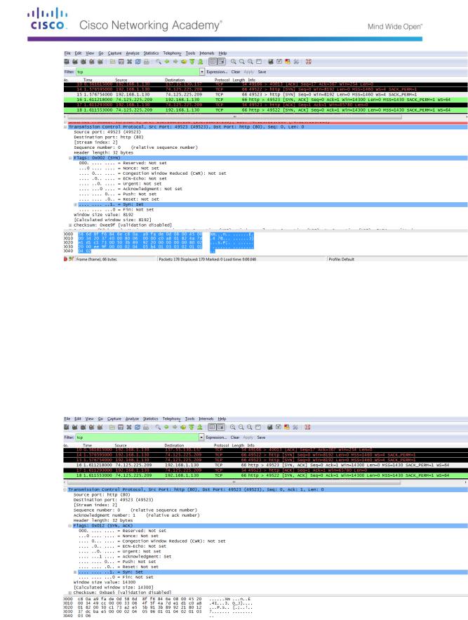
What is the TCP source port number? __________________________
How would you classify the source port? ________________________
What is the TCP destination port number? _______________________
How would you classify the destination port? _____________________
Which flag (or flags) is set? ________________________
What is the relative sequence number set to? ____________________
To select the next frame in the three-way handshake, select Go on the Wireshark menu and select Next Packet In Conversation. In this example, this is frame 16. This is the Google web server reply to the initial request to start a session.
What are the values of the source and destination ports?
______________________________________
Which flags are set?
___________________________________________________________________
© 2013 Cisco and/or its affiliates. All rights reserved. This document is Cisco Public. Page 140 of 257