

CCNA_R&S-Student_Lab_Manual
.pdfWhat are the three sections displayed in the output?
_____________________________________________________________________________
__________
Step 3: Examine the Interface List.
The first section, Interface List, displays the Media Access Control (MAC) addresses and assigned interface number of every network-capable interface on the host.
The first column is the interface number. The second column is the list of MAC addresses associated with the network-capable interfaces on the hosts. These interfaces can include Ethernet, Wi-Fi and Bluetooth adapters. The third column shows the manufacturer and a description of the interface.
© 2013 Cisco and/or its affiliates. All rights reserved. This document is Cisco Public. Page 111 of 257
In this example, the first line displays the wireless interface that is connected to the local network.
Note: If you have a PC with an Ethernet interface and a Wireless adapter enabled, both interfaces would be listed in the Interface List.
What is the MAC address of the interface connected to your local network? How does the MAC address compare to the recorded MAC address in Step 1?
_____________________________________________________________________________
__________
_____________________________________________________________________________
__________
The second line is loopback interface. The loopback interface is automatically assigned an IP address of 127.0.0.1 when the Transmission Control Protocol/Internet Protocol (TCP/IP) is running on a host.
The last four lines represent transition technology that allows communication in a mixed environment and includes IPv4 and IPv6.
Part 22: Examine IPv4 Host Routing Table Entries
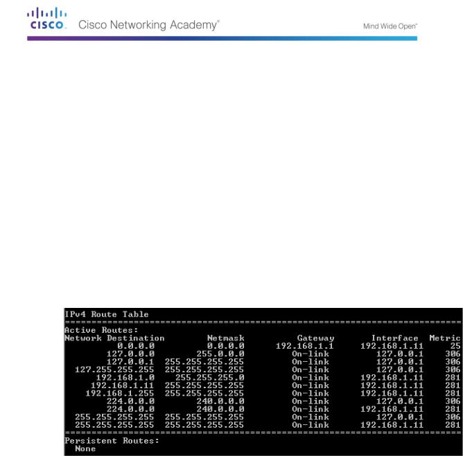
In Part 2, you will examine the IPv4 host routing table. This table is in the second section as a result of the netstat –r output. It lists all the known IPv4 routes, including direct connections, local network, and local default routes.
The output is divided in five columns: Network Destination, Netmask, Gateway, Interface, and Metric.
The Network Destination column lists the reachable network. The Network Destination is used with Netmask to match the destination IP address.
The Netmask lists the subnet mask that the host uses to determine the network and host portions of the IP address.
The Gateway column lists the address that the host uses to send the packets to a remote network destination. If a destination is directly connected, the gateway is listed as On-link in the output.
The Interface column lists the IP address that is configured on the local network adaptor. This is used to forward a packet on the network.
The Metric column lists the cost of using a route. It is used to calculate the best route to a destination. A preferred route has a lower metric number than other routes listed.
The output displays five different types of active routes:
© 2013 Cisco and/or its affiliates. All rights reserved. This document is Cisco Public. Page 112 of 257

The local default route 0.0.0.0 is used when the packet does not match other specified addresses in the routing table. The packet will be sent to the gateway from the PC for further processing. In this example, the packet will be sent to 192.168.1.1 from 192.168.1.11.
The loopback addresses, 127.0.0.0 – 127.255.255.255, are related to direct connection and provide services to the local host.
The addresses for the subnet, 192.168.1.0 – 192.168.1.255, are all related to the host and the local network. If the final destination of the packet is in the local network, the packet will exit 192.168.1.11 interface.
-The local route address 192.168.1.0 represents all devices on the 192.168.1.0/24 network.
-The address of the local host is 192.168.1.11.
-The network broadcast address 192.168.1.255 is used to send messages to all the hosts on the local network.
The special multicast class D addresses 224.0.0.0 are reserved for use through either the loopback interface (127.0.0.1) or the host (192.168.1.11).
The local broadcast address 255.255.255.255 can be used through either the loopback interface (127.0.0.1) or host (192.168.1.11).
Based on the contents of the IPv4 routing table, if the PC wanted to send a packet to 192.168.1.15, what would it do and where would it send the packet?
_____________________________________________________________________________
__________
_____________________________________________________________________________
__________
_____________________________________________________________________________
__________
_____________________________________________________________________________
__________
_____________________________________________________________________________
__________
If the PC wanted to send a packet to a remote host located at 172.16.20.23, what would it do and where would it send the packet?
_____________________________________________________________________________
__________
_____________________________________________________________________________
__________
_____________________________________________________________________________
__________
_____________________________________________________________________________
__________
_____________________________________________________________________________
__________
_____________________________________________________________________________
__________
_____________________________________________________________________________
__________
_____________________________________________________________________________
__________
© 2013 Cisco and/or its affiliates. All rights reserved. This document is Cisco Public. Page 113 of 257
Part 23: Examine IPv6 Host Routing Table Entries
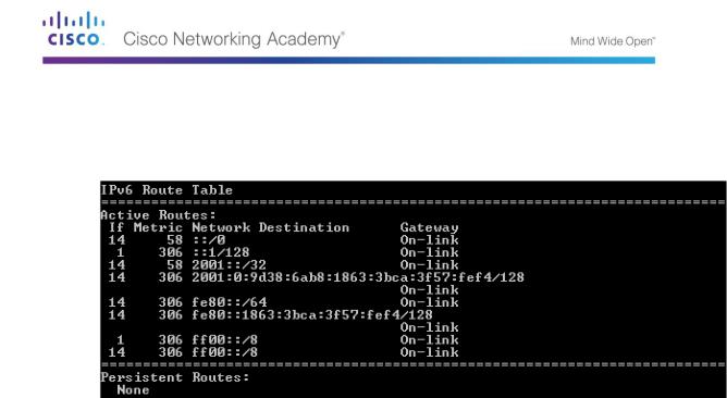
In Part 3, you will examine the IPv6 routing table. This table is in the third section displayed in the netstat –r output. It lists all the known IPv6 routes including direct connections, local network and local default routes.
The output of the IPv6 Route Table differs in column headings and format because the IPv6 addresses are 128 bits versus only 32 bits for IPv4 addresses. The IPv6 Route Table section displays four columns:
The If column lists the interface numbers of the IPv6-enabled network interfaces from the Interface List section of the netstat –r command.
The Metric column lists the cost of each route to a destination. The lower cost is the preferred route, and the metric is used to select between multiple routes with the same prefix.
The Network Destination column lists the address prefix for the route.
The Gateway lists the next-hop IPv6 address to reach the destination. On-link is listed as the next-hop address if it is directly connected to the host.
In this example, the figure displays the IPv6 Route Table section generated by the netstat –r command to reveal the following network destinations:
::/0: This is the IPv6 equivalent of the local default route. The Gateway column provides the link-local address of the default router.
::1/128: This is equivalent to the IPv4 loopback address and provides services to the local host.
2001::/32: This is the global unicast network prefix.
2001:0:9d38:6ab8:1863:3bca:3f57:fef4/128: This is the global unicast IPv6 address of the local computer.
fe80::/64: This is the local link network route address and represents all computers on the local-link IPv6 network.
fe80::1863:3bca:3f57:fef4/128: This is the link-local IPv6 address of the local computer.
ff00::/8: These are special reserved multicast class D addresses equivalent to the IPv4 224.x.x.x addresses.
The host routing table for IPv6 has similar information as the IPv4 routing table. What is the local default route for IPv4 and what is it for IPv6?
_____________________________________________________________________________
__________
What is the loopback address and subnet mask for IPv4? What is the loopback IP address for IPv6?
© 2013 Cisco and/or its affiliates. All rights reserved. This document is Cisco Public. Page 114 of 257

_____________________________________________________________________________
__________
How many IPv6 addresses have been assigned to this PC?
_____________________________________________________________________________
__________
How many broadcast addresses does the IPv6 routing table contain?
_____________________________________________________________________________
__________
Reflection
1.How is the number of bits for the network indicated for IPv4. How is it done for IPv6?
_____________________________________________________________________________
_________
2.Why is there both IPv4 and IPv6 information in the host routing tables?
_____________________________________________________________________________
__________
_____________________________________________________________________________
__________
© 2013 Cisco and/or its affiliates. All rights reserved. This document is Cisco Public. Page 115 of 257
Lab 14 - Exploring Router Physical Characteristics
Topology
Objectives
Part 1: Examine Router External Characteristics
Identify the various parts of a Cisco router, including:
-Management ports
-LAN interfaces
-WAN interfaces
-Module expansion slots
-Compact Flash memory expansion slots
-USB ports
Examine the router activity and status lights.
Part 2: Examine Router Internal Characteristics Using Show Commands
Establish a console connection to the router using Tera Term.
Identify router internal characteristics using the show version command.
Identify router interface characteristics using show interface commands.
Background / Scenario
In this lab, you will examine the outside of the router to become familiar with its characteristics and components, such as its power switch, management ports, LAN and WAN interfaces, indicator lights, network expansion slots, memory expansion slots, and USB ports.
You will also identify the internal components and characteristics of the IOS by consoling into the router and issuing various commands, such as show version and show interfaces, from the CLI.
Note: The routers used with CCNA hands-on labs are Cisco 1941 Integrated Services Routers (ISRs) with Cisco IOS Release 15.2(4)M3 (universalk9 image). Other routers and Cisco IOS versions can be used. Depending on the model and Cisco IOS version, the commands available and output produced might vary from what is shown in the labs.
Note: Make sure that the routers have been erased and have no startup configurations. If you are unsure, contact your instructor.
Required Resources
1 Router (Cisco 1941 with Cisco IOS Release 15.2(4)M3 universal image or comparable)
1 PC (Windows 7, Vista, or XP with terminal emulation program, such as Tera Term)
Console cables to configure the Cisco IOS devices via the console ports
©2013 Cisco and/or its affiliates. All rights reserved. This document is Cisco Public.
Page 116 of 257
Part 24: Examine Router External Characteristics
Use the images below, as well as your own direct inspection of the backplane of a Cisco router, to answer the following questions. Feel free to draw arrows and circle the areas of the image that correctly identify the parts.
Note: The router depicted in the images below is a Cisco 1941 router, which may be different from the make and model of the routers in your particular academy. You can find device information and specifications for the Cisco 1941 series routers at the Cisco.com website. Additional information, including answers to many of the questions below can be found here:
http://www.cisco.com/en/US/prod/collateral/routers/ps10538/data_sheet_c78_556319.html
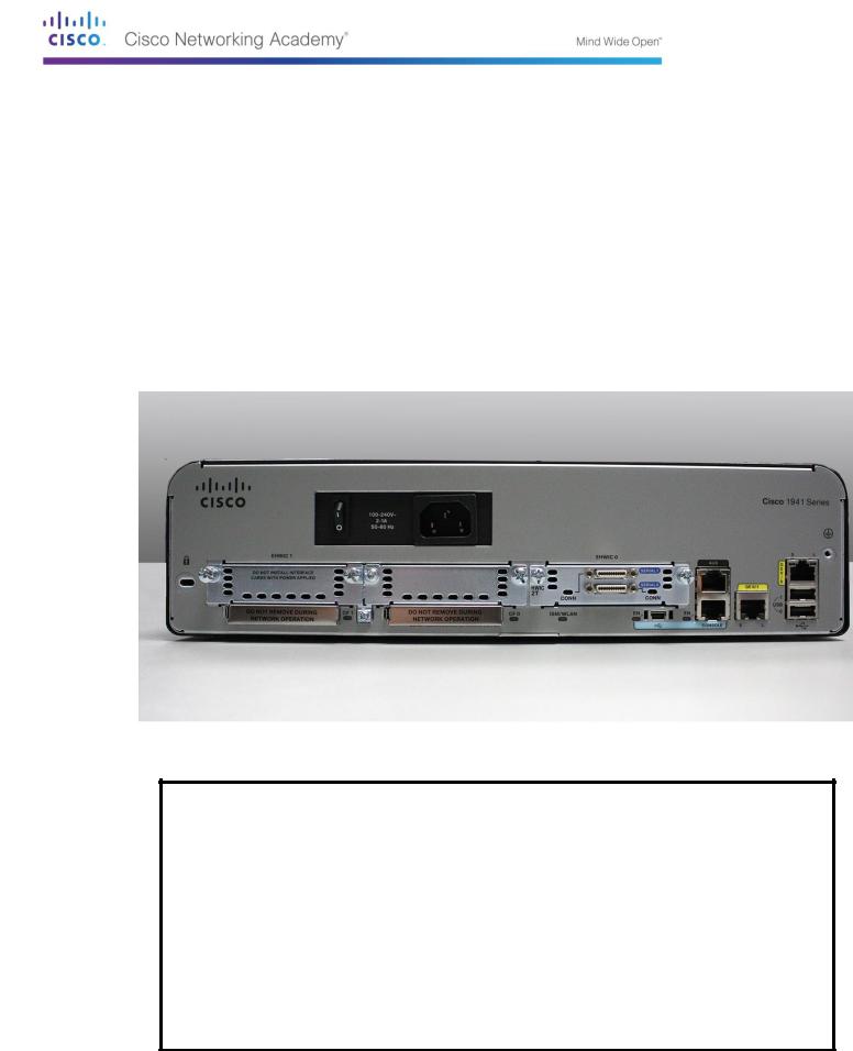
Step 1: Identify the various parts of a Cisco router.
The image shown in this step is of the backplane of a Cisco 1941 ISR. Use it to answer the questions in this step. In addition, if you are examining a different model router, a space has been provided here for you to draw the backplane and identify components and interfaces as specified in the questions that follow.
© 2013 Cisco and/or its affiliates. All rights reserved. This document is Cisco Public. Page 117 of 257

a.Circle and label the router’s power switch. Is the power switch on your router in the same area as the router depicted in the image?
__________________________________________________________________________
__________
b.Circle and label the management ports. What are the built-in management ports? Are the management ports the same on your router? If not, how are they different?
__________________________________________________________________________
__________
c.Circle and label the router’s LAN interfaces. How many LAN interfaces does the router in the image have and what is the interface technology type? Are the LAN interfaces the same on your router? If not, how are they different?
__________________________________________________________________________
__________
d.Circle and label the router’s WAN interfaces. How many WAN interfaces does the router in the image have and what is the interface technology type? Are the WAN interfaces the same on your router? If not, how are they different?
__________________________________________________________________________
__________
e.The Cisco 1941 ISR is a modular platform and comes with module expansion slots for varied network connectivity requirements. Circle and label the module slots. How many module slots are there? How many are used? What type of module expansion slots are they? Are the module slots the same on your router? If not, how are they different?
__________________________________________________________________________
__________
f.The Cisco 1941 router comes with CompactFlash memory slots for high speed storage. Circle and label the CompactFlash memory slots. How many memory slots are there? How many are used? How much memory can they hold? Are the memory slots the same on your router? If not, how are they different?
__________________________________________________________________________
__________
g.The Cisco 1941 router comes with USB 2.0 ports. The built-in USB ports support eToken devices and USB flash memory. The USB eToken device feature provides device authentication and secure configuration of Cisco routers. The USB flash feature provides optional secondary storage capability and an additional boot device. Circle and label the USB ports. How many USB ports are there? Are there USB ports on your router?
__________________________________________________________________________
__________
h.The Cisco 1941 router also comes with a mini-B USB console port. Circle and label the mini-B USB console port.
__________________________________________________________________________
__________
Step 2: Examine the router activity and status lights.
The following images highlight the activity and status lights of the front panel and backplane of a powered up and connected Cisco 1941 ISR.
Note: Some of the indicator lights are obscured from view in the image of the backplane of the Cisco 1941 router below.
© 2013 Cisco and/or its affiliates. All rights reserved. This document is Cisco Public. Page 118 of 257
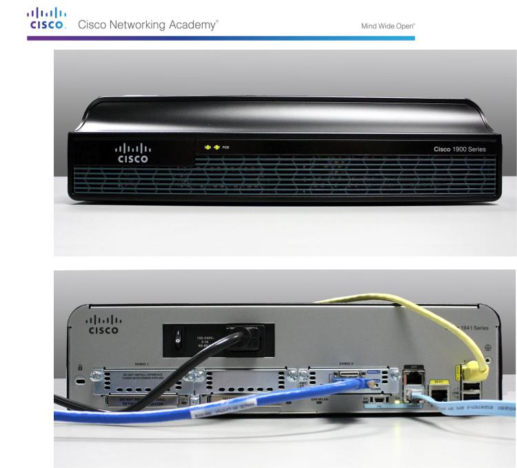
a.In the top image above, examine the indicator lights on the front panel of the router? The lights are labeled SYS, ACT, and POE. What do the labels refer to? What do the lights in the image indicate about the status of the router? These labels would be readable if they were not lit.
__________________________________________________________________________
__________
__________________________________________________________________________
__________
__________________________________________________________________________
__________
b.In the backplane image above, examine the indicator lights on the router. There are three visible activity lights, one for each of the connected interfaces and management ports. Examine the interface lights on your router. How are the lights labeled, and what is their meaning?
__________________________________________________________________________
__________
©2013 Cisco and/or its affiliates. All rights reserved. This document is Cisco Public.
Page 119 of 257

__________________________________________________________________________
__________
c.Aside from the management ports and network interfaces, what other indicator lights are on the backplane of the router and what might their purpose be?
__________________________________________________________________________
__________
__________________________________________________________________________
__________
__________________________________________________________________________
__________
Part 25: Examine Router Internal Characteristics Using Show
Commands
Step 1: Establish a console connection to the router and use the show version command.
a.Using Tera Term, console into the router and enter privileged EXEC mode using the enable command:
Router> enable Router#
b.Display information about the router by using the show version command. Use the Spacebar on the keyboard to page through the output.
Router# show version
Cisco IOS Software, C1900 Software (C1900-UNIVERSALK9-M), Version 15.2(4)M3, RELEASE SOFTWARE (fc1)
Technical Support: http://www.cisco.com/techsupport Copyright (c) 1986-2011 by Cisco Systems, Inc. Compiled Thu 26-Jul-12 19:34 by prod_rel_team
ROM: System Bootstrap, Version 15.0(1r)M15, RELEASE SOFTWARE (fc1)
Router uptime is 1 day, 14 hours, 46 minutes System returned to ROM by power-on
System restarted at 07:26:55 UTC Mon Dec 3 2012
System image file is "flash0:c1900-universalk9-mz.SPA.152-4.M3.bin" Last reload type: Normal Reload
Last reload reason: power-on
<output omitted>
If you require further assistance please contact us by sending email to export@cisco.com.
Cisco CISCO1941/K9 (revision 1.0) with 487424K/36864K bytes of memory. Processor board ID FGL16082318
2Gigabit Ethernet interfaces
2Serial(sync/async) interfaces
1terminal line
1Virtual Private Network (VPN) Module
©2013 Cisco and/or its affiliates. All rights reserved. This document is Cisco Public.
Page 120 of 257