

CCNA_R&S-Student_Lab_Manual
.pdfUsage: tracert [-d] [-h maximum_hops] [-j host-list] [-w timeout] [-R] [-S srcaddr] [-4] [-6] target_name
Options: |
|
-d |
Do not resolve addresses to hostnames. |
-h maximum_hops |
Maximum number of hops to search for target. |
-j host-list |
Loose source route along host-list (IPv4-only). |
-w timeout |
Wait timeout milliseconds for each reply. |
-R |
Trace round-trip path (IPv6-only). |
-S srcaddr |
Source address to use (IPv6-only). |
-4 |
Force using IPv4. |
-6 |
Force using IPv6. |
Use the -d option. Notice that the IP address of 192.168.3.3 is not resolved as PC-C.
C:\Users\User1> tracert –d 192.168.3.3
Tracing route to 192.168.3.3 over a maximum of 30 hops:
1 |
<1 ms |
<1 ms |
<1 ms |
192.168.1.1 |
||||
2 |
24 |
ms |
24 |
ms |
24 |
ms |
10.1.1.2 |
|
3 |
48 |
ms |
48 |
ms |
48 |
ms |
10.2.2.1 |
|
|
|
|
|
|
|
|
|
|
4 |
59 |
ms |
59 |
ms |
59 |
ms |
|
192.168.3.3 |
|
|
|
|
|
|
|
|
|
Trace complete.
Step 5: Use the traceroute command from the LOCAL router to PC-C.
At the command prompt, type traceroute 192.168.3.3 or The hostnames are resolved because a local IP host router.
traceroute PC-C on the LOCAL router. table was configured on the LOCAL
LOCAL# traceroute 192.168.3.3
Type escape sequence to abort.
Tracing the route to PC-C (192.168.3.3) VRF info: (vrf in name/id, vrf out name/id)
1 ISP (10.1.1.2) 16 msec 16 msec 16 msec
2 REMOTE (10.2.2.1) 28 msec 32 msec 28 msec 3 PC-C (192.168.3.3) 32 msec 28 msec 32 msec
LOCAL# traceroute PC-C
Type escape sequence to abort.
Tracing the route to PC-C (192.168.3.3) VRF info: (vrf in name/id, vrf out name/id)
1 ISP (10.1.1.2) 16 msec 16 msec 16 msec
2 REMOTE (10.2.2.1) 28 msec 32 msec 28 msec 3 PC-C (192.168.3.3) 32 msec 32 msec 28 msec
Step 6: Use the traceroute command from the S1 switch to PC-C.
On the S1 switch, type traceroute 192.168.3.3. The hostnames are not displayed in the traceroute results because a local IP host table was not configured on this switch.
S1# traceroute 192.168.3.3
Type escape sequence to abort. Tracing the route to 192.168.3.3
VRF info: (vrf in name/id, vrf out name/id)
© 2013 Cisco and/or its affiliates. All rights reserved. This document is Cisco Public. Page 181 of 257

1 192.168.1.1 1007 msec 0 msec 0 msec
2 10.1.1.2 17 msec 17 msec 16 msec
3 10.2.2.1 34 msec 33 msec 26 msec
4 192.168.3.3 33 msec 34 msec 33 msec
The traceroute command has additional options. You can use the ? or just press Enter after typing traceroute at the prompt to explore these options.
The following link provides more information regarding the ping and traceroute commands for a Cisco device:
http://www.cisco.com/en/US/products/sw/iosswrel/ps1831/products_tech_note09186a00800a605 7.shtml
Part 26: Troubleshoot the Topology
Step 7: Erase the configurations on the REMOTE router.
Step 8: Reload the REMOTE router.
Step 9: Copy and paste the following configuration into the REMOTE router.
hostname REMOTE
no ip domain-lookup interface s0/0/1
ip address 10.2.2.1 255.255.255.252 no shutdown
interface g0/1
ip add 192.168.8.1 255.255.255.0 no shutdown
router eigrp 1
network 10.2.2.0 0.0.0.3 network 192.168.3.0 0.0.0.255 no auto-summary
end
Step 10: From the LOCAL network, use ping and tracert or traceroute commands to troubleshoot and correct the problem on the REMOTE network.
Use the ping and tracert commands from PC-A.
You can use the tracert command to determine end-to-end network connectivity. This tracert result indicates that PC-A can reach its default gateway of 192.168.1.1, but PC-A does not have network connectivity with PC-C.
C:\Users\User1> tracert 192.168.3.3
Tracing route to 192.168.3.3 over a maximum of 30 hops 1 <1 ms <1 ms <1 ms 192.168.1.1
2 192.168.1.1 reports: Destination host unreachable.
Trace complete.
One way to locate the network issue is to ping each hop in the network to PC-C. First determine if PC-A can reach the ISP router Serial 0/0/1 interface with an IP address of 10.2.2.2.
© 2013 Cisco and/or its affiliates. All rights reserved. This document is Cisco Public. Page 182 of 257

C:\Users\Utraser1> ping 10.2.2.2
Pinging 10.2.2.2 with 32 bytes of data:
Reply from 10.2.2.2: bytes=32 time=41ms TTL=254
Reply from 10.2.2.2: bytes=32 time=41ms TTL=254
Reply from 10.2.2.2: bytes=32 time=41ms TTL=254
Reply from 10.2.2.2: bytes=32 time=41ms TTL=254
Ping statistics for 10.2.2.2:
Packets: Sent = 4, Received = 4, Lost = 0 (0% loss),
Approximate round trip times in milli-seconds:
Minimum = 20ms, Maximum = 21ms, Average = 20ms
The ping was successful to the ISP router. The next hop in the network is the REMOTE router. Ping the REMOTE router Serial 0/0/1 interface with an IP address of 10.2.2.1.
C:\Users\User1> ping 10.2.2.1
Pinging 10.2.2.1 with 32 bytes of data:
Reply from 10.2.2.1: bytes=32 time=41ms TTL=253
Reply from 10.2.2.1: bytes=32 time=41ms TTL=253
Reply from 10.2.2.1: bytes=32 time=41ms TTL=253
Reply from 10.2.2.1: bytes=32 time=41ms TTL=253
Ping statistics for 10.2.2.1:
Packets: Sent = 4, Received = 4, Lost = 0 (0% loss),
Approximate round trip times in milli-seconds:
Minimum = 40ms, Maximum = 41ms, Average = 40ms
PC-A can reach the REMOTE router. Based on the successful ping results from PC-A to the REMOTE router, the network connectivity issue is with 192.168.3.0/24 network. Ping the default gateway to PC-C, which is the GigabitEthernet 0/1 interface of the REMOTE router.
C:\Users\User1> ping 192.168.3.1
Pinging 192.168.3.1 with 32 bytes of data:
Reply from 192.168.1.1: Destination host unreachable.
Reply from 192.168.1.1: Destination host unreachable.
Reply from 192.168.1.1: Destination host unreachable.
Reply from 192.168.1.1: Destination host unreachable.
Ping statistics for 192.168.3.1:
Packets: Sent = 4, Received = 4, Lost = 0 (0% loss),
PC-A cannot reach the GigabitEthernet 0/1 interface of the REMOTE router, as displayed by the results from the ping command.
The S3 switch can also be pinged from PC-A to verify the location of the networking connectivity issue by typing ping 192.168.3.11 at the command prompt. Because PC-A cannot reach GigabitEthernet 0/1 of the REMOTE router, PC-A probably cannot ping the S3 switch successfully, as indicated by the results below.
C:\Users\User1> ping 192.168.3.11
Pinging 192.168.3.11 with 32 bytes of data:
Reply from 192.168.1.1: Destination host unreachable.
Reply from 192.168.1.1: Destination host unreachable.
© 2013 Cisco and/or its affiliates. All rights reserved. This document is Cisco Public. Page 183 of 257
Reply from 192.168.1.1: Destination host unreachable.
Reply from 192.168.1.1: Destination host unreachable.
Ping statistics for 192.168.3.11:
Packets: Sent = 4, Received = 4, Lost = 0 (0% loss),
The tracert and ping results conclude that PC-A can reach the LOCAL, ISP, and REMOTE routers, but not PC-C or the S3 switch, nor the default gateway for PC-C.
Use the show commands to examine the running configurations for the the REMOTE router.
REMOTE# show ip interface brief
Interface |
IP-Address |
OK? Method |
Status |
||
Protocol |
|
|
|
|
|
Embedded-Service-Engine0/0 unassigned |
YES unset |
administratively |
|||
down down |
|
|
|
|
|
GigabitEthernet0/0 |
unassigned |
YES unset |
administratively |
||
down down |
|
|
|
|
|
|
|
|
|
|
|
GigabitEthernet0/1 |
192.168.8.1 |
YES manual |
up |
|
|
up |
|
|
|
|
|
Serial0/0/0 |
unassigned |
YES unset |
administratively |
||
down down |
|
|
|
|
|
Serial0/0/1 |
10.2.2.1 |
YES manual |
up |
||
up |
|
|
|
|
|
REMOTE# show run
<output omitted>
interface GigabitEthernet0/0 no ip address
shutdown duplex auto speed auto
!
interface GigabitEthernet0/1
ip address 192.168.8.1 255.255.255.0 duplex auto
speed auto
!
interface Serial0/0/0 no ip address shutdown
clock rate 2000000
!
interface Serial0/0/1
ip address 10.2.2.1 255.255.255.252 <output omitted>
The outputs of the show run and show ip interface brief commands indicate that the GigabitEthernet 0/1 interface is up/up, but was configured with an incorrect IP address.
Correct the IP address for GigabitEthernet 0/1.
REMOTE# configure terminal
Enter configuration commands, one per line. End with CNTL/Z.
REMOTE(config)# interface GigabitEthernet 0/1 REMOTE(config-if)# ip address 192.168.3.1 255.255.255.0
Verify that PC-A can ping and tracert to PC-C.
© 2013 Cisco and/or its affiliates. All rights reserved. This document is Cisco Public. Page 184 of 257

C:\Users\User1> ping 192.168.3.3
Pinging 192.168.3.3 with 32 bytes of data:
Reply from 192.168.3.3: bytes=32 time=44ms TTL=125
Reply from 192.168.3.3: bytes=32 time=41ms TTL=125
Reply from 192.168.3.3: bytes=32 time=40ms TTL=125
Reply from 192.168.3.3: bytes=32 time=41ms TTL=125
Ping statistics for 192.168.3.3:
Packets: Sent = 4, Received = 4, Lost = 0 (0% loss),
Approximate round trip times in milli-seconds:
Minimum = 40ms, Maximum = 44ms, Average = 41ms
C:\Users\User1> tracert 192.168.3.3
Tracing route to PC-C [192.168.3.3]
Over a maximum of 30 hops:
1 |
<1 ms |
<1 ms |
<1 ms |
192.168.1.1 |
|||
2 |
24 |
ms |
24 |
ms |
24 |
ms |
10.1.1.2 |
3 |
48 |
ms |
48 |
ms |
48 |
ms |
10.2.2.1 |
4 |
59 |
ms |
59 |
ms |
59 |
ms |
PC-C [192.168.3.3] |
Trace complete.
Note: This can also be accomplished using ping and traceroute commands from the CLI on the the LOCAL router and the S1 switch after verifying that there are no network connectivity issues on the 192.168.1.0/24 network.
Reflection
What could prevent ping or traceroute responses from reaching the originating device beside network connectivity issues?
_____________________________________________________________________________
__________
_____________________________________________________________________________
__________
If you ping a non-existent address on the remote network, such as 192.168.3.4, what is the message displayed by the ping command? What does this mean? If you ping a valid host address and receive this response, what should you check?
_____________________________________________________________________________
__________
_____________________________________________________________________________
__________
If you ping an address that does not exist in any network in your topology, such as 192.168.5.3, from a Windows-based PC, what is the message displayed by the ping command? What does this message indicate?
_____________________________________________________________________________
__________
_____________________________________________________________________________
__________
© 2013 Cisco and/or its affiliates. All rights reserved. This document is Cisco Public. Page 185 of 257
Router Interface Summary Table
|
|
|
Part 89: |
Router Interface Summary |
|
|
|
||
|
|
|
|
|
|
|
|
|
|
Part 90: |
Router |
Part 91: |
Ethernet |
Part 92: |
Ethernet |
Part 93: |
Serial |
Part 94: |
Serial |
Model |
|
Interface #1 |
Interface #2 |
Interface #1 |
Interface #2 |
||||
|
|
|
|
|
|
||||
1800 |
|
Fast Ethernet 0/0 (F0/0) |
Fast Ethernet 0/1 (F0/1) |
Serial 0/0/0 (S0/0/0) |
Serial 0/0/1 (S0/0/1) |
||||
|
|
|
|
|
|
||||
1900 |
|
Gigabit Ethernet 0/0 |
Gigabit Ethernet 0/1 |
Serial 0/0/0 (S0/0/0) |
Serial 0/0/1 (S0/0/1) |
||||
|
|
(G0/0) |
|
(G0/1) |
|
|
|
|
|
|
|
|
|
|
|
||||
2801 |
|
Fast Ethernet 0/0 (F0/0) |
Fast Ethernet 0/1 (F0/1) |
Serial 0/1/0 (S0/1/0) |
Serial 0/1/1 (S0/1/1) |
||||
|
|
|
|
|
|
||||
2811 |
|
Fast Ethernet 0/0 (F0/0) |
Fast Ethernet 0/1 (F0/1) |
Serial 0/0/0 (S0/0/0) |
Serial 0/0/1 (S0/0/1) |
||||
|
|
|
|
|
|
||||
2900 |
|
Gigabit Ethernet 0/0 |
Gigabit Ethernet 0/1 |
Serial 0/0/0 (S0/0/0) |
Serial 0/0/1 (S0/0/1) |
||||
|
|
(G0/0) |
|
(G0/1) |
|
|
|
|
|
|
|
|
|
|
|
|
|
|
|
Note: To find out how the router is configured, look at the interfaces to identify the type of router and how many interfaces the router has. There is no way to effectively list all the combinations of configurations for each router class. This table includes identifiers for the possible combinations of Ethernet and Serial interfaces in the device. The table does not include any other type of interface, even though a specific router may contain one. An example of this might be an ISDN BRI interface. The string in parenthesis is the legal abbreviation that can be used in Cisco IOS commands to represent the interface.
© 2013 Cisco and/or its affiliates. All rights reserved. This document is Cisco Public. Page 186 of 257
Lab 21 - Observing DNS Resolution
Objectives
Part 1: Observe the DNS Conversion of a URL to an IP Address
Part 2: Observe DNS Lookup Using the Nslookup Command on a Web Site Part 3: Observe DNS Lookup Using the Nslookup Command on Mail Servers
Background / Scenario
The Domain Name System (DNS) is invoked when you type a Uniform Resource Locator (URL), such as http://www.cisco.com, into a web browser. The first part of the URL describes which protocol is used. Common protocols are Hypertext Transfer Protocol (HTTP), Hypertext Transfer Protocol over Secure Socket Layer (HTTPS), and File Transfer Protocol (FTP).
DNS uses the second part of the URL, which in this example is www.cisco.com. DNS translates the domain name (www.cisco.com) to an IP address to allow the source host to reach the destination host. In this lab, you will observe DNS in action and use the nslookup (name server lookup) command to obtain additional DNS information. Work with a partner to complete this lab.
Required Resources
1 PC (Windows 7, Vista, or XP with Internet and command prompt access)
Part 95: Observe the DNS Conversion of a URL to an IP Address
a.Click the Windows Start button, type cmd into the search field, and press Enter. The command prompt window appears.
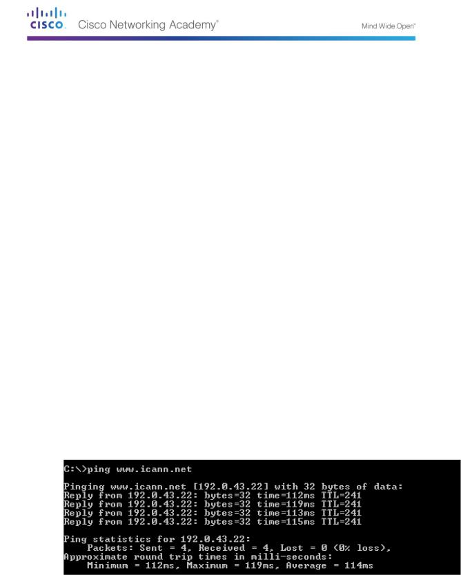
b.At the command prompt, ping the URL for the Internet Corporation for Assigned Names and Numbers (ICANN) at www.icann.net. ICANN coordinates the DNS, IP addresses, top-level domain name system management, and root server system management functions. The computer must translate www.icann.net into an IP address to know where to send the Internet Control Message Protocol (ICMP) packets.
c.The first line of the output displays www.icann.net converted to an IP address by DNS. You should be able to see the effect of DNS, even if your institution has a firewall that prevents pinging, or if the destination server has prevented you from pinging its web server.
Record the IP address of www.icann.net. __________________________________
© 2013 Cisco and/or its affiliates. All rights reserved. This document is Cisco Public. Page 187 of 257
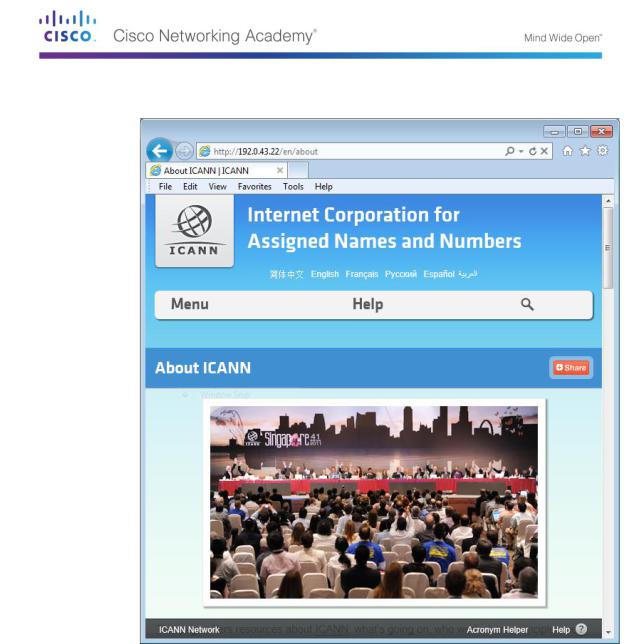
d.Type IP address from step c into a web browser, instead of the URL. Notice that the ICANN home web page is displayed.
Most humans find it easier to remember words, rather than numbers. If you tell someone to go to www.icann.net, they can probably remember that. If you told them to go to 192.0.43.22, they would have a difficult time remembering an IP address. Computers process in numbers. DNS is the process of translating words into numbers. There is a second translation that takes place. Humans think in Base 10 numbers. Computers process in Base 2 numbers. The Base 10 IP address 192.0.43.22 in Base 2 numbers is 11000000.00000000.00101011.00010110. What happens if you cut and paste these Base 2 numbers into a browser?
__________________________________________________________________________
__________
__________________________________________________________________________
__________
__________________________________________________________________________
__________
© 2013 Cisco and/or its affiliates. All rights reserved. This document is Cisco Public. Page 188 of 257
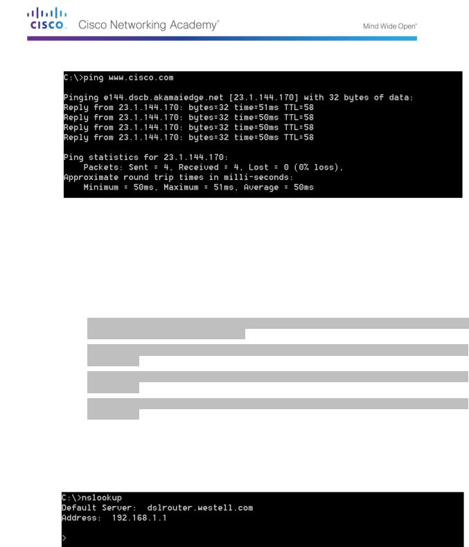
e. Now type ping www.cisco.com.
f.When you ping www.cisco.com, do you get the same IP address as the example, or a different IP address, and why?
__________________________________________________________________________
__________
__________________________________________________________________________
__________
__________________________________________________________________________
__________
g.Type the IP address that you obtained when you pinged www.cisco.com into a browser. Does the web site dlsplay? Why or why not?
__________________________________________________________________________
__________
__________________________________________________________________________
__________
__________________________________________________________________________
__________
Part 96: Observe DNS Lookup Using the Nslookup Command on a Web Site
a. At the command prompt, type the nslookup command.
What is the default DNS server used? _________________________________________
Notice how the command prompt changed to a greater than (>) symbol. This is the nslookup prompt. From this prompt, you can enter commands related to DNS.
At the prompt, type ? to see a list of all the available commands that you can use in nslookup mode.
© 2013 Cisco and/or its affiliates. All rights reserved. This document is Cisco Public. Page 189 of 257
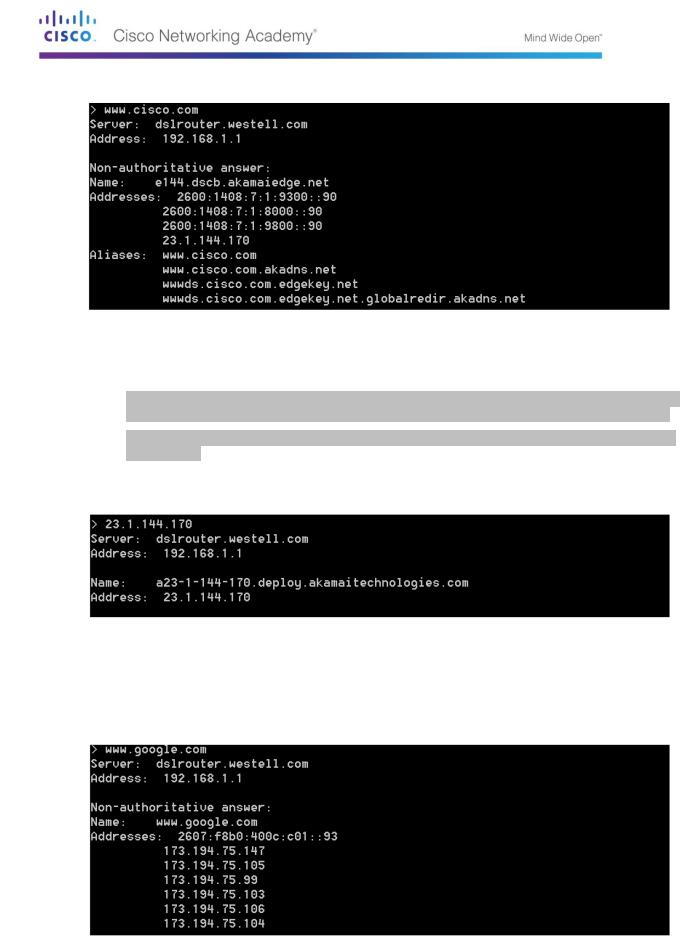
b. At the nslookup prompt, type www.cisco.com.
What is the translated IP address?
________________________________________________
Is it the same as the IP address shown with the ping command? _________________
Under addresses, in addition to the 23.1.144.170 IP address, there are the following numbers: 2600:1408:7:1:9300::90, 2600:1408:7:1:8000::90, 2600:1408:7:1:9800::90. What are these?
__________________________________________________________________________
__________
c.At the prompt, type the IP address of the Cisco web server that you just found. You can use nslookup to get the domain name of an IP address if you do not know the URL.
You can use the nslookup tool to translate domain names into IP addresses. You can also use it to translate IP addresses into domain names.
Using the nslookup tool, record the IP addresses associated with www.google.com.
__________________________________________________________________________
__________
© 2013 Cisco and/or its affiliates. All rights reserved. This document is Cisco Public. Page 190 of 257